Woodward EGCP-2 Installation Manual
Engine generator control package
Hide thumbs
Also See for EGCP-2:
- Installation and operation manual (234 pages) ,
- Operation manual (152 pages) ,
- Communications manual (64 pages)

Subscribe to Our Youtube Channel
Related Manuals for Woodward EGCP-2


Summary of Contents for Woodward EGCP-2
- Page 1 Installation (Set Builder) Manual EGCP-2 Engine Generator Control Package 8406-115, 150–300 Vac PT Input, 9–32 Vdc 8406-116, 50–150 Vac PT Input, 9–32 Vdc Manual 26076 (Revision F)
- Page 2 Revisions—Text changes are indicated by a black line alongside the text. Woodward Governor Company reserves the right to update any portion of this publication at any time. Information provided by Woodward Governor Company is believed to be correct and reliable. However, no responsibility is assumed by Woodward Governor Company unless otherwise expressly undertaken.
-
Page 3: Table Of Contents
HAPTER ANUAL PERATION 9. EGCP-2 C ..........112 HAPTER OMMUNICATIONS Overview ......................112 Modbus RTU Communications for the EGCP-2 Panel ........113 10. S ............. 121 HAPTER ERVICE PTIONS Product Service Options ..................121 Woodward Factory Servicing Options ..............122 ... - Page 4 Figure 3-3. Wiring Diagram for EGCP-2 ...............15 Figure 3-4. Dip Switch Location ................16 Figure 3-5. Three Wire Delta PT Connection for EGCP-2 ........17 Figure 3-6. Four Wire WYE PT Connection ............18 Figure 3-7. Utility / Local Bus PT Wiring for Delta and Wye Configuration ..19 Figure 3-8a.
- Page 5 Manual 26076 EGCP-2 Engine Generator Control Package Illustrations and Tables Figure 3-23. Generator Breaker and Contactor Close and Open Logic ....40 Figure 3-24. RS-422 Communications ..............45 Figure 3-25. RS-485 and RS-422 Termination Diagrams ........46 Figure 3-26. RS-485 Inter-Control Communications ..........47 Figure 4-1.
- Page 6 EGCP-2 Engine Generator Control Package Manual 26076 Illustrations and Tables Table 9-1. Examples of Modbus Control Mode Switching Logic ....... 114 Table 9-2. Modbus Addresses for the RTU Protocol ........117 Table 9-3. Common Modbus Error Numbers ............ 120 Table 9-4. Typical Modbus Communications Settings ........120 WARNING—EARTH GROUND...
-
Page 7: Regulatory Compliance
General Installation and Operation Notes and Warnings • The EGCP-2 is suitable for use in non-hazardous locations only. • Wiring must be in accordance with applicable electrical codes and in accordance with the authority having jurisdiction. -
Page 8: Electrostatic Discharge Awareness
PCB from the control cabinet, place it in the antistatic protective bag. CAUTION—ELECTROSTATIC DISCHARGE To prevent damage to electronic components caused by improper handling, read and observe the precautions in Woodward manual 82715, Guide for Handling and Protection of Electronic Controls, Printed Circuit Boards, and Modules. Woodward... -
Page 9: Chapter 1. General Information
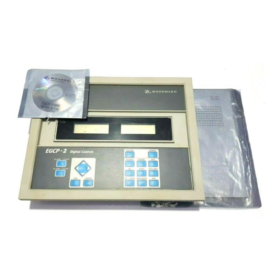
Manual 26076 EGCP-2 Engine Generator Control Package Chapter 1. General Information Introduction This manual describes the Woodward EGCP-2 Engine Generator Control Package, models 8406-115 and 8406-116 (9–32 Vdc maximum input voltage range). Control Electrical Ratings nominal supply voltage range 10–29 Vdc (12 or 14 volt systems) max. -
Page 10: Chapter 2. Control Overview
Woodward speed control to automate and protect diesel or gas engine based backup generator sets. Designed for small to medium size generator sets the EGCP-2 can be configured to operate stand-alone or utility paralleled sets. A network of EGCP-2 controls is capable of controlling up to eight un-manned generator sets for backup power, base-load, or peak shaving applications. - Page 11 • Externally adjustable VAR or PF control reference levels. Automatic Generator Sequencing • Automatically starts additional EGCP-2 equipped generators when load exceeds a user specified percentage of the rated load of the operating machines. • Provides controlled unloads for engines when the load is low enough that the remaining engines will not exceed a user specified percentage of the rated load.
-
Page 12: Figure 2-1. Egcp-2 Interface Connections
EGCP-2 Engine Generator Control Package Manual 26076 Figure 2-1. EGCP-2 Interface Connections Woodward... -
Page 13: Operator Interface
9.0 Vdc, the LCD back light will shut off to conserve power. NOTE The EGCP-2 Operator Interface can only be used for unit configuration and monitoring. Unit start/stop, sync, or mode selection commands cannot be given through the EGCP-2’s front panel. - Page 14 EGCP-2 Engine Generator Control Package Manual 26076 There are a total of 19 keys on the keypad. Each of the keys has the following function(s): ALARM/EVENT LOG KEYS: ALARM / EVENT The ALARM/EVENT key is used to access the Event log.
- Page 15 Manual 26076 EGCP-2 Engine Generator Control Package NAVIGATION and ADJUSTMENT KEYS: SCROLL The SCROLL KEY is used to move the cursor up, down , left and right. It also is used to increment and decrement values while in the configuration menus.
- Page 16 EGCP-2 Engine Generator Control Package Manual 26076 CONFIG The CONFIG KEY, when pressed, will put the right hand LCD into the configuration mode. Configuration menu items will be displayed in the right hand screen. Status information will continue to be displayed in the left hand screen.
-
Page 17: Hardware
The EGCP-2 is an integrated control package. All control hardware is contained in one compact enclosure. Figure 2-3 is a physical outline drawing with dimensions of the EGCP-2 for reference during the construction of mounting panels, etc. To mount the EGCP-2 panel use type M5 x 12mm thread forming screws (Woodward part number 1029-529). -
Page 18: Environmental Specification
EGCP-2. See Appendix A for mating connector information. • 5417-551—Communication Cable for RS422. This cable will connect your PC to the EGCP-2 RS422 port. This is a point-to-point connection. It can be used with EGCP-2 software tools. •... -
Page 19: Figure 2-3. Physical Outline With Dimensions Of Egcp-2
Manual 26076 EGCP-2 Engine Generator Control Package Figure 2-3. Physical Outline with Dimensions of EGCP-2 Woodward... -
Page 20: Chapter 3. Electrical Installation And Specifications
Wiring Fixed Terminal Figure 3-1. CageClamp Termination Blocks (example photos) Most of the EGCP-2 control’s terminal blocks are designed to be removed by hand. After EGCP-2 input power is disconnected, the terminal blocks can be removed one at a time by pulling them straight out. Care should be taken not to pull the plug out at an angle as this will fracture the end terminal. -
Page 21: Figure 3-2. Recommended Single Point Grounding Scheme
EGCP-2 Engine Generator Control Package NOTE Do not tin (add solder to) the wires that terminate at the EGCP-2 terminal blocks. The spring-loaded CageClamp terminal blocks are designed to flatten stranded wire, and if those strands are tinned together, the connection loses surface area and is degraded. - Page 22 All other shield terminations except at the EGCP-2 should be ac coupled to earth through a capacitor. A 1000 pF, 500 V capacitor is sufficient. The intent is to provide a low impedance path to earth for the shield at frequencies of 150 kHz and up.
-
Page 23: Figure 3-3. Wiring Diagram For Egcp-2
Manual 26076 EGCP-2 Engine Generator Control Package Figure 3-3. Wiring Diagram for EGCP-2 Woodward... -
Page 24: Input Power
CLOSED position. Input Power The EGCP-2 accepts any input power source that supplies a voltage within the 9-32 Vdc voltage range. It is expected that the installation of this equipment will include overcurrent protection between the power source and the EGCP-2. This... -
Page 25: Potential Transformer (Pt) Inputs
Potential Transformer (PT) Inputs Potential Transformers (PTs) are utilized with the EGCP-2 control to allow high level circuit voltages to be stepped down to a safe level for the EGCP-2 input circuitry. The EGCP-2 control senses generator output voltage through three... -
Page 26: Figure 3-6. Four Wire Wye Pt Connection
When the Mains PT Disconnect changes state, the EGCP-2 has to measure less than 40 Vac on the Mains/Bus PT input (terminals 40 and 41). If the EGCP-2 measures greater than 40 Vac after the Mains PT Disconnect command was given, the EGCP-2 senses this as a fault and will not synchronize. -
Page 27: Figure 3-7. Utility / Local Bus Pt Wiring For Delta And Wye Configuration
3. K1 and K2 relays should be connected as normally open contacts NOTE Because the same EGCP-2 input is used to sense both the utility and local bus voltages, the two PT signals must be identical in configuration (WYE or Delta), phase (A-B or A-N), and amplitude for correct input readings. -
Page 28: Figure 3-8A. Utility/Local Bus Single Pt Wiring For Delta And Wye Configuration (Two Relay)
EGCP-2 Engine Generator Control Package Manual 26076 EGCP-2 Prime Power or NOTES: *K1 SHOWN ENERGIZED Single - *K2 SHOWN DE-ENERGIZED Mains PT (+V) Engine LOMs - *K1 & K2 RELAYS ARE NOT Disconnect SUPPLIED BY WOODWARD (Normally Applications - *K1 & K2 RELAYS SHOULD... -
Page 29: Figure 3-9A. Pt Wiring Relationships For Generator, Bus, And Utility Inputs
Required PT Wiring Relationships The EGCP-2 control uses its programmed PT-Ratio setting to calculate and compare all PT input voltages. Thus, the EGCP-2 control requires the following generator, utility, and plant-bus PT relationships. Refer to Figures 3-9 and 3-10. EGCP-2... -
Page 30: Figure 3-9B. Pt Wiring Relationships For Generator, Bus, And Utility Inputs
Voltage Input: Delta PT Ratio : 2:1 Voltage Ref: 480 Vac, L-L Figure 3-9b. PT Wiring Relationships for Generator, Bus, and Utility Inputs Please Note: 1. This drawing shows EGCP-2 part number 8406-115. 2. Follow Utility/Local Bus PT wiring. Woodward... -
Page 31: Figure 3-10A. Pt Wiring Relationships For Generator, Bus, And Utility Inputs
Voltage Input: Wye VIS-148 01-03-16 PT Ratio : 4:1 Voltage Ref: 277 Vac, L-N Figure 3-10a. PT Wiring Relationships for Generator, Bus, and Utility Inputs Please Note: 1. This drawing shows EGCP-2 part number 8406-116. 2. Follow Utility/Local Bus PT wiring. Woodward... -
Page 32: Figure 3-10B. Pt Wiring Relationships For Generator, Bus, And Utility Inputs
Voltage Input: Wye VIS-148a PT Ratio : 1:1 01-03-29 Voltage Ref: 277 Vac, L-N Figure 3-10b. PT Wiring Relationships for Generator, Bus, and Utility Inputs Please Note: 1. This drawing shows EGCP-2 part number 8406-115. 2. Follow Utility/Local Bus PT wiring. Woodward... -
Page 33: Current Transformer (Ct) Inputs
Current Transformer (CT) Inputs Current Transformers (CTs) are utilized with the EGCP-2 control to allow high level circuit currents to be stepped down to a safe level for the EGCP-2 input circuitry. The EGCP-2 senses generator current via external current transformers. -
Page 34: Mpu (Speed) Input
The closer the MPU’s pole piece is to a gear’s teeth and the faster the gear turns the higher a passive MPU’s output amplitude will be. The EGCP-2 must sense an MPU voltage of 2 to 25 Vrms for proper operation. -
Page 35: Process Import/Export Input
The Process Import/Export input is used by the EGCP-2 control to sense the process level being controlled. This input can be DIP switch configured to accept either a 4–20 mA or 1–5 dc signal. -
Page 36: Coolant Temperature And Oil Pressure Inputs
Manual 26076 Coolant Temperature and Oil Pressure Inputs The EGCP-2 has one analog input dedicated to sense engine coolant temperature and one analog input dedicated to sense engine oil pressure. These inputs are optional and once connected-to can be configured to protect the engine by causing a system soft shutdown, hard shutdown, or alarm. -
Page 37: Figure 3-14B. Wiring Diagram For Temperature Inputs
Manual 26076 EGCP-2 Engine Generator Control Package +12 Vdc 537.5 SW2-1 Coolant Temperature SW 2-2 SW2-3 SW2-4 Sensor Input VIS-050b 01-01-31 Input 4-20mA 1-5 Volt 200 Ohm X - May be closed to insert 100 ohm shunt Sensor resistors required to make certain 0-200... -
Page 38: Speed Bias And Voltage Bias Outputs
Manual 26076 Speed Bias and Voltage Bias Outputs The EGCP-2’s Speed Bias output is a dedicated analog output, which is used to bias the prime mover’s speed control for unit synchronization and load control. The Speed Bias output is software configurable for outputs of ±3 Vdc, 0.5–4.5 Vdc, or 500 Hz PWM. -
Page 39: Discrete Inputs
40 milliseconds for the control to sense and register a change in state. All discrete inputs accept dry contacts only, with contact wetting voltage provided by the EGCP-2 control. The following is a list of the available EGCP-2 Discrete Inputs:... - Page 40 If the EGCP-2 control is in the VAR control mode (VAR control programmed, generator breaker closed, utility tie breaker closed), these contact inputs can be used to raise and lower unit VARs. If the EGCP-2 control is in the Power Factor control mode (Power Factor control programmed, generator breaker closed, utility tie breaker closed), these contact inputs can be used to raise and lower unit Power Factor.
-
Page 41: Relay Outputs
Figure 3-16. Wiring Diagram for Typical Discrete I/O Connections Relay Outputs Twelve (Form C type) Relay Outputs are used by the EGCP-2 control to interface with system devices. Before installation verify that the EGCP-2’s relay contacts meet the power requirements of the circuit with which it is being interfaced. -
Page 42: Figure 3-17. Example Of The Mains Breaker No Output Connected To Close The Mains (Utility) Breaker (Energize To Close)
6, and Normally Closed (NC), terminals 6 and 7, contacts to select from. The “Mains (utility) Breaker Close” relay output is utilized by the EGCP-2 to command the Mains (utility) Breaker to close. This output is configured for use with a BREAKER or a CONTACTOR in the Configuration menu under “CKT... -
Page 43: Figure 3-18. Example Using The Nc Output To Control The Mains (Utility) Contactor (Energize To Open)
ENERGIZE (continuously) to open the Mains Contactor. This is reverse logic from the Generator Contactor Close, discrete output # 2. External logic will be needed to verify the contactors state when installing or replacing EGCP-2 controls and for multiple control systems. -
Page 44: Figure 3-19. Example Of The Generator Breaker Close No Output Connected To Close The Generator Breaker (Energize To Close)
Contactor. The “Generator Breaker Trip”, discrete output #10, is NOT used in the Contactor mode. The EGCP-2 will DE-ENERGIZE (continuously) to open the Generators Contactor and ENERGIZE (continuously) to close the Generators Contactor. This is reverse logic from the Mains Contactor Close, discrete output # 1. - Page 45 The “Engine Preglow” relay output utilizes a set of normally open (NO) contacts on terminals 11 and 12. The “Engine Preglow” relay output is utilized by the EGCP-2 to turn on a diesel engine’s glow plugs, if so equipped. This relay will energize for a programmed length of time, based on the “Preglow Time”...
- Page 46 The “Local Bus PT Connect” relay utilizes a set of Normally Open (NO) contacts on terminals 21 and 22. The “Local Bus PT connect” relay output is utilized by the EGCP-2 to connect the Local Bus PT to the EGCP-2’s “Utility and Local Bus PT Input” on terminals 40 and 41.
-
Page 47: Figure 3-21. Example Using The No Contacts To Control The Mains Breaker Trip (Open) Coil (Energize To Open)
With the relay de-energized, this output has Normally Open (NO), terminals 28 and 29, and Normally Closed (NC), terminals 29 and 30, contacts to select from. The “Generator Breaker Trip (open)” relay output is utilized by the EGCP-2 to command the Generator Breaker to open. The relay output will DE-ENERGIZE to open the Generator Breaker. -
Page 48: Figure 3-22. Example Using The Nc Contacts To Control The Generator Breakers Open Coil (De-Energize To Open)
EGCP-2 Engine Generator Control Package Manual 26076 Generator EGCP-2 Breaker Trip Generator Breaker Trip (Open) Coil Discrete Output #10 VIS-154e 01-06-01 Figure 3-22. Example Using the NC Contacts to Control the Generator Breakers Open Coil (DE-ENERGIZE TO OPEN) EGCP-2 External Wiring... - Page 49 LED on the face of the EGCP-2 to flash. All alarm indicators will remain active until the alarm condition is acknowledged. No control actions occur as a result of an audible alarm condition.
-
Page 50: Ac Inputs
EGCP-2 Engine Generator Control Package Manual 26076 AC Inputs The EGCP-2 receives ac inputs from the generator, bus, mains and engine. They are as follows: Location Description Signal Burden Generator PT phase A + AC Voltage 200 kΩ Generator PT phase A –... -
Page 51: Discrete Inputs
Manual 26076 EGCP-2 Engine Generator Control Package Discrete Inputs Loc. Description Signal Input Auto Discrete Input (DI-1) + power supply (internal connection) Test Discrete Input (DI-2) + power supply (internal connection) Run/Ld Discrete Input (DI-3) + power supply (internal connection) -
Page 52: Communication Ports: Rs-485 & Rs-422 (1 Each)
2 control(s) RS-422 network. Modbus/ServLink Communications The laptop or desktop computer which will be used with the EGCP-2 RS-422 port will have a 9-pin serial port. This port is configured by the computer hardware to use a serial communications protocol called RS-232. The details of this protocol... -
Page 53: Figure 3-24. Rs-422 Communications
Manual 26076 EGCP-2 Engine Generator Control Package In a system with multiple (8 maximum) EGCP-2 controls, each control is interconnected to the others on the 422 network in a multidrop fashion. The computer is linked to the network at any control as if it were the next control on the network, as shown below. -
Page 54: Inter-Control Communications (Rs-485 Network)
1.0 mm² (16 AWG) wiring. Making this connection will force all communications transceivers to the same reference. As shown in Figure 3-25, the EGCP-2 uses Switch 4 (4-1, 4-2, and 4-3) to terminate the 485 network. Switches 4-1, 4-2, and 4-3 will be closed (pushed DOWN toward the PC board, see Figure 3-4) for proper 485 network terminations. -
Page 55: Alarms And Shutdowns
When an alarm setpoint is set for Warning, the alarm condition will cause the red LED on the face of the EGCP-2 to flash continuously until the alarm condition is acknowledged. No control actions occur as a result of a warning condition. - Page 56 When an alarm setpoint is set for Visual Alarm, the alarm condition will cause the visual alarm output relay to energize, and the red LED on the face of the EGCP-2 to Flash. Both indicators will remain active until the alarm condition is acknowledged.
- Page 57 Manual 26076 EGCP-2 Engine Generator Control Package These parameters for loss of mains detection are as follows: Load Surge Senses a step kW load change (% of Rated Load Setpoint per Second) on generator. LOM indication is immediate (no delay) for this condition.
-
Page 58: Chapter 4. Operational Description : Single N O Parallel
Operational Description: Single No Parallel The most basic mode of operation for the EGCP-2 is Single Unit No Parallel. In this configuration the generator will never parallel with the mains. All operations requiring the generator to be on load will take place with the mains breaker open. - Page 59 Manual 26076 EGCP-2 Engine Generator Control Package Transfer Switch Menu: Mains Under/Over Voltage Alarm: Loss of Mains Mains Under/Over Freq. Alarm: Loss of Mains NOTE Loss of Mains may be substituted with Loss of Mains w/alarms if alarm indications during a loss of mains condition are desired.
-
Page 60: Figure 4-1. Single No Parallel Application
Consult the Plant Wiring Diagram and Operational Description sections of the manual for more detail on the operating modes and wiring of the EGCP-2. NOTE These drawings show wiring for the breaker control options. See the plant wiring diagram in this manual for contactor wiring options. - Page 61 Manual 26076 EGCP-2 Engine Generator Control Package Switch Based Logic (Single—No Parallel) X OFF X STARTS ENGINE * X STARTS ENGINE * X OPENS TB / STARTS ENGINE / CLOSES GB / CONTROLS IN ISOCH OPENS TB / STARTS ENGINE / CLOSES GB / CONTROLS IN ISOCH OPENS GB / CLOSES TB / SHUTS DOWN ENGINE * = When generator breaker is closed manually, unit will operate in Droop mode.
-
Page 62: Figure 4-2A. Single No Parallel Overview Flow Diagram
EGCP-2 Engine Generator Control Package Manual 26076 Single Unit No Parallel Auto Input Test Input Run With Load Input Engine Loss of Mains Start Engine Enabled? Sequence Start Sequence Generator Engine Unit will not close gen Alarms/ breaker (must be in AUTO... -
Page 63: Figure 4-2B. Single No Parallel Overview Flow Diagram
Manual 26076 EGCP-2 Engine Generator Control Package Auto Input AND Run With Load Input Engine Start Sequence Loss of Mains Enabled? Gen Stable? OR Loss of Mains FLAG? Loss of Mains Detection Active Open Mains Breaker Sequence Loss of Mains for... -
Page 64: Figure 4-3. Single No Parallel Prime Power
EGCP-2 Engine Generator Control Package Manual 26076 LOAD No Mains Available (Prime Power Application) Number of Units = Single Mode of Load Transfer = Local No Parallel Mains PT Disconne t Application: Prime Power Connect Mode Selector Switch See Switch Logic Diagram for Details... -
Page 65: Chapter 5. Operational Description : Single Unit Parallel
2 will operate in either a base load (constant generator KW), or process control modes, depending on which switch inputs are received at the control. The EGCP-2 will also operate in a Power Factor or VAR control mode while in parallel with the Mains if the VAR/PF control setpoint in the Reactive Load Control tuning menu is set for either PF control or KVAR control. - Page 66 Upon sensing a loss of mains for the loss of mains action delay period, the EGCP-2 will open the mains breaker, start the generator set, wait for the gen stable time, and close the generator onto the dead bus, providing the load with power.
-
Page 67: Figure 5-1. Single Unit Parallel Application
Manual 26076 EGCP-2 Engine Generator Control Package Auto and Run with Load and Test Synchronizes and Ramps to Base Load. If “Load Control Mode” is set for Soft Transfer in configuration menu, unit will open mains breaker when base load reference is reached. - Page 68 EGCP-2 Engine Generator Control Package Manual 26076 Switch Based Logic (Single—Parallel) X OFF X STARTS ENGINE * X STARTS ENGINE * 1 READY TO START ENGINE UPON LOSS OF UTILITY POWER 1 STARTS ENGINE / SYNCHRONIZES TO UTILITY / CONTROLS IN BASELOAD...
-
Page 69: Figure 5-2A. Single Unit Parallel Overview Flow Diagram
Manual 26076 EGCP-2 Engine Generator Control Package Single Unit Mains Parallel Run With Load Test Input Auto Input Input Engine Engine Start Start Sequence Loss of Mains Sequence Enabled? Generator Unit will not close gen breaker (must be in AUTO... -
Page 70: Figure 5-2B. Single Unit Parallel Overview Flow Diagram
EGCP-2 Engine Generator Control Package Manual 26076 Single Parallel Unit Auto Input AND Run With Load Input Engine LOM Sequence Shown On Start Page #3 Sequence Loss of Mains Enabled? Gen Stable? Loss of Mains Detection Active Close Gen Breaker Sequence... -
Page 71: Figure 5-2C. Single Unit Parallel Overview Flow Diagram
Manual 26076 EGCP-2 Engine Generator Control Package Single Parallel Unit Run/Ld & Auto Loss of Mains From Page 2 FLAG? Open Mains Breaker Sequence Gen Breaker Closed? Gen Stable? Close Gen Breaker Sequence LOM Flag? Isoch Load Control Close Mains... -
Page 72: Chapter 6. Operating Mode: Multiple No Parallel
All operations of the generators on load in a multiple no parallel system are accomplished isolated from the mains. In a multiple unit system the EGCP-2 control operates in a Master/Slave type configuration. The master role is determined over the inter-control RS-485 network by the unit in Auto mode with the highest network priority (lowest numerical value). - Page 73 Manual 26076 EGCP-2 Engine Generator Control Package IMPORTANT When operating as standby units there must be at least one unit on the network and in Auto with the mains breaker aux input wired, and the Check Mains Breaker setpoint Enabled at any given time.
-
Page 74: Figure 6-1. Multiple Unit No Parallel Application
EGCP-2 Engine Generator Control Package Manual 26076 LOAD MAINS Number of Units = Multiple Mode of Load Transfer = Local No Parallel Mains PT Disconnect Application: Standby Power Connect Mode Selector Switch RS-485 LON See Swi t ch Logi c Di a gram for Detai l s... - Page 75 Manual 26076 EGCP-2 Engine Generator Control Package Switch Based Logic (Multiple—No Parallel, Master Control’s Action) STARTS MASTER ENGINE * STARTS MASTER ENGINE * READY TO START ALL ENGINES UPON LOSS OF UTILITY POWER OPENS TB / STARTS ALL ENGINES / CLOSES GB / CONTROLS IN ISOCH #...
-
Page 76: Figure 6-2A. Master Multiple Unit No Parallel Overview Flow Diagram
EGCP-2 Engine Generator Control Package Manual 26076 MASTER Multiple Unit No Parallel Test Input Run With Load Auto Input Page 1 Input Engine Engine Start Start Sequence Loss of Mains Sequence Enabled? Unit will not perform Unit will not perform... -
Page 77: Figure 6-2B. Master Multiple Unit No Parallel Overview Flow Diagram
Manual 26076 EGCP-2 Engine Generator Control Package MASTER Multiple Unit No Mains Parallel Auto Input AND Run With Load Page 2 Input Set System Engine RUN with Start LOAD Sequence FLAG Loss of Mains Enabled? Gen Stable? OR Loss of... -
Page 78: Figure 6-3A. Slave Multiple Unit No Parallel Overview Flow Diagram
EGCP-2 Engine Generator Control Package Manual 26076 SLAVE Multiple Unit No Parallel Page 1 Test Input Run With Load Auto Input Input Engine Engine Start Start Sequence Loss of Mains Sequence Enabled? Unit will not perform Unit will not perform... -
Page 79: Figure 6-3B. Slave Multiple Unit No Parallel Overview Flow Diagram
Manual 26076 EGCP-2 Engine Generator Control Package SLAVE Multiple Unit No Parallel Auto Input AND Page 2 Run With Load Input Engine Start Sequence Loss of Mains Enabled? Gen Stable? OR Loss of Mains FLAG? Loss of Mains Detection Active... -
Page 80: Figure 6-3C. Slave Multiple Unit No Parallel Overview Flow Diagram
EGCP-2 Engine Generator Control Package Manual 26076 SLAVE Multiple Unit No Parallel Auto Input AND Page 3 System Run With Load Flag Engine Start Sequence Loss of Mains Enabled? Gen Stable? OR Loss of Mains FLAG? Loss of Mains Detection Active... -
Page 81: Chapter 7. Operating Mode: Multiple Parallel
Operating Mode: Multiple Parallel The Multiple Parallel operating mode of the EGCP-2 is the most complex. In this mode, multiple generator sets have the capability to operate as: Standby Units upon loss of mains detection; Peak Shaving Units; Load Demand Reduction Units, and Soft Transfer Units. - Page 82 EGCP-2 Engine Generator Control Package Manual 26076 IMPORTANT There must be at least one unit on the network and in Auto with the mains breaker aux hard wired input, and configured for “Check Mains Breaker” setpoint “enabled” at any given time.
-
Page 83: Figure 7-1. Multiple Unit No Parallel Prime Power Application
Manual 26076 EGCP-2 Engine Generator Control Package LOAD No Mains Available (Prime Power Application) Number of Units = Multiple Mode of Load Transfer = Local No Parallel Mains PT Disconnect Application: Prime Power Connect Mode Selector Switch RS-485 LON See Swi t ch Logi c Di a gram for Detai l s... -
Page 84: Figure 7-2. Multiple Unit Parallel Standby Power Application
EGCP-2 Engine Generator Control Package Manual 26076 LOAD MAINS Number of Units = Multiple Watt Mode of Load Transfer = Xducer Local Mains Parallel Mains PT Disconnect Application: Standby Power and Connect Peak Shaving Set Process Input 4-20mA or 1-5VDC... -
Page 85: Figure 7-3. Multiple Unit Parallel Peak Shaving Application
Manual 26076 EGCP-2 Engine Generator Control Package LOAD MAINS Number of Units = Multiple Watt Mode of Load Transfer = Xducer Local Mains Parallel Mains PT Disconnect Application:Peak Shaving Set Connect Process Input 4-20mA or 1-5VDC Mode Selector Switch RS-485 LON... - Page 86 EGCP-2 Engine Generator Control Package Manual 26076 Switch Based Logic (Multiple—Parallel, Master Control’s Action) X OFF X STARTS ALL ENGINES * X STARTS ALL ENGINES * 1 READY TO START ALL ENGINES UPON LOSS OF UTILITY POWER 1 STARTS ALL ENGINES / ALL UNITS SYNC TO UTILITY / CONTROL IN BASELOAD...
-
Page 87: Figure 7-4A. Master Multiple Parallel Process Control Flow Diagram
Manual 26076 EGCP-2 Engine Generator Control Package MASTER Multiple Unit Utility Parallel Run With Load Test Input Auto Input Page 1 Input Engine Engine Start Start Sequence Loss of Mains Sequence Enabled? Generator Unit will not close gen breaker (must be in AUTO... -
Page 88: Figure 7-4B. Master Multiple Parallel Process Control Flow Diagram
EGCP-2 Engine Generator Control Package Manual 26076 MASTER Multiple Unit Utility Parallel Auto Input AND Page 2 Run With Load Input Set System Run with Load Flag and LOM Sequence Shown On Page #3 Engine Start Sequence Loss of Mains... -
Page 89: Figure 7-4C. Master Multiple Parallel Process Control Flow Diagram
Manual 26076 EGCP-2 Engine Generator Control Package MASTER Multiple Unit Utility Parallel Page 3 Loss of Mains From Pages 2,4,5 and 7 FLAG? Set System Run with Load Flag and Open Mains Breaker Sequence Gen Breaker Closed? Gen Stable? Close Gen Breaker... -
Page 90: Figure 7-4D. Master Multiple Parallel Process Control Flow Diagram
EGCP-2 Engine Generator Control Package Manual 26076 MASTER Multiple Unit Utility Parallel Page 4 Auto Input AND Run With Load Input AND Set System Run with Process Load Flag and LOM Sequence Shown On Engine Start Page #3 Sequence Loss of Mains... -
Page 91: Figure 7-4E. Master Multiple Parallel Process Control Flow Diagram
Manual 26076 EGCP-2 Engine Generator Control Package MASTER Multiple Unit Utility Parallel Page 5 Auto Input AND Run With Load Input AND Test Set System Run with LOM Sequence Shown On Load Flag and Engine Start Page #3 Sequence Loss of Mains... -
Page 92: Figure 7-4F. Master Multiple Parallel Process Control Flow Diagram
EGCP-2 Engine Generator Control Package Manual 26076 MASTER Multiple Unit Utility Parallel Page 6 Gen KW = Baseload From Page #5 Reference Setpoint? Mains Breaker Open Sequence Isoch Load Control with auto sequencing Run with Load and Test Run with Load Switch... -
Page 93: Figure 7-4G. Master Multiple Parallel Process Control Flow Diagram
Manual 26076 EGCP-2 Engine Generator Control Package MASTER Multiple Unit Utility Parallel Auto Input AND Run With Load Input Page 7 AND Process input AND Test Input Set System Run with Load LOM Sequence Shown On Flag and Engine Start... -
Page 94: Figure 7-4H. Master Multiple Parallel Process Control Flow Diagram
EGCP-2 Engine Generator Control Package Manual 26076 MASTER Multiple Unit Utility Parallel Process mA input = From Page 8 Page #7 Process Reference? Mains Breaker Open Sequence Isoch Load Control with auto sequencing Run with Load and Run with Load Switch... -
Page 95: Figure 7-5A. Slave Multiple Parallel Process Control Flow Diagram
Manual 26076 EGCP-2 Engine Generator Control Package SLAVE Multiple Unit Mains Parallel Page1 Run With Load Test Input Auto Input Input Engine Engine Start Start Sequence Loss of Mains Sequence Enabled? Generator Unit will not close gen breaker (must be in AUTO... -
Page 96: Figure 7-5B. Slave Multiple Parallel Process Control Flow Diagram
EGCP-2 Engine Generator Control Package Manual 26076 SLAVE Multiple Unit No Parallel Page 2 Auto Input AND Run With Load Input Engine Start Sequence Loss of Mains Enabled? Gen Stable? OR Loss of Mains FLAG? Loss of Mains Detection Active... -
Page 97: Figure 7-5C. Slave Multiple Parallel Process Control Flow Diagram
Manual 26076 EGCP-2 Engine Generator Control Package SLAVE Multiple Unit No Parallel Auto Input AND Page 3 System Run With Load Flag Engine Start Sequence Loss of Mains Enabled? Gen Stable? OR Loss of Mains FLAG? Loss of Mains Detection Active... -
Page 98: Figure 7-5D. Slave Multiple Parallel Process Control Flow Diagram
EGCP-2 Engine Generator Control Package Manual 26076 SLAVE Multiple Unit Mains Parallel Page1 Run With Load Test Input Auto Input Input Engine Engine Start Start Sequence Loss of Mains Sequence Enabled? Generator Unit will not close gen breaker (must be in AUTO... -
Page 99: Figure 7-5E. Slave Multiple Parallel Process Control Flow Diagram
Manual 26076 EGCP-2 Engine Generator Control Package SLAVE Multiple Unit Mains Parallel Auto Input AND Page 2 Run With Load Input Engine LOM Sequence Shown On Start Page #3 Sequence Loss of Mains Enabled? Gen Stable? Loss of Mains Detection Active... -
Page 100: Figure 7-5F. Slave Multiple Parallel Process Control Flow Diagram
EGCP-2 Engine Generator Control Package Manual 26076 SLAVE Multiple Unit Mains Parallel Page 3 Loss of Mains From Pages 2,4,5,7,9 FLAG? Open Mains Breaker Sequence Gen Breaker Closed? Gen Stable? Close Gen Breaker Sequence LOM Flag? Isoch Load Control Close Mains... -
Page 101: Figure 7-5G. Slave Multiple Parallel Process Control Flow Diagram
Manual 26076 EGCP-2 Engine Generator Control Package SLAVE Multiple Unit Mains Parallel Page 4 Auto Input AND Run With Load Input AND Process Engine LOM Sequence Shown On Start Page #3 Sequence Loss of Mains Enabled? Gen Stable? Loss of Mains... -
Page 102: Figure 7-5H. Slave Multiple Parallel Process Control Flow Diagram
EGCP-2 Engine Generator Control Package Manual 26076 SLAVE Multiple Unit Mains Parallel Page 5 Auto Input AND Run With Load Input AND Test Engine LOM Sequence Shown On Start Page #3 Sequence Loss of Mains Enabled? Gen Stable? Loss of Mains... -
Page 103: Figure 7-5J. Slave Multiple Parallel Process Control Flow Diagram
Manual 26076 EGCP-2 Engine Generator Control Package SLAVE Mul iple Unit Mains Parallel Page 6 Gen KW = Baseload From Page #5 Refernece Setpoint? Mains Breaker Open Sequence Isoch Load Control Run with Load and Test Run with Load Switch... -
Page 104: Figure 7-5K. Slave Multiple Parallel Process Control Flow Diagram
EGCP-2 Engine Generator Control Package Manual 26076 SLAVE Multiple Unit Mains Parallel Auto Input AND Page 7 Run With Load Input AND Process input AND Test Input Engine LOM Sequence Shown On Start Page #3 Sequence Loss of Mains Enabled? -
Page 105: Figure 7-5L. Slave Multiple Parallel Process Control Flow Diagram
Manual 26076 EGCP-2 Engine Generator Control Package SLAVE Multiple Unit Mains Parallel Page 8 Process mA input From Page #7 Process Reference? Mains Breaker Open Sequence Isoch Load Control Run with Load and Run with Load Switch Process Load Process and Test Switch... -
Page 106: Figure 7-5M. Slave Multiple Parallel Process Control Flow Diagram
EGCP-2 Engine Generator Control Package Manual 26076 SLAVE Multiple Unit Mains Parallel Auto Input AND Page 9 System Run With Load Flag Engine LOM Sequence Shown On Start Page #3 Sequence Loss of Mains Enabled? Gen Stable? Loss of Mains... -
Page 107: Figure 7-6. Generator Start Sequence
Manual 26076 EGCP-2 Engine Generator Control Package The following flow diagrams are specific sequences referred to in the preceding overview flow diagrams: Generator Start Sequence Test Input OR Run With Load Input OR (Auto & Run with load flag from Master) OR (Auto Input &... -
Page 108: Figure 7-7. Generator Stop Sequence
EGCP-2 Engine Generator Control Package Manual 26076 Generator Stop Sequence Test Input turned OFF AND Run With Load Input turned OFF AND (Auto & Run with load flag from Master) turned OFF AND (Auto Input & No LOM) Initialze Timers,... -
Page 109: Figure 7-8. Generator Breaker Close Sequence
Manual 26076 EGCP-2 Engine Generator Control Package Gen Breaker Close Sequence Sync Timeout Time Expired? Single No Mains Parallel Unit Close Gen Breaker FLAG = TRUE Force Sync Mode = OFF Initialize Timers, Counters Set Sync Reclose Alarm Close Attempts <... -
Page 110: Figure 7-9. Generator Breaker Close Sequence
EGCP-2 Engine Generator Control Package Manual 26076 Gen Breaker Close Sequence Sync Timeout Single Mains Parallel Unit Time Expired? Force Sync Close Gen Breaker FLAG = TRUE Mode = OFF Initialize Timers, Counters Set Sync Reclose Alarm Close Attempts <... -
Page 111: Figure 7-10. Generator Breaker Close Sequence
Manual 26076 EGCP-2 Engine Generator Control Package Gen Breaker Close Sequence Sync Timeout Time Expired? Multiple No Mains Parallel Unit Force Sync Mode = OFF Close Gen Breaker FLAG = TRUE Set Sync Initialize Timers, Reclose Alarm Counters Force Sync Close Attempts <... -
Page 112: Figure 7-11. Main Breaker Open Sequence
EGCP-2 Engine Generator Control Package Manual 26076 Mains Breaker Open Sequence Open Mains Breaker Flag Sync Timeout Time Expired? Initialize Timers Set Sync Reclose Alarm Note: Sync Timeout Alarm ONLY. Unit will continue to try opening Check Mains Mains Breaker until the Breaker = Mains CB Aux input goes open. -
Page 113: Figure 7-12. Mains Breaker Close Sequence
Manual 26076 EGCP-2 Engine Generator Control Package Parallel Mains Breaker Close Diagram Close Mains Breaker Flag Initialize Timers, Counters Check Mains Breaker = Enabled? Unit in Auto? Breaker Close Attempts > Close Attempts Logic? Setpoint? De-Energize Mains Energize Mains Breaker Close Phase <=... -
Page 114: Figure 7-13. Mains Breaker Reclose Sequence
EGCP-2 Engine Generator Control Package Manual 26076 Close Mains Parallel Mains Breaker Re-close Diagram Breaker Flag (occurs if mains opens due to external function) Initialize Timers, Counters Check Mains Breaker Setpoint =Enabled? Unit in Test? Unit in Run? Unit in Auto? Breaker Close Attempts >... -
Page 115: Figure 7-14. Mains Breaker Reclose Sequence
Manual 26076 EGCP-2 Engine Generator Control Package No Parallel Mains Breaker Re-Close Sequence Close Mains Breaker Flag Initialize Timers, Counters Unit in Test? Unit in Run? Unit in Auto? Close Attempts > Breaker Logic? Close Attempts Setpoint Energize Mains De-Energize Mains... -
Page 116: Figure 7-15. Speed Raise/Lower Switch Based Logic
EGCP-2 Engine Generator Control Package Manual 26076 Switch Based Logic (Speed Raise/Lower Contact Functionality) X X SPEED BIAS RAISE & LOWER * X DISABLED BASELOAD SETPOINT RAISE & LOWER * 1 1 PROCESS SETPOINT RAISE & LOWER * 1 = Breaker/Contact closed X = Breaker/Contact open or closed * = If both the Raise &... -
Page 117: Chapter 8. Manual Operation
Trip position. The user must wire around the Trip command in order to manually close the breaker. d. The EGCP-2 can be in a single or multiple unit / Mains Parallel e. Mains is Stable f. Mains Breaker is closed g. - Page 118 Trip position. The user must wire around the Trip command in order to manually close the breaker. d. The EGCP-2 can be in a single or multiple unit / Mains Parallel e. Mains is stable f. Mains Breaker is closed g.
- Page 119 Manual 26076 EGCP-2 Engine Generator Control Package 2. Shutdowns and Alarms a. The EGCP-2 does NOT control the Generator Breaker when in a Manual operating mode. This means that during a Soft or Hard shutdown sequence, the EGCP-2 cannot open the Generator Breaker (G52).
-
Page 120: Egcp-2 Communications
This interface allows access to readout and setpoint variables in the unit. ServLink software must be purchased from Woodward, or its distributors, and resident on the host computer in order to access the EGCP-2 data over the RS-422 communication port. For more information about Woodward products, which use ServLink, contact your local Woodward Distributor. -
Page 121: Modbus Rtu Communications For The Egcp-2 Panel
The Modbus address chosen for any particular EGCP-2 panel should be unique from any other devices on the Modbus network. NOTE The Network Address of the EGCP-2 panel is not linked to the Modbus ID in any way. Modbus Time-out is located in the Sequencing and Comms configuration menu. - Page 122 Modbus Information Addresses 00001–00016 Boolean Writes The Boolean write variables can be used for remote control of the EGCP-2 over Modbus. Fourteen variables are available to mimic the fourteen discrete input switches. The Gen CB Aux input and Mains CB Aux input are not included in the Modbus addresses.
- Page 123 Raise/Lower) are internally (EGCP-2 software) timed to open after a one second ON time. This means that if the EGCP-2 receives an ON command via Modbus for any of these four switches, the unit will turn the switch ON for one second, and then turn the input OFF.
- Page 124 0, -30, -60, -90, -120, -150, 180, 150, 120, 90, 60, 30, 0… Address 40001 Analogs Write The Analog Write variable can be used to change the priority of the EGCP-2 over Modbus. To change the priority the unit must be in the AUTO mode. When multiple units are in Auto the following rules apply to changing the priority.
- Page 125 Manual 26076 EGCP-2 Engine Generator Control Package When decreasing (incrementing value) a unit's priority, every active unit (in multiple unit configuration and auto mode) on the same network with a higher priority (lower value) than the unit, which is currently having its priority, changed, will increase (decrement value) priority when the priority change is committed.
- Page 126 EGCP-2 Engine Generator Control Package Manual 26076 Address Data Type/Scaling Description 10025 Input #8 Status (Gen CB Aux.) 10026 Input #9 Status (Mains CB Aux.) 10027 Input #10 Status (Process I/E) 10028 Input #11 Status (Fault #1) 10029 Input #12 Status (Fault #2)
- Page 127 Manual 26076 EGCP-2 Engine Generator Control Package Address Data Type/Scaling Description 30010 Total KW 30011 Total KVA 30012 AR X100 Generator Power Factor 30013 Phase A kVAR 30014 Phase B kVAR 30015 Phase C kVAR 30016 Total kVAR 30017 AR X10...
- Page 128 NOTE Communications settings will vary based on the Modbus system configuration. These settings are the recommended typical settings for a multiple unit EGCP-2 system connected to Modbus master. Woodward...
-
Page 129: Chapter 10. Service Options
A Recognized Turbine Retrofitter (RTR) is an independent company that does both steam and gas turbine control retrofits and upgrades globally, and can provide the full line of Woodward systems and components for the retrofits and overhauls, long term service contracts, emergency repairs, etc. -
Page 130: Woodward Factory Servicing Options
Flat Rate Remanufacture: Flat Rate Remanufacture is very similar to the Flat Rate Repair option with the exception that the unit will be returned to you in “like- new” condition and carry with it the full standard Woodward product warranty (Woodward Product and Service Warranty 5-01-1205). This option is applicable to mechanical products only. -
Page 131: Returning Equipment For Repair
CAUTION—ELECTROSTATIC DISCHARGE To prevent damage to electronic components caused by improper handling, read and observe the precautions in Woodward manual 82715, Guide for Handling and Protection of Electronic Controls, Printed Circuit Boards, and Modules. -
Page 132: Engineering Services
EGCP-2 Engine Generator Control Package Manual 26076 Engineering Services Woodward offers various Engineering Services for our products. For these services, you can contact us by telephone, by email, or through the Woodward website. • Technical Support • Product Training •... -
Page 133: Technical Assistance
Type of Fuel (gas, gaseous, steam, etc) Rating Application Control/Governor Information Please list all Woodward governors, actuators, and electronic controls in your system: Woodward Part Number and Revision Letter Control Description or Governor Type Serial Number Woodward Part Number and Revision Letter... -
Page 134: Appendix A. Connector Information
Appendix A. Connector Information Wago pluggable style terminal blocks are used on the EGCP-2 to connect the field wiring to the control. THESE CONNECTORS ARE NOT INCLUDED WITH THE EGCP-2. Woodward carries the EGCP-2 connector kit, which contains all of the terminal blocks used on the EGCP-2 as part number 8928-301. - Page 135 Manual 26076 EGCP-2 Engine Generator Control Package Recommended Wire Types: Size Insulation Type 0.3 mm²/ Multiple conductor, Discrete I/O 600V 22 AWG unshielded PT inputs Speed Bias, Voltage 0.3 mm²/ 300V Two conductor, shielded Bias, MPU, Oil and 22 AWG Water Sensors 1.0 mm²/...
-
Page 136: Appendix B. Speed Bias Connections
EGCP-2 Engine Generator Control Package Manual 26076 Appendix B. Speed Bias Connections EGCP-2 SPEED Speed Bias Output CONTROL EGCP-2 To EPG Speed Control Wiring and Configuration Settings VIS-125a Speed Bias Output Type = +/- 3VDC 00-06-20 EGCP-2 2301A Speed Bias Output... - Page 137 Manual 26076 EGCP-2 Engine Generator Control Package EGCP-2 FLO-TECH Speed Bias Output Speed Control EGCP-2 To FLO-TECH Speed Control Wiring and Configuration Settings VIS-127a 00-06-20 Speed Bias Output Type = +/- 3VDC 0% Speed Bias Output = 0 VDC Common FLO-TECH Speed Control Part Numbers:...
- Page 138 EGCP-2 Engine Generator Control Package Manual 26076 EGCP-2 Speed Bias Output Speed Control EGCP-2 To CSC Speed Control Wiring and Configuration Settings VIS-129a 00-06-20 Speed Bias Output Type = +/- 3VDC 0% Speed Bias Output = 0 VDC EGCP-2 2301A LSSC...
- Page 139 EGCP-2 Engine Generator Control Package 701 or 701A EGCP-2 Speed Speed Bias Output Control EGCP-2 To 701 and 701A Wiring and Configuration Settings VIS-131a 00-06-20 Speed Bias Output Type = +/- 3VDC 0% Speed Bias Output = 0 VDC Common 701 and 701A Speed Control Part Numbers:...
- Page 140 Manual 26076 723 or 723 Plus EGCP-2 Speed Speed Bias Output Control EGCP-2 To 723 or 723 Plus Wiring and Configuration Settings VIS-133a 00-06-20 Speed Bias Output Type = +/- 3VDC 0% Speed Bias Output = 0 VDC Common 723 or 723 Plus Speed Control Part Numbers:...
- Page 141 Manual 26076 EGCP-2 Engine Generator Control Package Woodward...
- Page 142 EGCP-2 Engine Generator Control Package Manual 26076 Woodward...
-
Page 143: Egcp-2 Control Specifications
249 W (1/3 hp), 125 Vac (7.2 A, 0.4–0.5 PF) 10 A, 30 Vdc Resistive Communication Ports RS-485, RS-422 Ambient Operating Temperature –20 to +70 °C (–4 to +158 °F)(around outside of EGCP-2 chassis) Storage Temperature –40 to +105 °C (–40 to +221 °F) Humidity 95% at 20 to 55 °C (68 to 131 °F) - Page 144 Phone +1 (970) 482-5811 • Fax +1 (970) 498-3058 Email and Website—www.woodward.com Woodward has company-owned plants, subsidiaries, and branches, as well as authorized distributors and other authorized service and sales facilities throughout the world. Complete address / phone / fax / email information for all locations is available on our website.
Need help?
Do you have a question about the EGCP-2 and is the answer not in the manual?
Questions and answers