Advertisement
Quick Links
Advertisement

Related Manuals for Thermo Scientific TFSRI Series


Summary of Contents for Thermo Scientific TFSRI Series
- Page 1 TFSRI Series User Manual REFIGERATED INCUBATORS MODELS:TFSRI150, TFSRI250, TFSRI420, TFSRI720...
- Page 2 Contents Contents Contents ................................0 Preface ................................3 Chapter 1 Safety instructions ........................6 1.1 Operating environment ........................6 1.2 Safety warning ........................... 6 1.3 Caution ..............................7 1.4 Intended use / incorrect use of the equipment ............... 9 1.4.1 Intended use ........................... 9 1.4.2 Incorrect use of the equipment ....................
- Page 3 Contents 3.19 Factory ............................. 40 Chapter 4 Maintenance ..........................41 4.1 General ............................41 4.2 Regular maintenance ......................... 41 4.3 Checking and replacing of the fuses ..................42 4.4 Checking and cleaning of the condenser ................43 4.5 Checking and charging of refrigerant ................... 44 4.6 Clearance of temperature limit warnings exceeding the operator setting ....
- Page 4 Preface Preface These operating instructions describe Thermo Scientific refrigerated incubators. In order to make the equipment fully functional and ensure safety of the equipment, property, specimens and the operator, read this manual carefully and completely. If you have any question that cannot be explained by this manual, please contact your local distributor or supporting technician.
- Page 5 Preface Warning, possibility of electric shock! Inappropriate operation may cause hazard of electric shock and result in serious personal injury or death! Warning, Flammable refrigerant R290 used! Danger, Risk of fire or explosion! Flammable refrigerant used. To be repaired only by trained service personnel.
- Page 6 Preface (third-party spares without Thermo approval void the limited warranty), Inspections and maintenance are performed at the specified intervals, An operation verification test is performed after each repair activity. The warranty is valid from the date of delivery of the incubator to the customer. THERMO FISHER SCIENTIFIC DSBE0705TRS-V241128/TFSRI-CD70007/+4~+60℃...
- Page 7 Chapter 1 Safety instructions Chapter 1 Safety instructions 1.1 Operating environment The equipment is designed for safe operation under ambient conditions as follows: – indoor use; – altitude up to 2,000 m; temperature 16 °C to 32 °C; – maximum relative humidity 75 % at ambient temperature of 32 °C; –...
- Page 8 Chapter 1 Safety instructions 1.3 Caution Caution: Risk of biological and chemical hazards! When hazardous substance may be exhausted in the air by exhaust opening or operating of the door or, drained through liquid connections or drain device for condensate: a) hazard exists if the equipment is used to heat, cool and condition specimen containing or treated with toxic chemicals or hazardous microorganisms;...
- Page 9 Chapter 1 Safety instructions Voltage, frequency and current for power supply must meet the requirements as designated on the nameplate! Use power socket matching the power plug of the equipment. Hot line(L)and neutral line(N)for single phase equipment must not be reversed! Socket for power supply must be equipped with protective ground (PE) to prevent against hazard of possible electric shock.
- Page 10 1.4 Intended use / incorrect use of the equipment 1.4.1 Intended use Thermo Scientific refrigerated incubators are laboratory devices designed for tempering (heating and cooling) applications, i.e. thermal processing and storage, and/or stability studies of defined substances. The equipment allows the simulation of the special physiological ambient conditions for microbiological specimens due to the exact control of temperature in the range of +4 °C to + 60 °C .
- Page 11 Chapter 1 Safety instructions release dust, exhibit exothermic reactions, are pyrotechnic substances, do not pour any liquids on the bottom interior surface or into a collecting basin inside the unit. When installing and operating the equipment, make sure you comply with all applicable regulations of your country.
- Page 12 Chapter 1 Safety instructions Handle of the ventilator. Adjust the ventilator for air exchange of the atmosphere and the cabinet. Use the ventilator properly so that fresh air exchange is possible and electric energy is not wasted. Keep the ventilator closed for high or low end temperature operation! Do not put hot item or heat generating specimen within the cabinet.
- Page 13 If components are missing or damage is found on the refrigerated incubator or the packaging, in particular damage caused by humidity and/or water, please notify the carrier as well as Thermo Scientific Technical Support immediately. List of accessories (TFSRI150)
- Page 14 Chapter 2 Installing and operating DSBE0705 Operating instructions This document ERSG0110 Fuse (250 V~/10 A) BJBW0792 Perforated shelves BJKA0332 Shelf clips SZGJ0505 Rubber stopper for access port MHAL0202 Leveling feet Installed List of accessories (TFSRI720) Part Number Descriptions Remarks DSBE0705 Operating instructions This document ERSG0110...
- Page 15 Chapter 2 Installing and operating it is in place and before being commissioned, to mitigate noise, protect it from accidental movement and fall down from imbalance in case of door operation, and ease draining. Keep the equipment away from hot-air emitting source, direct sunshine, strong magnetic field and electric sparks! Neither contamination of high concentration dust or corrosive gas, nor strong airflow surrounds!
- Page 16 Chapter 2 Installing and operating Use flexible hose of appropriate size to connect the condensate outlet (31) to drainage system, the height of the drainage shall be lower than that of the outlet. The USB (72) is used to update software version, upload temperature data for PC processing. For equipment equipped with perforated shelves (14), the adjustable shelves shall be adjusted and fixed to the height appropriate to their applications.
- Page 17 Chapter 2 Installing and operating Handle of the ventilator. Adjust the ventilator for air exchange of the atmosphere and the cabinet. Use the ventilator properly so that fresh air exchange is possible and electric energy is not wasted. Keep the ventilator closed for high or low end temperature operation! USB port for data uploading and software update.
- Page 18 Chapter 2 Installing and operating Socket for power supply must be equipped with protective ground (PE) to prevent against hazard of possible electric shock. COM port for RS485 communication, with protocol of Modbus RTD. Exhaust port for ventilator. Use accessory provided by the manufacturer only For external exhaust.
- Page 19 Chapter 3 Controller descriptions and operation Chapter 3 Controller descriptions and operation 3.1 Power up Turn on the power SW (01),system boost up and perform self diagnosis. The HMI touch screen (02) shows the company LOGO and banner (Fig 3). Fig 3 For ease of explanation, note the following general rules: Use a rectangular frame for display window, for example HOME ;...
- Page 20 Chapter 3 Controller descriptions and operation , Cabinet Temperature, standard function module for TFSRI, including actual temperature and working temperature. Before temperature control starts up, the working temperature is displayed 0.00, while after start-up, working temperature correspondences to the actual setting.
- Page 21 Chapter 3 Controller descriptions and operation Event Status Message Cause of Color Warning Category Class Event Message Event Record Cabinet temperature exceeding the Cabinet Klixon Emergency triggered independent STB limitor Compressor discharge and/or suction Refrigeration Emergency pressures beyond the setting of the HPCO triggered pressure switch...
- Page 22 Chapter 3 Controller descriptions and operation the equipment, [Sign out] button shall be pressed to lock the screen before leaving the equipment. To verify Sign out successful, simply by pressing the [Sign out] button again. If Sign in screen popped up, this means Sign out successful, otherwise lock the screen and verify the operation by the same procedure.
- Page 23 Chapter 3 Controller descriptions and operation Fig 7 3.4 Start the equipment operation As long as Sign in is successful, tap [Set/Start] to shift the screen to operation option for Steady or Program. Use [Esc] to escape and come back to HOME (Fig 8). Fig 8 Tap [Steady] or [Program] for operation of the equipment (Fig 9).
- Page 24 Chapter 3 Controller descriptions and operation Use [Steady] for setting value for constant temperature operation as in screen of Fig 10. 3.5 Set working temperature and temperature limits Touch area for T Temp Sv, low limit T and high limit T for temperature to pop up keypad and input data.
- Page 25 Chapter 3 Controller descriptions and operation Use [Esc] to escape and come back to HOME (Fig 4). 3.6 Start Now Fig 12 Press [NO] to come back to Fig 11 for modification of values, or use [YES] to continue and turns to the screen HOME (Fig 13).
- Page 26 Chapter 3 Controller descriptions and operation Tap [Details] for details of equipment operation as in Fig 15. For functions of other buttons, refer to previous screens. Fig 15 Use [NO] to escape HOME(Fig 15), use [YES] to terminate the equipment operation. 3.8 Details for immediate Constant Tap [Details] in Fig 14 for screen of Details for Immediate Steady (Fig 16) for display of Pv and Sv for TEMP, and OUTPUT for PID temperature control, including heater percentage, hot-...
- Page 27 Chapter 3 Controller descriptions and operation normal operation and at screens of Details (Fig 16), tap [Chart] to display more temperature curves and data as follows (Fig 17): Fig 17 Functions for buttons of Chart screen as follows: Header from left to right: Sampling time, Temperature Sv, Temperature Pv; Sampling rate (SR) means the interval between successive samplings, total time in one screen (SC) means the time zone from left to right in sec, min or hr.
- Page 28 Chapter 3 Controller descriptions and operation [History] is used for display of the curve from the previous recording. [Print] is used for printing of the curve for the current display. Note that [Print] is possible with USB options Use [Esc] to shift the screen from Chart back to HOME (Fig 13). At the screen of Chart, tap the screen anywhere on the curve to show a vertical, white line for data of temperature at the designated time (Fig 19), including: Sampling time, Temperature Sv, Temperature Pv;...
- Page 29 Chapter 3 Controller descriptions and operation Set the values and use [Done] to accept, or [CLR] to clear error or [Esc] to exit. Use [Copy date/time] for copying of the current date and time. Use [Esc] to cancel and [OK] to continue to the next page as follows (Fig 21): Fig 21 Use [NO] to cancel a schedule plan and come back to Fig 11;...
- Page 30 Chapter 3 Controller descriptions and operation [Edit]: Edit a program of temperature and light of a program number been selected. Note the color difference of the program number selected or non-selected. [Copy]: Copy a selected source program number to a target program number. [Delete]: Delete a selected source program number.
- Page 31 Chapter 3 Controller descriptions and operation Tap field of Program name to pop up a key pad as shown in Fig 25 Key in program name as expected. Confirm the input and exit by [OK]. Fig 25 The basic information required for program editing includes SEGMNT, TIME, TEMP. SEGMNT: Segment of a program, sequence of the program operation, range 01~99, generated automatically by the system, not by input;...
- Page 32 Chapter 3 Controller descriptions and operation Example 1: rectangular program (maximum speed ramping) for temperature. Further explanation to the result of the program operation as follows: TIME TEMP SEGMNT Descriptions (min) (°C) 20.00 Starting condition before program initiated, whether stabilized or not. 00001 25.00 Change the setting in 1 min for temperature from 20.00 °C to 25.00 °C.
- Page 33 Chapter 3 Controller descriptions and operation TIME TEMP SEGMNT Descriptions (min) (°C) 20.00 Starting condition before program initiated, whether stabilized or not. Change the setting in 50 min for temperature from 20.00 °C to 00050 25.00 25.00 °C, with linear rate 0.1 °C/min. 00190 25.00 Keep the temperature at 25.00 °C for 190 min.
- Page 34 Chapter 3 Controller descriptions and operation [Esc]: Escape the screen of Program editing back to previous screen. Based on the examples, test requirements, and the functional keys, a program can be added and edited as shown in Fig 26 and Fig 27. Fig 27 Confirm the setting and the data.
- Page 35 Chapter 3 Controller descriptions and operation Fig 29 3.12 Start a program operation now At screen of Program list as in Fig 29, select the program number to be executed, for example 01, tape [Start now] to start the program operation immediately as shown in Fig 30 Fig 30 Tap Cycles for key pad pop up.
- Page 36 Chapter 3 Controller descriptions and operation Fig 31 The equipment will terminate operation once program comes to the end of last cycle. Once it is expected to terminate the operation of the equipment, tap [Set/Stop] any time at the screen of HOME, which leads the screen of Termination as shown in Fig 15. Use [Yes] to terminate immediately.
- Page 37 Chapter 3 Controller descriptions and operation to HOME; Use [YES] to initiate a Schedule Program operation as shown in Fig 34. Once the schedule date and time arrives, the equipment will start program operation automatically. Fig 34 3.14 Clear warning message During normal operation of the equipment, the following event will trigger a warning message and lead to interruption of the equipment operation, with event status message showed as RED color.
- Page 38 Chapter 3 Controller descriptions and operation Cabinet temperature exceeding the Cabinet Klixon Emergency independent STB limit triggered Door reed open- Normal Door opened circuit The history of the warning message is available by accessing to Warning MSG (refer to 3.16) 3.15 UAC menu Anywhere to tap [UAC] for access to [UAC] user account screen (Fig 36).
- Page 39 Chapter 3 Controller descriptions and operation Fig 37 UAC screen is subject to change with the version of software update and without notice. The majority of the message and function are as follows: [Version]: Software versions for PLC, HMI, modules of A/D and others. They are extremely important for technical support, maintenance and service.
- Page 40 Chapter 3 Controller descriptions and operation followed for calibration, otherwise new errors may be introduced. [Add UAC]: to add a user account, including its password and priviledge, including admin, supervisor and user. [Del UAC]: to remove a user account from the list. [Password]: to modify password of a user account.
- Page 41 Chapter 3 Controller descriptions and operation Fig 40 3.18 Language At screen of FIG 36, tap [Language] to enter setting screen for language as shown in Fig 41 Tap the Language for keypad pop up. Set 0 for Chinese and 1 for English. Use [Done] to accept, or [CLR] to clear error or [Esc] to exit.
- Page 42 Chapter 4 Maintenance Chapter 4 Maintenance 4.1 General The maintenance of the equipment includes the following: Regular maintenance (4.2) Checking and replacing of the fuses (4.3) Checking and cleaning of the condenser (4.4) Checking and charging of refrigerant (4.5) ...
- Page 43 Chapter 4 Maintenance Check fixing screws periodically, and if any loose, fix it. Remove the plug from mains supply before cleaning. Use soft dry tissue to clean the interior of the equipment and avoid any splashing or washing! If any water or other materials fall into the equipment containing electric and/or electronic parts and components, disconnect the power supply immediately.
- Page 44 Chapter 4 Maintenance Do not disassemble or exchange assembly parts and electric circuits! Hazard of possible electric shock! Except for replacing the fuse, there is no other part necessary for customer to disassemble or repair. If repairing is desired, contact with authorized engineer. 4.4 Checking and cleaning of the condenser The equipment contains flammable refrigerant.
- Page 45 Chapter 4 Maintenance Use vacuum cleaner and followed by compressed dried air to clean the condenser. Make sure not to have any residual dust left in any electric, electronic or refrigerating parts and components. Replace the axial fan if any fault or damage and where necessary. ...
- Page 46 Chapter 4 Maintenance Fig 43 Checking and charging of the refrigerant If suction pressure during deep cooling is lower than rated, this is indication of serious leakage refrigerating system, usually meaning a cracked joint or damaged connection or, blockage of the capillary tube or filter drier. Test the refrigerating system for leakage or blockage location by using of Nitrogen: Connect the charging hosing to Nitrogen source of 99.99% purity to a pressure of ...
- Page 47 Chapter 4 Maintenance Use refrigerant only as indentified on the nameplate of the equipment! Mixed or over charging of the refrigerant may degrade performance or result in over pressure of the refrigerating system! Slow cooling down doesn't mean failure of the cooling system. There are reasons and causes that may reduce cooling down speed and minimum temperature, for example: Leakage of the door gasket;...
- Page 48 Chapter 4 Maintenance Touch the [Reset] button to recover the fan operation or touch the [Stop] button to restart the equipment operation as for usual (Fig 44). Fig 44 4.8 Regular check and clear of over pressure warning, HPCO Regular check of the HPCO (compressor high pressure) for protection against over pressure of the refrigerant circuit is required for safe operation.
- Page 49 Chapter 4 Maintenance IF YOU NEED ASSISTANCE Thermo Fisher Scientific products are backed by a global technical support team ready to support your applications. We offer cold storage accessories, including remote alarms, temperature recorders, and validation services. Visit www.thermofisher.com/ or call: Countries Sales Services...
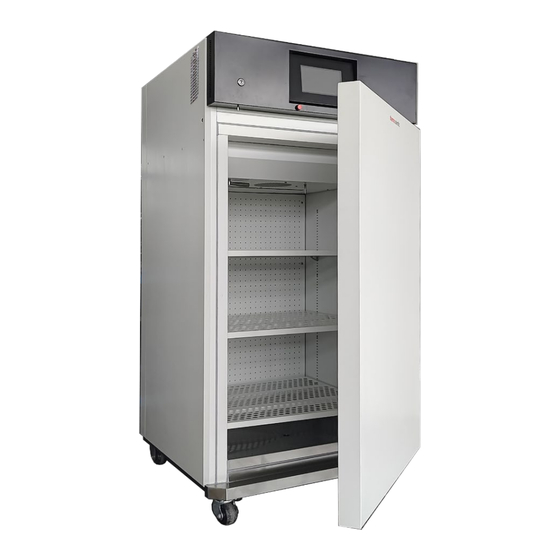
- Page 50 Chapter 5 Equipment overview and specifications Chapter 5 Equipment overview and specifications 5.1 Equipment overview Optimized for continuous operation at +37°C, +4 °C and -5 °C, perfect for incubation at +4~+37 °C. More alternatives for capacity of 150, 250, 420 and 670 L available Stepper valve hot gas by-passing and dynamic temperature control for stability up ...
- Page 51 Chapter 5 Equipment overview and specifications 5.2 Technical data TFSRI150-115V TFSRI250-115V TFSRI420-115V TFSRI720-115V Models TFSRI150-230V TFSRI250-230V TFSRI420-230V TFSRI720-230V Capacity Interior dimension (WDH) 550×450×615 550×450×1015 640×628×1050 790×628×1350 External dimension (WDH) 705×640×1215 705×640×1615 790×820×1690 940×820×1990 Package Size 800×740×1360 800×740×1770 93×950×1880 1070×950×2170 Net weight Gross weight 115±10% / 60±1% Voltage / Frequency...
- Page 52 Chapter 5 Equipment overview and specifications Shelf loading area max Cooling capacity control Stepper valve hot gas by-passing Interior material SUS 430 stainless steel powder coated white Housing materials SPCC steel with powder coating Temperature calibration ATC menu operation Communication interface RS485 Modbus RTU Display 7”...
Need help?
Do you have a question about the TFSRI Series and is the answer not in the manual?
Questions and answers