Advertisement
Available languages
Available languages
Quick Links
Advertisement

Related Manuals for Pixsys PL700


Summary of Contents for Pixsys PL700
- Page 1 PL700 Modular PLC - PLC modulare Installer manual - Manuale installatore...
- Page 3 Table of contents Safety guidelines ........................6 Organization of safety notices ................. 7 Safety Precautions ....................... 7 Precautions for safe use ....................8 Environmental policy / WEEE ..................9 Model identification ........................9 Technical data ..........................9 General characteristics ....................9 Hardware characteristics ..................10 Software characteristics ..................10 Dimensions and installation ....................10...
- Page 4 Caratteristiche software ..................24 Dimensioni ed installazione ....................24 Sequenza di montaggio dei PLC e dei moduli di espansione PLE500 ..25 Collegamenti elettrici ......................26 5.a Alimentazione ...........................26 5.b Seriale CAN1 ..........................27 Seriale COM1 come RS232 ......................27 5.d Seriale COM2 come RS485 .....................27 Seriale RS485 / COM2 ......................27 Ethernet ............................28 5.g PLE / DIN bus ..........................28...
- Page 6 Introduction PL700 is the Pixsys modular PLC CPU that integrates the Codesys Control SL v3.5 runtime programmable with the CODESYS environment. The protocols natively supported by the runtime can be expanded by activating the relevant licences (SL) that can be purchased directly from the official Codesys store.
- Page 7 Warning! damage. To maintain safety in the event of malfunction of the Digital Controller, take appropriate safety measures, such as installing a monitoring device on a separate line. PL700 - Installation manual - 7...
- Page 8 The device must be protected by a fuse 5A (cl. 9.6.2). • Wipe off any dirt from the Digital Controller with a soft dry cloth. Never use thinners, benzine, alcohol, or any cleaners that contain these or other organic 8 - PL700 - Installation manual...
- Page 9 Temperature: 0-45°C; humidity 35...95 RH% Operating conditions without condensation Container DIN43880, 54 x 90 x 64 mm Container: PC UL94V0 self-extinguishing Materials Front panel: PC UL94V0 self-extinguishing Protection IP20 (container and terminals) Weight Approx. 130 g. PL700 - Installation manual - 9...
- Page 10 500V EARTH Isolation 1 2 3 4 5 6 7 8 CAN1 COM2/485 500V EARTH Isolation 1 2 3 4 5 6 7 8 Extractable DIP2 switch DIN rail mounting guide EN50022 terminal blocks (internal) 10 - PL700 - Installation manual...
- Page 11 13 14 15 16 17 18 19 20 21 22 23 24 Proceed with mounting all the modules according to the requested order until the plc is completely formed. 500V EARTH Isolation 9 10 PL700 - Installation manual - 11...
- Page 12 The regulator is devised to be assembled with other machines. Therefore, the EC marking of the regulator does not exempt the manufacturer of the system from the safety and conformity obligations imposed for the machine as a whole. Power supply SUPPLY 12..24 VDC ± 15% 12..24Vdc 12 - PL700 - Installation manual...
- Page 13 Connect any shield of the cable to terminal 3. TXD RXD COM2 serial as RS485 Connect any shield of the cable to terminal 3. TXD RXD RS485 / COM2 serial Connect any shield of the cable to terminal 3. PL700 - Installation manual - 13...
- Page 14 CAN0 port as standard CANopen slaves. The .eds files can be found in the “documentation” section of the relevant product page at pixsys.net website. USB port (external) USB 2.0 port for Backup / Restore of the mass archiving functionalities and applications (the memory must be formatted in FAT/FAT32).
- Page 15 (the internal green LED turns on). Wait for the completion of the Backup procedure (the internal green LED turns off). Turn the PLC off, remove the MicroSD or USB memory and turn the device on again. PL700 - Installation manual - 15...
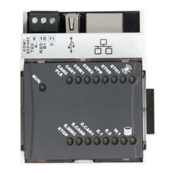
- Page 16 If set to ON, it forces the PLC’s IP address as 192.168.0.99 • If set to OFF, the IP address is 192.168.0.99 (or the last one assigned manually using the NFC antenna or the Pixsys ‘DeviceFinder’ utility). LOCK If set to ON, it enables the NFC antenna to connect with the ‘MyPixsys’...
- Page 17 The LED on indicates the presence of an error in the log or an anomaly related to Codesys runtime licences The LED on indicates the presence of activity on the PLC’s internal memory PL700 - Installation manual - 17...
- Page 18 Software’s manual The manual for the software on board the device is published online at the following link in the Manuals section: https://www.pixsys.net/en/programmable-devices/plc/pl700 Notes / Updates 18 - PL700 - Installation manual...
- Page 19 PL700 - Installation manual - 19...
- Page 20 Introduzione PL700 è la CPU del PLC modulare Pixsys che integra il runtime Codesys Control SL v3.5 programmabile con l’ambiente CODESYS. I protocolli nativamente supportati dal runtime possono essere espansi attivando le relative licenze (SL) acquistabili direttamente dallo store ufficiale Codesys.
- Page 21 Per mantenere la sicurezza, Warning! in caso di malfunzionamento, adottare misure di sicurezza appropriate; ad esempio con l’installazione di un dispositivo di monitoraggio indipendente e su una linea separata. PL700 - Manuale installatore - 21...
- Page 22 • Lo strumento deve essere protetto con un fusibile da 5A (cl. 9.6.2). • Rimuovere lo sporco dallo strumento con un panno morbido e asciutto. Non 22 - PL700 - Manuale installatore...
- Page 23 Temperatura: 0...45°C; umidità 35...95 RH% senza Condizioni operative condensa Contenitore DIN43880, 54 x 90 x 64 mm Contenitore: PC UL94V0 auto-estinguente Materiali Pannello frontale: PC UL94V0 auto-estinguente Protezione IP20 (contenitore e terminali) Peso Circa 130 g. PL700 - Manuale installatore - 23...
- Page 24 500V EARTH Isolation 1 2 3 4 5 6 7 8 CAN1 COM2/485 500V EARTH Isolation 1 2 3 4 5 6 7 8 Extractable DIP2 switch DIN rail mounting guide EN50022 terminal blocks (internal) 24 - PL700 - Manuale installatore...
- Page 25 10 11 12 13 14 15 16 17 18 19 20 21 22 23 24 Procedere con il montaggio di tutti i moduli nell’ordine richiesto fino alla completa composizione del plc. 500V EARTH Isolation 9 10 PL700 - Manuale installatore - 25...
- Page 26 Si evidenzia che il regolatore è concepito per essere assemblato ad altre macchine e dunque la marcatura CE del regolatore non esime il costruttore dell’impianto dagli obblighi di sicurezza e conformità previsti per la macchina nel suo complesso. Alimentazione SUPPLY 12..24 VDC ± 15% 12..24Vdc 26 - PL700 - Manuale installatore...
- Page 27 Collegare l’eventuale schermo del cavo al morsetto 3. TXD RXD Seriale COM2 come RS485 Collegare l’eventuale schermo del cavo al morsetto 3. Seriale RS485 / COM2 Collegare l’eventuale schermo del cavo al morsetto 3 PL700 - Manuale installatore - 27...
- Page 28 I moduli PLE500-xAD dovranno essere gestiti nel progetto Codesys sulla porta CAN0 come slave CANopen standard. I file .eds sono reperibili nella sezione “documentazione” della relativa pagina prodotto nel sito pixsys.net Porta USB (Esterna) Porta USB 2.0 per Backup / Restore degli applicativi e delle funzionalità...
- Page 29 Posizionare il DIP “Stop” su OFF e accendere il PLC premendo il pulsante (il Led verde interno si accende). Attendere il completamento della procedura di Backup (Led verde interno si spegne). Spegnere il PLC, togliere la memoria MicroSD o USB e riaccendere il device. PL700 - Manuale installatore - 29...
- Page 30 Se impostato su ON, abilita l’antenna NFC per la connessione con l’app “MyPixsys” per smartphone Android/iOS per la configurazione delle schede di rete. Se impostato su ON, mette in esecuzione il servizio interno PixsysPortal, per poter effettuare connessioni VPN al PLC. 30 - PL700 - Manuale installatore...
- Page 31 Il led acceso indica la presenza di un errore nel log o di una anomalia relativa alle licenze del runtime Codesys Il led acceso indica la presenza di attività sulla memoria interna del PLC PL700 - Manuale installatore - 31...
- Page 32 Manuale del software Il manuale del software a bordo del dispositivo è pubblicato online al link seguente nella sezione Manuali: https://www.pixsys.net/dispositivi-logica-programmabile/ plc/pl700 Note / Aggiornamenti 32 - PL700 - Manuale installatore...
- Page 33 PL700 - Manuale installatore - 33...
- Page 34 34 - PL700 - Manuale installatore...
- Page 36 Prima di utilizzare il dispositivo leggere con attenzione le informazioni di sicurezza e settaggio contenute in questo manuale. Proc. Cont. Eq. E498498 PIXSYS s.r.l. www.pixsys.net sales@pixsys.net - support@pixsys.net online assistance: http://forum.pixsys.net via Po, 16 I-30030 Mellaredo di Pianiga, VENEZIA (IT) Tel +39 041 5190518 2300.10.342-RevA...
Need help?
Do you have a question about the PL700 and is the answer not in the manual?
Questions and answers