Advertisement
Quick Links
Advertisement

Related Manuals for rotork SM-5100 Series


Summary of Contents for rotork SM-5100 Series
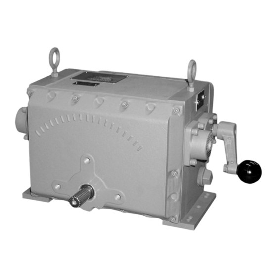
- Page 1 SM-5100 Series Instruction Manual Rotary Actuators Keeping the World Flowing...
- Page 2 Contents Section Page Section Page General Information 3–4 Parts Identification 15–17 Introduction Maintenance 18–19 Cautions Linkage Options Receiving/Inspection Major Dimensions Storage Equipment Return Identification Label Abbreviations Used in This Manual General Actuator Description Basic Models Specifications 5–6 Actuator Options Installation 7–8 Typical Wiring Diagram Start Up...
- Page 3 General Information INTRODUCTION RECEIVING/INSPECTION Rotork Controls designs, manufactures, and tests its products Carefully inspect for shipping damage. Damage to the to meet many national and international standards. For these shipping carton is usually a good indication that it has products to operate within their normal specifications, they received rough handling.
- Page 4 3.8mA. Also included is a dynamic brake circuit to increase positioning accuracy and The SM-5100 series includes 120/240 Vac single phase a looppowered, 4 to 20mA position transmitter. models, 208/240/380/480 Vac three phase models, and 24 and 90 Vdc models.
- Page 5 SM-5100 Series Specifications Rotation Mounting Up to 90° Any position. Duty Cycle Torque Limiting AC: 2,000 1% position changes/hour. Bi-Directional, disables motor in one direction when torque rating is exceeded. DC: 4,000 1% position changes/hour. Output Shaft Temperature One inch (25.4 mm) diameter with 20 tooth spline, -40 °F to 150 °F (-40 °C to 65 °C).
- Page 6 SM-5100 Series Specifications OPTION SPECIFICATIONS Auxiliary Position Limit Switches: (two or four): Servo Amplifiers 20 Amps, 250 VAC maximum, or 5 Amps at 28 VDC. All servo amplifiers include a fieldadjustable command signal Transmitter Position Feedback monitor that can be set for lock-in-place, or drive to a pre-set position if the current command signal is lost.
- Page 7 Installation MOUNTING Care, however, should be taken when driving a load to recognize that excessive output torque may be developed by The outline and mounting dimensions for a standard unit forcing the handcrank. A mechanical telltail-indicator shaft are shown on page 23 of this manual. The rear cover adjacent to the crank indicates over-torquing.
- Page 8 Installation INSTALLATION WIRING JORDAN CONTROLS SUPPLIED (OPTIONAL) COUPLING (Field Installed) Typical wiring diagrams are shown on pages 7-8. Actual wiring should follow the print supplied with the Jordan Controls has designed a three piece “wedgelock” actuator. coupling which can be adjusted to align the driven device to the actuator output shaft with no concern as to keyway The wiring diagram shows the fundamental connections for alignment of the shaft on the drive device in relation to the...
- Page 9 Typical Wiring Diagram ACTUATOR WITHOUT AN INTERNAL AMPLIFIER SM-5120 (120 VAC) SM-5140 & SM-5160 SM-5190 (240 VAC) (24 & 90 VDC) Actuator Action AC Power Applied to Terminals DC Power Applied to Terminals 1 & 2 1 & 3 1(+) & 2(-) 1(-) &...
- Page 10 Start-up ACTUATORS WITHOUT SERVO AMPLIFIERS 5. Apply motor power to drive the actuator to the desired CCW position or until PL2 trips and stops the motor. If the A. POSITION LIMIT SWITCH ADJUSTMENT driven device is not at the desired position: (Ref.
- Page 11 Start-up The fourth cam is used for any value of x between 0.5 and 2 1. Position the actuator to the desired 4mA setting. and must be cut by the user. For details on cutting this cam, 2. With potentiometer resistance at 50 ohms, adjust see “To Shape Feedback Cam”.
- Page 12 Start-up 1. Lay out on graph paper, axes and maximum and Figure 2 minimum slopes as shown in figure 2. (Maximum slope is 25 units rise per 10% shaft rotation; minimum slope is 5 units per 10% rotation.) 2. If either upper or lower shaft position is not at 0 or 100% (0°...
- Page 13 Troubleshooting Guide TROUBLE POSSIBLE CAUSE REMEDY a. No power to actuator a. Check source, fuses, wiring b. Let motor cool and determine why overheating b. Motor overheated and internal thermal switch occurred (such as, excessive duty cycle or ambient tripped (single phase AC motors only) temperature) c.
- Page 14 Troubleshooting Guide TROUBLE POSSIBLE CAUSE REMEDY a. Power not applied for other direction a. Correct power problem b. Power always applied to one direction and electrically stalls when applied for opposite b. Correct power problem direction c. Open limit switch for other direction c.
- Page 15 Parts Identification ITEM QUANTITY PART NUMBER DESCRIPTION 18B-SP1988-065 BUSHING 18B-SP1988-075 BUSHING 47A-007639-001 KNOB 54A-015023-025 SCREW RD HEAD #6-32 X .25 LG 54A-015081-150 CAP SCREW HEX HEAD .38-16 X 1.50 LG 54A-015204-038 SCREW SHOULDER SOC HD .25 X .38 LG 58B-014186-098 RET.
- Page 16 Parts Identification...
- Page 17 Parts Identification ITEM QUANTITY PART NUMBER DESCRIPTION 54A-015060-050 CAPSCREW SOC HD .25-20 x .50 LG. 60D-019010 CASTING CENTER 61B-011412-001 SUPPORT RAIL 61B-011882-001 SUPPORT RAIL 68B-018992 DRIVE GEAR ASSEMBLY 68B-038894-001 HANDLE ASSEMB;Y 68C-036204 OUTPUT SHAFT ASSEMBLY 68C-038912 AC MOTOR ASSEMBLY WITH DRAG 68D-036211 CENTER SUPPORT ASSEMBLY 68C-035819-001...
- Page 18 Maintenance LUBRICATION TORQUE LIMIT SWITCH ALIGNMENT Under normal service conditions the motor, gearing, The torque limit switches are factory set and field adjustment bearings, and parts are all pre-lubricated and should not is not advised unless proper test equipment is available. If require periodic maintenance.
- Page 19 Maintenance MOTOR REPLACEMENT FEEDBACK POTENTIOMETER REPLACEMENT 1. Disconnect all power to the actuator. A. One Turn Linear Potentiometer 1. Disconnect all power to the actuator. 2. Remove screws, washers and rear cover. 2. Remove screws, washers, and rear cover. 3. Disconnect actuator output shaft from driven device and remove actuator from mount.
- Page 20 SM-5000 Series Drive Arm and Linkage Options Notes: 1. Maximum total linkage length is specified to prevent buckling under compressive load. 2. Adjustable drive arms are also available to allow “A” length to vary from 6 to 10 inches (152 to 254 mm). In this case, the adapter-clevis has rod ball ends with lubricating fittings.
- Page 21 Major Dimensions These dimensions are subject to change without notice and should not be used for preparation of drawings or fabrication of installation mounting. Current installation dimension drawings are available on request. Keeping the World Flowing...
- Page 22 Notes...
- Page 23 Notes Keeping the World Flowing...
- Page 24 As part of a process of on-going product development, Rotork reserves the right to amend and change specifications without prior notice. Published data may be subject to change. For the very latest version release, visit our website at www.rotork.com PUB051-002-00 The name Rotork is a registered trademark.
Need help?
Do you have a question about the SM-5100 Series and is the answer not in the manual?
Questions and answers