
Subscribe to Our Youtube Channel
Related Manuals for rotork S2


Summary of Contents for rotork S2
- Page 1 SM-6000 Series Installation Manual Rotary Actuators with Local Remote Switch Redefining Flow Control...
-
Page 2: Table Of Contents
Contents Section Page Section Page Product Overview 5.1.10 - Max Pos General Information 5.1.11 - Max Torque % Specifications 5.1.12 - Save Config 2.1 - Optional Equipment 5.2 - Communications Installation 5.2.1 - HART Control Options 3.1 - Typical Wiring Diagram 5.2.2 - PROFIBUS Control Options 3.2 - Microprocessor Based Motor... -
Page 3: Product Overview
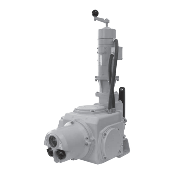
With its field-proven design, the SM-6000 S2 is a perfect fit for all of your high performance requirements. The SM-6000 S2 Series are rotary actuators internally geared to produce up to 26,000 ft. -
Page 4: General Information
Report all damage immediately to specifications, they must be properly installed and maintained. the freight carrier and Rotork Process Controls, Inc. The following instructions must be followed Unpack the product and information packet - taking care to... - Page 5 A Returned Goods authorization (RG) number is required to Ampere return any equipment for repair. This must be obtained from Alternating Current Rotork Process Controls. (Telephone: 414/461-9200) The °C Degrees Celsius equipment must be shipped, freight prepaid, to the following...
- Page 6 Rotork Process Controls product line. A local override handcrank at the rear of the motor can With the standard control electronics, they are self-contained...
-
Page 7: Specifications
2 - Specifications Output Output Shift Current Draw (A) Actuator Output Shaft Input Power Torque Speed Time at 240 vAC Input Weight Diameter volts/Ph/Hz ft. lb. (Nm) (RPM) (sec/90°) Running Stall lbs. inch 370 (502) 1.50 120-240/1-3/50-60/3@120 1.25 31.75 550 (746) 1.50 120-240/1-3/50-60/4@120 1.25... -
Page 8: Optional Equipment
2.1 - Optional Equipment • Performance: Faster speeds are available. Consult factory. • Drive Arm: Steel, for dimensions see section 10. • Mechanical Stops: A plate that bolts to the front of the actuator and limits drive arm movement is available • Relays: Customer usable relay contacts are available to detect: loss of feedback, loss of command signal, loss of power or overtorque (stall). -
Page 9: Installation
3 - Installation INSTALLATION NOTES CAUTION READ ALL INSTRUCTIONS CAREFULLY BEFORE STARTING THE INSTALLATION IN ORDER TO ACCUSTOM YOURSELF WITH THIS EqUIPMENT. FOLLOW ALL INSTRUCTIONS DURING THE INSTALLATION. DO NOT APPLY POWER UNTIL TOLD TO DO SO OR PERMANENT DAMAGE CAN RESULT. 1. - Page 10 3 - Installation cont. 5. The actuator must be securely anchored to a rigid foundation before any load is applied to the output shaft. All of the actuator mounting holes designed for anchoring must have a bolt or stud, which should be of the largest size that fits in the mounting hole (Fig.
- Page 11 3 - Installation cont. If, during local operation, electric power is restored to the actuator, the power cannot drive back through the manual handcrank and harm the operator. Upon completion of hand operation, the handcrank will spring return to its home position allowing electric operation to resume.
-
Page 12: Typical Wiring Diagram
After installation, it is required that all conduits be sealed to to the equipment will be supplied with each unit. prevent water damage and to maintain watertight NEMA 4 enclosure ratings. TYPICAL WIRING DIAGRAM Figure 3.10. Typical SM6000-S2 Wiring Diagram... -
Page 13: Microprocessor Based Motor
Shows actuator position. designed for integral local or remote mount to control • End of Travel Position Limit Switches : Switch Cams 1 appropriate Rotork Process Controls actuators. (CCW) & 2 (CW) to stop the actuator if end of travel A microprocessor-based control and an IGBT-based intelligent position is exceeded. -
Page 14: Operating Your Sm6000
4 - Operating your SM6000 Actuator WARNING Local Control Knobs Actuator may move when SPAN, ZERO or PRESET functions are selected. Display-Local Indication L P= 100 C= 100 Act Strts = 19 L P= 100 C= 100 Act Strts = 19 Figure 4.2. - Page 15 4 - Operating your SM6000 Actuator LOCAL/REMOTE SWITCH. (Fig. 4.2. C). Located on the left hand side of the electrical housing as viewed from the front. NOTE:The switch can be fitted with a padlock to prevent unauthorised operation. LOCAL MODE When the actuator is set to local mode It is possible to position the actuator using the UP/DOWN selector knob.
-
Page 16: Status Description
4.1 - Status Description STATUS DESCRIPTION In REMOTE or Local mode Line 2 of the display shows status L P= 100 C= 100 parameters when no faults are active. To cycle through the menu structure select LOCAL operation. Act Strts = 19 Using the ENTER/CANCEL selector knob it is possible to access and change parameters. -
Page 17: Start Up
4.2 - Start Up The actuator is fully tested and initially setup at the factory. The factory default settings should be used to initially commission the actuator on site. WITH POWER OFF & LOAD DISCONNECTED Verify that all wiring is correct and that the supply voltage matches the voltage shown on the actuator identification label. - Page 18 4.2 - Start Up cont. The cover assembly can now be relocated on to the left or right hand side of the gear-case to facilitate setup. Use one of the original fixings to secure the control cover assembly to the gear-case (Fig.
- Page 19 4.2 - Start Up cont. Figure 4.13 shows the front view of the electrical chassis. LOGIC CONTROL PCB Figure 4.14 shows the logic Control PCB. The PCB has one push button switch (SW1) (Fig. 4.13. A) located at right top corner of the PCB and four push button switches (SW2 to 5) located on the forward edge of the PCB.
-
Page 20: Select Automatic Mode
4.2 - Start Up cont. ENSURE THAT LOAD IS DISCONNECTED FROM ACTUATOR OUTPUT DRIvE SHAFT. SM-6060 APPLY POWER TO ACTUATOR Ver. 4.00 The actuator display should now illuminate showing actuator model and software version for 5 seconds before displaying the top menu (Fig. 4.16). Figure 4.16. - Page 21 4.2 - Start Up cont. ENTER KNOB - SELECT ‘CANCEL’ SETUP MODE Display now shows Setup Menu (Fig. 4.20). pick param Press Figure 4.20. Redefining Flow Control...
- Page 22 4.2 - Start Up cont. SAvE CONFIG pick param Save Config Figure 4.21. ENTER KNOB - SELECT ‘ENTER’ SAvING TO EEPROM pick param All changes saved to EEPROM (Fig. 4.22). All changes to Parameters will be saved when cycling of power occurs. Saving to EEPROM Figure 4.22.
-
Page 23: Range Of Operation - Setup
4.3 - Range of Operation - Setup 4.3.1 RANGE OF OPERATION The following procedure will calibrate the ZERO and SPAN limits of travel and adjustment of the Position Limit Switches if necessary. With Linkage disconnected apply power to the unit. The actuator should be in local mode to start this operation as noted in Figure 4.18. - Page 24 4.3 - Range of Operation - Setup cont. OPERATING SPEED P= 149 C= 149 The actuator output speed is factory preset to 100%. During the initial calibration of this unit it is recommended that the speed is reduced to 10% to achieve greater accuracy when Temp.
- Page 25 4.3 - Range of Operation - Setup cont. UP/DOWN KNOB - HOLD TO REDUCE SPEED Hold the UP/DOWN KNOB until the actuator speed indicates 10% (Fig. 4.35). to Speed ENT = acpt Figure 4.35. ENTER KNOB - ENTER TO SAvE vALUE Select ‘ENTER’...
- Page 26 4.3 - Range of Operation - Setup cont. ENTER KNOB - ENTER TO SAvE TO EEPROM pick param Saving to EEPROM Figure 4.38. ENTER KNOB - SELECT ‘CANCEL’ TO RETURN TO TOP MENU (Fig. 4.39). L P= 26.4 C= 26 Volt = 0 816 Figure 4.39.
-
Page 27: Set Zero And Span
4.3 - Range of Operation - Setup cont. 4.3.2 SET ZERO AND SPAN ENSURE THAT LOAD IS DISCONNECTED FROM ACTUATOR OUTPUT DRIvE SHAFT. The operating speed of the actuator is now set to 10% of rated. The ZERO and SPAN can now be set. Note: Careful attention must be used during the setting of the ZERO and SPAN of the actuator. - Page 28 4.3 - Range of Operation - Setup cont. SET ZERO POSITION The ZERO position is the position that the actuator will travel to when given its minimum command. Typically this is the closed position of the device. To set the ZERO position, follow the procedure below: ENTER KNOB - SELECT ‘CANCEL’...
- Page 29 4.3 - Range of Operation - Setup cont. Use UP/DOWN knob to move actuator output to desired ZERO position. ENTER KNOB – SELECT ‘ENTER’ TO ADjUST ZERO POSITION Whilst at the desired ZERO position - Select ‘ENTER’ to Set the new ZERO position.
- Page 30 4.3 - Range of Operation - Setup cont. SET SPAN POSITION P= 26.4 C= 26.4 The SPAN position is the position that the actuator will travel to when given its maximum command. Typically this is the open position of the device. To set the SPAN position, follow Volt = 08168 the procedure below:...
- Page 31 4.3 - Range of Operation - Setup cont. UP/DOWN KNOB - SELECT ‘SAvE CONFIG’ MENU Rotate the UP/DOWN knob until the display reads Save Config. (Fig. 4.52). pick param Save Config Figure 4.52. ENTER KNOB - ENTER TO SAvE TO EEPROM Actuator configuration must be saved to EEPROM before exiting the menu (Fig.
-
Page 32: Setting Limit Switches
4.3 - Range of Operation - Setup cont. 4.3.3 SETTING LIMIT SWITCHES SET INCREASING POSITION LIMIT SWITCH CAM#1 It is now possible to set the CW & ACW position limit switches. With actuator set to LOCAL mode (see section 4.2) move output shaft to the ACW end of travel position. - Page 33 4.3 - Range of Operation - Setup cont. SET ADDITIONAL LIMIT SWITCHES (If fitted) Repeat the procedure for switches CAM #3 to #6 as required. REFIT TOP AND SIDE COvERS Check condition of o-ring seals (replace if necessary) and refit cover assemblies.
-
Page 34: Operating Speed
4.3 - Range of Operation - Setup cont. 4.3.4 OPERATING SPEED P= 149 C= 149 The actuator output speed can now be changed to suit the process requirement. Temp. C 32 27 To change the actuator speed. Figure 4.60. ENTER KNOB - SELECT ‘CANCEL’ pick param Ctrl Type = Man Figure 4.61. - Page 35 4.3 - Range of Operation - Setup cont. ENTER KNOB - ENTER TO SAvE vALUE Set new speed setting. NOTE: CYCLING THE POWER TO THE ACTUATOR to Speed AT THIS STAGE WILL REMOvE RECENT CHANGES. ENT = acpt Figure 4.63. TO AvOID LOSS OF SETTINGS USE UP/DOWN KNOB TO SCROLL TO THE ‘SAvE CONFIG‘...
-
Page 36: Setup & Calibration
SECT 5.1 SETUP & CALIBRATION tuning of the actuator operation. Level 2: Diagnostic and Advanced Settings (Section 5.3). SECT 5.2 COMMUNICATIONS User may wish to consult Rotork Process Controls before making changes to level 2 parameters. LEvEL 1 MENU STRUCTURE SETUP MODE... -
Page 37: Setup & Calibration - Level
5.1 - Setup and Calibration - Level 1 WARNING: SETTING THE OUTPUT TORqUE HIGHER NOTE: THAN 100% RATED MAY RESULT IN DAMAGE TO THE CYCLING THE POWER TO THE ACTUATOR AT THIS ACTUATOR AND OR LINKAGE. STAGE WILL REMOvE RECENT CHANGES. TO AvOID LOSS OF SETTINGS USE UP/DOWN KNOB TO SCROLL TO THE ‘SAvE CONFIG‘... -
Page 38: Max Cmd Cal
5.1 - Setup and Calibration - Level 1 cont. 5.1.1 MAX CMD CAL Used to calibrate the analogue command signal to the desired MAX position. This maximises resolution and optimises accuracy. The analogue control signal should be applied to terminals as follows. Voltage TB2-1 (+ve) TB2-2 (-ve) Current TB2-4 (+ve) TB2-3 (-ve) pick param... -
Page 39: Speed
5.1 - Setup and Calibration - Level 1 cont. 5.1.3 SPEED The actuator output speed is adjustable from 1 - 100% of its rated value. 1 - Enter setup mode (see section 4.2). 2 - Use the UP/DOWN knob to scroll through menus until ‘Speed = XXX‘ appears on line 2 of the display. -
Page 40: Los Pos
5.1 - Setup and Calibration - Level 1 cont. 5.1.6 LOS POS Used to determine the position that the actuator will move to on loss of analogue control signal. 1 - Enter setup mode (see section 4.2). 2 - Use UP/DOWN knob until LOS POS is displayed. 3 - Select ‘ENTER’. -
Page 41: Min Pos
5.1 - Setup and Calibration - Level 1 cont. 5.1.9 MIN POS Used to set the position regarded as ZERO when limited range positioning is required. Only applicable when the FB Pos Limit is active. For example if MIN POS is set to 10% this is reported as the ZERO (0%) position. -
Page 42: Max Torque
5.1 - Setup and Calibration - Level 1 cont. 5.1.11 MAX TORqUE % Used to limit the output torque produced by the actuator. Exceeding the value will result in an over torque alarm being displayed. 1 - Enter setup mode (see section 4.2). 2 - Use UP/DOWN knob until Max TORQUE is displayed. -
Page 43: Communications
5.2 - Communications COMMS OPT HART Used to select specific menus when a BUS communications option card is fitted. CTRL HART 1 - Enter setup mode (see section 4.2). MECH ADDR LOS ACT LOS P LOS TO 2 - Use UP/DOWN knob until COMS OPT is displayed. Figure 5.18 3 - Select ‘ENTER’. - Page 44 5.2 - Communications cont. COM LOS ACT Action on loss of HART communication. 1 - Enter setup mode (see section 4.2). 2 - Use UP/DOWN knob until COM LOS ACT is displayed. 3 - Select ‘ENTER’. 4 - Use UP/DOWN knob to select the desired action. Menu choices are: LOCK - Stayput or Lock in place.
-
Page 45: Profibus Control Options
5.2 - Communications cont. 5.2.2 PROFIBUS CONTROL OPTIONS PROFIBUS CTRL MECH The actuator can be controlled via commands received over CTRL PROFI FB POS MECH ADDR LOS ACT LOS P LOS TO the Profibus protocol communications channel or as a direct analogue (4-20 mA) input signal request. - Page 46 5.2 - Communications cont. COM LOS ACT Action on loss of Profibus communication. 1 - Enter setup mode (see section 4.2). 2 - Use UP/DOWN knob until COM LOS ACT is displayed. 3 - Select ‘ENTER’. 4 - Use UP/DOWN knob to select the desired action. Menu choices are: LOCK - Stayput or Lock in place.
-
Page 47: Foundation Fieldbus
5.2 - Communications cont. 5.2.3 FOUNDATION FIELDBUS FFBUS CONTROL OPTIONS CTRL MECH CTRL FB POS The actuator can be controlled via commands received over MECH LOS ACT LOS P LOS TO the FFBUS protocol communications channel or as a direct analogue (4-20 mA) input signal request. - Page 48 5.2 - Communications cont. COMM LOS P Position actuator will move to on loss of FFBUS communication. 1 - Enter setup mode (see section 4.2). 2 - Use UP/DOWN knob until COM LOS P is displayed. 3 - Select ’ENTER’ 4 - Use UP/DOWN knob to select the desired position.
-
Page 49: Setup And Calibration - Level 2
5.3 - Setup and Calibration - Level 2 SM-6000 S2 MENU STRUCTURE Level 2: Diagnostic and Advanced Settings. User may wish to consult Rotork Process Controls before making changes to level 2 parameters. SETUP MODE LEvEL 2 MOTOR MAX TORqUE... -
Page 50: Motor Pwm
5.3 - Setup and Calibration - Level 2 cont. LEvEL 2 ADvANCED SETUP MENUS CAUTION: SOME vARIABLES IN LEvEL 2 ARE FACTORY SET – DO NOT ADjUST!! 5.3.1 MOTOR PWM Command used to represent motor speed in function of maximum pulse width modulation. To access the advanced setup and calibration menus rotate the UP/DOWN knob clockwise and the ENTER/CANCEL knob anti-clockwise. -
Page 51: Loop
5.3 - Setup and Calibration - Level 2 cont. 5.3.6 LOOP Closed loop or Open loop control. The default setting of the actuator is Closed loop control. Open loop is used for factory setup only. This value is factory set and must not be changed. pick param Loop = Run Figure 5.42. -
Page 52: Faults & Troubleshooting
6 - Faults & Troubleshooting 6.1 FAULT STATUS INDICATION Fault Diagnostics appear on line two of the display. When more than one diagnostic is active, only the highest priority will show. Flt: Incr Limit Flt: LOS-Feedbk End of Travel Limit Switch for the increasing direction is If using an encoder, either the encoder is disconnected, the tripped. -
Page 53: Troubleshooting
6 - Faults & Troubleshooting cont. 6.2 TROUBLESHOOTING Trouble Possible Cause Remedy LS2 is tripped Actuator will increase position but Increase actuator to normal operating not decrease range. Check LS2 and Zero Setup Actuator is at zero position Actuator will decrease position, Decrease actuator to normal operating LS1 is tripped but not increase... -
Page 54: Local Operation - Handcrank Direction
7 - Local Operation - Handcrank Direction Rotation Rotation of Output Shaft Speed/Torque of Handcrank (looking at the end of the output shaft) 10/370 10/550 10/800 10/1400 10/2500 10/4400 10/6200 12/8000 18/11000 26/16500 42/26000... -
Page 55: Mounting Conversion
8 - Mounting Conversion On the 5 largest units with two reservoirs relocate the To convert a Horizontally mounted SM-6000 to a vertically mounted SM-6000: breathers from both reservoirs as noted above. • Unthread the existing breather located near the top To convert a Vertical SM-6000 to a Horizontal SM-6000 follow same steps but do not remove lubricant. -
Page 56: Parts Identification
9 - Parts Identification 370, 800 & 1400 ft. lb. units... - Page 57 9 - Parts Identification cont. 2500 ft. lb. unit SM6000 publication P5XXE ver 1.02 24 Aug 09 revised for V3.08 Firmware Redefining Flow Control...
- Page 58 9 - Parts Identification cont. 4400, 6200, 8000, 11000, 16500, & 26000 ft. lb. units SM6000 publication P5XXE ver 1.02 24 Aug 09 revised for V3.08 Firmware...
-
Page 59: Drive Arm Dimensions
7.75 6.08 1.25 2.00 – These dimensions are subject to change without notice and should not be used for preparation of drawings or fabrication of installation mounting. For current installation manuals and other product information, see www.rotork.com. Redefining Flow Control... -
Page 60: Overall Dimensions
1.97 1.30Ø 5.500/5.499Ø 1.25 x 1.25 KEY 8.00 These dimensions are subject to change without notice and should not be used for preparation of drawings or fabrication of installation mounting. For current installation manuals and other product information, see www.rotork.com. -
Page 61: Linkage Options
12 - Linkage Options Notes: 1. Maximum total linkage length is specified to prevent buckling under compressive load. 2. Special drive arm lengths are available to meet application requirements. “A” LENGTH “B” MAXIMUM “F” DIA. HOLE “C” LENGTH “D” LENGTH “E”... -
Page 62: User Settings
13 - User Settings Span Zero Max.Cal.: Min. Cal.: Speed: Cmd Type: Cntrl Mech: Comms Settings: LOS Action: P Gain: I Gain: Min Pos Max Pos Max. Torque (%): Max. Torque (ft. lbs.): Input volts (tp amp from transformer): Motor Rating: Password: Loop: Open Closed... -
Page 63: Notes
Notes Redefining Flow Control... - Page 64 As part of a process of on-going product development, Rotork reserves the right to amend and change specifications without prior notice. Published data may be subject to change. For the very latest version release, visit our website at www.rotork.com PUB052-003-00 The name Rotork is a registered trademark.
Need help?
Do you have a question about the S2 and is the answer not in the manual?
Questions and answers