Advertisement
Quick Links
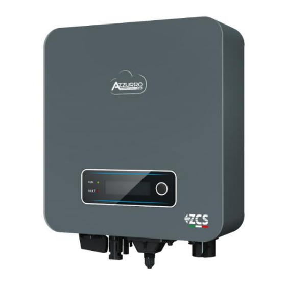
Grid-connected inverter
1PH 1100TL-3300TL-V3
Zucchetti Centro Sistemi S.p.A. - Green Innovation Division
Via Lungarno, 248 - 52028 Terranuova Bracciolini - Arezzo, Italy
tel. +39 055 91971 - fax. +39 055 9197515
innovation@zcscompany.com - zcs@pec.it – www.zcsazzurro.com
Reg. Pile IT12110P00002965 - Share Capital € 100,000.00 fully paid up
Reg. Impr. AR n.03225010481 - REA AR - 94189
ISO 9001 Certified Company - Certificate no. 9151 - CNS0 - IT-17778
All manuals and user guides at all-guides.com
User Manual
Advertisement

Related Manuals for ZUCCHETTI ZCS 1PH 1100TL-V3


Summary of Contents for ZUCCHETTI ZCS 1PH 1100TL-V3
- Page 1 All manuals and user guides at all-guides.com Grid-connected inverter 1PH 1100TL-3300TL-V3 User Manual Zucchetti Centro Sistemi S.p.A. - Green Innovation Division Via Lungarno, 248 - 52028 Terranuova Bracciolini - Arezzo, Italy tel. +39 055 91971 - fax. +39 055 9197515 innovation@zcscompany.com - zcs@pec.it – www.zcsazzurro.com Reg.
- Page 2 All manuals and user guides at all-guides.com Table of Contents Preliminary safety instructions ................................7 1.1. Safety instructions ..................................7 1.2. Symbols and icons .................................. 10 Product features ......................................12 2.1. Product presentation ................................12 2.2. Description of functions ..............................14 2.3. Efficiency curve ..................................
- Page 3 All manuals and user guides at all-guides.com Troubleshooting and maintenance ..............................62 7.1. Troubleshooting ..................................62 7.2. Maintenance ..................................... 70 Uninstalling ........................................71 8.1. Uninstallation steps ................................71 8.2. Packaging ....................................71 8.3. Storage ......................................71 8.4. Disposal ...................................... 71 Technical specifications ..................................
- Page 4 Copyright statement Copyright of this manual belongs to Zucchetti Centro Sistemi S.p.A. No part of this manual (including the software, etc.) may be copied, reproduced or distributed in any form or by any means without the permission of Zucchetti Centro Sistemi S.p.A.
- Page 5 All manuals and user guides at all-guides.com Preface General information Please read this manual carefully before installation, operation or maintenance. This manual contains important safety instructions that must be followed during installation and maintenance of the system. Scope This manual describes the assembly, installation, electrical connections, commissioning, maintenance and troubleshooting of the following AZZURRO inverters: 1PH 1100TL-V3 / 1PH 1600TL-V3 / 1PH 2200TL-V3 / 1PH 2700TL-V3 / 1PH 3000TL-V3 / 1PH 3300TL-V3...
- Page 6 All manuals and user guides at all-guides.com Danger: indicates a hazardous situation which, if not resolved or avoided, could result in serious personal injury or death. Danger Warning: indicates a hazardous situation which, if not resolved or avoided, could result in serious personal injury or death. Warning Caution: indicates a hazardous situation which, if not resolved or avoided, could result in minor or moderate personal injury.
- Page 7 For safety reasons, this inverter can only be installed by a qualified electrician with the necessary training and/or skills and knowledge. Zucchetti Centro Sistemi S.p.A. declines all responsibility for damage to property or personal injury caused by incorrect use of the device.
- Page 8 If necessary, request assistance from an installer of photovoltaic systems or from Zucchetti Centro Sistemi SpA. Transport of the equipment, especially by road, must be carried out with vehicles suitable to protect the components (in particular, electronic components) against violent knocks, humidity, vibrations, etc.
- Page 9 All manuals and user guides at all-guides.com All installation operations must be carried out by a professional electrician, who must: be prepared. carefully read this manual and understand its contents. Warning Before connecting the inverter to the grid, make sure that all the necessary permits have been obtained from the local grid operator and that all the electrical connections are made by a professional electrician.
- Page 10 Do not disassemble the internal components of the inverter without permission. This will void the warranty. Zucchetti Centro Sistemi S.p.A. shall not be responsible for any damage or loss caused by improper use or maintenance Attention 1.2.
- Page 11 All manuals and user guides at all-guides.com Symbols on the inverter Some safety symbols are located on the inverter. Read and understand the contents of the symbols before installing the inverter. Residual voltage may be present on the inverter! Before opening the inverter, wait 5 minutes to ensure that the capacitors are completely discharged.
- Page 12 All manuals and user guides at all-guides.com 2. Product features General information in this chapter Product dimensions The field of use and overall dimensions of the 1PH 1100TL-3300TL-V3 inverters are indicated in this section. Description of functions Describes how the 1PH 1100TL-3300TL-V3 inverters and their internal operating modules work. Efficiency curve Describes the efficiency curves of the inverter.
- Page 13 All manuals and user guides at all-guides.com Figure 3 – Front, side and back view of the inverter and bracket • Overall dimensions 1PH 2700TL-3300TL-V3 : LxWxH = 321 mm x 260.5 mm x 131.5 mm Figure 4 – Front, side and back view of the inverter and bracket 13 / 103 User’s Manual 1PH 1100TL-3300TL-V3 Rev.
- Page 14 All manuals and user guides at all-guides.com Labels on the inverter Figure 5 – Do not remove the label on the side of the inverter 2.2. Description of functions The DC power generated by the PV modules is filtered through the input board before entering the power board.
- Page 15 All manuals and user guides at all-guides.com C. Automatic power reduction when grid is over frequency When the grid frequency is higher than the limit set, the inverter reduces the output power in order to ensure the stability of the grid. D.
- Page 16 All manuals and user guides at all-guides.com 2.3. Efficiency curve Efficiency curve for an Azzurro ZCS 1PH 3300 TL-V3 model Figure 7 – Efficiency curve for an Azzurro ZCS 1PH 3300TL-V3 inverter 16 / 103 User’s Manual 1PH 1100TL-3300TL-V3 Rev. 1.1 12/03/2021 Identification: MD-AL-GI-00 Rev.
- Page 17 All manuals and user guides at all-guides.com 3. Installation General information in this chapter This chapter describes how to install the 1PH 1100TL- 3300TL-V3 inverter. Installation notes: DO NOT install 1PH 1100TL-3300TL-V3 inverters near flammable materials. DO NOT install 1PH 1100TL-3300TL-V3 inverters in an area where flammable or Danger explosive materials are stored.
- Page 18 All manuals and user guides at all-guides.com damage such as holes or tears. If any form of damage is detected, do not open the box containing the inverter and contact the supplier and the courier as soon as possible. It is recommended to remove the packaged materials from the box 24 hours before installing the inverter. Checking the product After removing the inverter from its packaging, check that the product is intact and complete.
- Page 19 All manuals and user guides at all-guides.com 1 Warranty Outgoing inspection Registration 1 AC output connector 1 485 terminal report 3.3. Installation tools The following tools are required for installation of the inverter and electrical connections; therefore, they must be prepared before installation. Tool Function Drill...
- Page 20 All manuals and user guides at all-guides.com To screw the inverter to the wall-mounting bracket and to 4 mm Allen key open the front cover of the inverter To crimp the RJ45 connectors RJ45 crimping tool for the communication cables To insert the expansion plugs Rubber hammer into the wall holes...
- Page 21 All manuals and user guides at all-guides.com Measuring tape To measure distances Level To make sure the bracket is level ESD gloves Protective clothing Safety goggles Protective clothing Protection mask Protective clothing 3.4. Installation position Choose an appropriate installation location for the inverter. Follow the requirements below to determine the installation position.
- Page 22 All manuals and user guides at all-guides.com Figure 9 – Requirements or installing a single inverter Figure 10 – Requirements for installing multiple inverters For safety reasons, ZCS Spa and/or its partners may not carry out any technical repairs or maintenance work, or move the inverter from and to the ground if it is installed at a height of more than 180 cm from the ground.
- Page 23 All manuals and user guides at all-guides.com 3.5. Moving the 1PH 1100TL-3300TL-V3 inverter This section describes how to move the inverter correctly Open the packaging and remove the protective cover in polystyrene, insert your hands into the slots on both sides of the inverter and take a hold of it, as shown in figures 11 and 12. Figure 11 –...
- Page 24 All manuals and user guides at all-guides.com holes using a suitable marker pen. Keeping the hammer drill perpendicular to the wall and avoiding any sudden movements when drilling, drill the 3 holes at the points marked on the wall using a 6 mm drill bit. In case of errors during drilling, it is necessary to reposition the holes.
- Page 25 All manuals and user guides at all-guides.com 4. Electrical connections General information in this chapter This chapter describes the electrical connections of the 1PH 1100TL-3300TL-V3 inverter. Carefully read this section before connecting the cables. NOTE: Before making any electrical connections, ensure that the DC circuit breaker is switched off. Please note that the capacitors in the inverter may remain electrically charged after the DC circuit breaker has been switched off.
- Page 26 All manuals and user guides at all-guides.com 4.1. Electrical connections Figure 14 – Steps for connecting the cables 4.2. Ground cable connections (PGND) Connect the 1PH 1100TL-3300TL-V3 inverter to the ground electrode using ground protection cables (PGND). The inverter does not have a transformer, therefore the positive and negative polarities of the photovoltaic string do NOT need to be grounded.
- Page 27 All manuals and user guides at all-guides.com Figure 15 – Preparing the ground cable (1) 1. Insert the exposed wires in the OT terminal and crimp them using a crimping tool, as shown in Figure 16. Note 1: L3 is the length between the insulation layer of the ground cable and the crimped part. L4 is the distance between the crimped part and the conductor wires protruding from the crimped part.
- Page 28 All manuals and user guides at all-guides.com Figure 17 – Connecting the ground terminal 4.3. Connecting the DC input power cables Connect the 1PH 2700TL-3300TL-V3 inverter to the photovoltaic strings using DC input power cables. Note Depending on the type of inverter, select the appropriate inverter accessories (cables, fuse holder, fuse, switch, etc).
- Page 29 All manuals and user guides at all-guides.com Before connecting the power supply, be sure to disconnect the generator’s DC switch. When exposed to the sun, the photovoltaic generator produces a voltage that can be dangerous! Before connecting the power supply, make sure that the voltage of the DC cables is within the permissible operating range and that the DC circuit Danger breaker switch is open.
- Page 30 All manuals and user guides at all-guides.com Figure 18 – Positive (1) and Negative (2) MC4 connectors Note: The positive and negative metal terminals are packed together with the positive and negative connectors respectively. Separate the positive and negative metal terminals after unpacking the inverter so as to avoid confusing the polarities.
- Page 31 All manuals and user guides at all-guides.com Figure 20 - Connecting the DC input power cables (2) 5) Insert the crimped power cables in the corresponding seats until you hear a “click” sound. At that point, the power cables will snap into place. 6) Replace the cable glands on the positive and negative connectors and rotate them against the insulation covers.
- Page 32 All manuals and user guides at all-guides.com Figure 22 – Removing the DC connector 4.4. Connecting the AC output power cables Connect the inverter to the AC power distribution network or power grid using AC power cables. Do not use the same AC circuit breaker for multiple inverters.
- Page 33 All manuals and user guides at all-guides.com Note: For safety reasons, make sure to use suitably sized cables, otherwise the current may cause overheating or overloading, which could result in a fire. Figure 23 – Do not connect loads between the inverter and circuit breaker Multi-core copper cables The cross-section of the power line must be sized in order to prevent unwanted disconnections of the inverter from the grid due to high...
- Page 34 All manuals and user guides at all-guides.com Figure 24 – Relationship between power loss, length and cable cross-section The 1PH 11100TL– 3300TL-V3 inverters are single-phase output inverters that fully comply with the local grid connection requirements and safety standards. The inverters are equipped with AC output connectors with IP66 protection suitable for photovoltaic use; the installer of the system is responsible for connecting the AC output cable;...
- Page 35 All manuals and user guides at all-guides.com Cable connection procedure 1) Identify the suitable cables as shown in table 2 and remove an appropriate length of the protective sheath, as shown in the figure (A: 30~50 mm B: 6~8 m). Figure 26 - Connecting the AC output cables (1) 2) Disassemble the AC connector as shown in the figure below;...
- Page 36 All manuals and user guides at all-guides.com Figure 28 - Connecting the AC output cables (3) 4) Secure the clamping cable gland by rotating it in a clockwise direction, as shown below; make sure that all the wires are securely connected 5) Connect the AC output connector to the output terminal of the inverter;...
- Page 37 All manuals and user guides at all-guides.com Make sure the grid is correctly disconnected before removing the AC connector. Warning 4.5. Connecting the communication cables The figure below shows the arrangement of the communication ports on the inverters 1PH 1100TL - 3300TL-V3. Figure 31 - Arrangement of communication ports Connecting the communication port Note: The wiring procedure is the same for the RS485 input, I/O input and CT input.
- Page 38 All manuals and user guides at all-guides.com 1) Remove the central waterproof cover of the communication terminal block using a star screwdriver; Figure 32 – Removing the central cover 2) Turn the waterproof cable gland; remove the cap in the waterproof cable gland; Figure 33 –...
- Page 39 All manuals and user guides at all-guides.com Type RS485 Connector Label Function RS485 differential signal - RS485 differential signal + Table 4 – Description of the communication terminals and their function Figure 34 – Tightening the terminals on the cables 5) Insert the terminal according to the printed label, then tighten the screws to secure the waterproof cover;...
- Page 40 All manuals and user guides at all-guides.com Figure 36 – Closing the central door 40 / 103 User’s Manual 1PH 1100TL-3300TL-V3 Rev. 1.1 12/03/2021 Identification: MD-AL-GI-00 Rev. 1.1 of 12/03/2021 - Application: GID...
- Page 41 If in doubt, consult the system engineer or a qualified electrician. Zucchetti Centro Sistemi S.p.A. shall not be held responsible for any consequences resulting from the incorrect selection of the country code. 41 / 103 User’s Manual 1PH 1100TL-3300TL-V3...
- Page 42 All manuals and user guides at all-guides.com If the inverter indicates the presence of any faults, refer to chapter 7.1 of this manual or contact the Zucchetti Centro Sistemi S.p.A. technical support. 42 / 103 User’s Manual 1PH 1100TL-3300TL-V3 Rev. 1.1 12/03/2021 Identification: MD-AL-GI-00 Rev.
- Page 43 All manuals and user guides at all-guides.com 6. Operating interface General information in this chapter This section describes the display and its operation, as well as the buttons and LED indicators of the 1.1K- 3.3K TL inverters. 6.1. Operating panel and display Buttons and LED indicators Figure 37 –...
- Page 44 All manuals and user guides at all-guides.com Warning light (RED) o Steady: temporary or permanent error o Off: normal operation 6.2. Main interface Below are some examples of the main screen, obtained by short pressing the key. Voltage and current present on the channel AC grid voltage and AC current produced ...
- Page 45 All manuals and user guides at all-guides.com At start up, the LCD screen displays “ZCS INNOVATION...,” as shown in the figure below, when the control board is correctly connected to the communication board, the LCD display will show the current status of the inverter, as shown in the figure below.
- Page 46 All manuals and user guides at all-guides.com Permanent error: the inverter has encountered a permanent error. The installer must debug this type of error according to the code found in order to bring the inverter back to its proper functioning. If the control board and communication board are not connected, the interface of the LCD display appears as shown in the figure below.
- Page 47 All manuals and user guides at all-guides.com Press the key for 3 seconds to enter the “Settings” menu. When the country code is set at 01 (CEI0-21 Internal), the “Settings” menu shows the following sub- menu: Short press the key to go to the next item of the menu. 1.
- Page 48 All manuals and user guides at all-guides.com 4. Set Country Select “4. Set Country” and long press the key to enter the menu for setting the national grid regulations. If “Setting disabled” appears, go to point “7. Enable Country” to enable this function. Once the function has been enabled, repeat the above steps and set the code relating to the desired national regulations.
- Page 49 All manuals and user guides at all-guides.com Italy CEI 0-16 CEI 0-21 Areti AU-VIC UK-G83 Ukraine Table 5 – Country Codes 5. Enable country Select “7. Enable country” and long press the key to enter the menu for enabling this country code. The display will show “Enter PWD!”;...
- Page 50 The user can change the start parameters directly from the LCD display. The user must first copy the TXT files to the SD card. These files can be requested from Zucchetti Centro Sistemi Spa technical support. Select “11. InitParameters” and long press the key to enter the menu for setting the start parameters. The display will show “Enter PWD!”;...
- Page 51 All manuals and user guides at all-guides.com 12. Insulation The user can change the value of the insulation resistance directly from the LCD display. The user must first copy the TXT files to the SD card. These files can be requested from ZCS technical support. Select “14.
- Page 52 All manuals and user guides at all-guides.com point, short press the key to select the option “1.Enable” or “2.Disable” and confirm the selection by long pressing the key. If the “1.Enable” option is selected, short press the key to select the value (expressed in kW, up to two decimal places) of the maximum power that the inverter will feed into the grid.
- Page 53 All manuals and user guides at all-guides.com 53 / 103 User’s Manual 1PH 1100TL-3300TL-V3 Rev. 1.1 12/03/2021 Identification: MD-AL-GI-00 Rev. 1.1 of 12/03/2021 - Application: GID...
- Page 54 All manuals and user guides at all-guides.com 17. Standard Self-test 1) During normal operation of the inverter, long press the key to enter the main menu. 2) Long press the key again to enter the “Settings” menu. 3) Short press the key several times until “20. STD self-test” is displayed on the screen. 4) Long press the key to start the self-test.
- Page 55 All manuals and user guides at all-guides.com 55 / 103 User’s Manual 1PH 1100TL-3300TL-V3 Rev. 1.1 12/03/2021 Identification: MD-AL-GI-00 Rev. 1.1 of 12/03/2021 - Application: GID...
- Page 56 All manuals and user guides at all-guides.com 18. P(f) Setting Select “21. Set P(f)” and long press the key to enter the relative menu, from which you can change the active power according to the grid frequency required by the local regulations. This function may be required by various regulations for grid-connected inverters.
- Page 57 All manuals and user guides at all-guides.com 21. Disabled settings The following functions: Remote Control, relating to item “5. Remote Control” Relay Command, relating to item “6. Relay Command” Relay test, relating to item “15. Relay Test they cannot be used on this model of inverter; access to these submenus is not permitted either by the installer or by the end user.
- Page 58 All manuals and user guides at all-guides.com From the “System Info” menu, short press the key to move it, and hold it down for a few seconds to enter the menu “1. Inverter type.” Here you can see the power of the inverter model ...
- Page 59 All manuals and user guides at all-guides.com Long press the key to enter the “Date and time” menu. Long press the key in the main interface and then short press to enter the submenu “4. Date and Time”, then press the key again to display the current date and time set on the inverter. Long press the key to enter the “Update Software”...
- Page 60 All manuals and user guides at all-guides.com The complete and detailed procedure for updating the firmware is described below. Update requirements USB device (stick) at least 2 GB PC with USB port Firmware update procedure 1. Switch off the ZCS inverter by first disconnecting the AC power supply via the switch installed on the system, and then disconnecting the DC power supply via the switch located on the side of the inverter or switch off the system’s disconnecting switch.
- Page 61 All manuals and user guides at all-guides.com DSP1 Update DSP2 Update ARM Update 9. Check that the inverter completes the update correctly and that “ZCS INNOVATION” appears on the display; the inverter will then start normally. If the update was not successful, one of the following messages will appear on the display: “Commun Err”, “UPDATE DSP1 FAIL”...
- Page 62 All manuals and user guides at all-guides.com 7. Troubleshooting and maintenance 7.1. Troubleshooting This section contains information and procedures on how to troubleshoot any faults and errors that may occur during operation of the 1PH 2700TL-3300TL-V3 inverter. If you have any problems with the inverter, please follow these steps. ...
- Page 63 All manuals and user guides at all-guides.com its normal state. The grid frequency is ID03 GridOFP too high. If the alarm occurs frequently, check whether the grid voltage/frequency is within the correct range. If not, contact technical support. If so, check the AC circuit breaker and the AC wiring of the inverter.
- Page 64 All manuals and user guides at all-guides.com of the inverter. The inverter automatically returns to its normal operating state after the string has been corrected. Check the configuration of the input ID10 IpvUnbalance The input current is mode (parallel mode / independent unbalanced.
- Page 65 All manuals and user guides at all-guides.com The grid current is that the fault is no longer present. If ID16 AcRmsOCP too high. this is not the case, contact Technical Support. Sampling error of the ID17 HwADFaultIGrid grid current ID18 HwADFaultDCI DCI sampling error Sampling error of the...
- Page 66 All manuals and user guides at all-guides.com according to Section 6.3 (A) “10. Configuration of input mode” of this manual. If the input mode is correct, turn off the DC disconnecting switch and wait 5 minutes, then turn on the DC disconnecting switch again.
- Page 67 All manuals and user guides at all-guides.com The current sampling value of the automatic differential circuit ID52 ConsistentFault_GFCI breaker (GFCI) between the master DSP and the slave DSP is not the same. SPI communication error between the ID53 SpiCommLose master DSP and the slave DSP.
- Page 68 All manuals and user guides at all-guides.com The grid current is Support. not balanced and has ID67 UnrecoverIacRmsUnbalance caused an irreparable fault. The input current is not balanced and has ID68 UnrecoverIpvUnbalance caused an irreparable fault. The bus voltage is not balanced and has ID69 UnrecoverVbusUnbalance...
- Page 69 All manuals and user guides at all-guides.com The relay has ID77 UnrecoverRelayFail generated a permanent fault. Make sure that the installation position and the installation method meet the requirements of Section 3.4 The inverter has been of this manual. derated because the ID81 OverTempDerating Check if the ambient temperature in...
- Page 70 All manuals and user guides at all-guides.com do not match. ID95-ID96 are internal faults of the The EEPROM Faulty EEPROM inverter; turn off the DC ID95 communication board communication board. is faulty. disconnecting switch and wait 5 minutes, then turn on the DC disconnecting switch again.
- Page 71 8.4. Disposal Zucchetti Centro Sistemi S.p.a. is not liable for the disposal of the equipment, or parts thereof, that does not take place according to the regulations and standards in force in the country of installation. The symbol of the crossed-out wheeled bin indicates that the equipment, at the end of its useful life, must be disposed of separately from household waste.
- Page 72 All manuals and user guides at all-guides.com 9. Technical specifications TECHNICAL DATA 1100TL-V3 1600TL-V3 2200TL-V3 2700TL-V3 3000TL-V3 3300TL-V3 72 / 103 User’s Manual 1PH 1100TL-3300TL-V3 Rev. 1.1 12/03/2021 Identification: MD-AL-GI-00 Rev. 1.1 of 12/03/2021 - Application: GID...
- Page 73 All manuals and user guides at all-guides.com 10. Monitoring systems 10.1. External Wi-Fi adapter 10.1.1. Installation Unlike the internal Wi-Fi card, the external adapter must be installed for all compatible inverters. However, the procedure is quicker and easier as there is no need to open the front cover of the inverter. In order to monitor the inverter, the RS485 communication address must be set to 01 directly from the display.
- Page 74 All manuals and user guides at all-guides.com 3) Connect the Wi-Fi adapter to the appropriate port, making sure to follow the direction of the connection and ensure correct contact between the two parts. Figure 40 – Inserting and securing the external Wi-Fi adapter 4) Switch on the inverter by following the procedure described in the manual.
- Page 75 All manuals and user guides at all-guides.com If the Wi-Fi signal does not reach the inverter, a system must be installed to amplify the signal and bring it to the installation location. 1) Activate the search for the Wi-Fi networks on your telephone or PC so that all the networks visible by your device are displayed.
- Page 76 All manuals and user guides at all-guides.com 2) Connect to a Wi-Fi network generated by the inverter's Wi-Fi adapter (i.e. AP_*******, where ******* indicates the serial number of the Wi-Fi adapter shown on the label of the device), which operates as an access point.
- Page 77 All manuals and user guides at all-guides.com Figure 44 – Password of external Wi-Fi adapter Note: To ensure that the adapter is connected to the PC or smartphone during the configuration procedure, enable automatic reconnection of the AP_******* network. Figure 45 – Password entry prompt 77 / 103 User’s Manual 1PH 1100TL-3300TL-V3 Rev.
- Page 78 All manuals and user guides at all-guides.com Note: the Access Point is not able to provide internet access; confirm to maintain the Wi-Fi connection, even if the internet is not available Figure 46 – Screen indicating that the Internet cannot be accessed 4) Open a browser (Google Chrome, Safari, Firefox) and enter the IP address 10.10.100.254 in the address bar at the top of the screen.
- Page 79 All manuals and user guides at all-guides.com 5) The status screen will open, showing the logger information such as the serial number and firmware version. Check that the Inverter Information fields are filled in with the inverter information. The language of the page can be changed using the command in the top right-hand corner. Figure 48 –...
- Page 80 All manuals and user guides at all-guides.com Note: check that the signal strength is greater than 30%, if not, bring the router closer or install a repeater or signal amplifier. Click Next. Figure 49 – Screen for selecting the available wireless network (1) 8) Enter the password of the Wi-Fi network (Wi-Fi modem), clicking on Show Password to make sure it is correct;...
- Page 81 All manuals and user guides at all-guides.com Figure 50 – Screen for entering the password of the wireless network (2) 9) Click “Next” again without ticking any of the options relating to the system security. Figure 51 - Screen for setting the security options (3) 81 / 103 User’s Manual 1PH 1100TL-3300TL-V3 Rev.
- Page 82 All manuals and user guides at all-guides.com 10) Click “OK”. Figure 52 – Final configuration screen (4) 11) At this point, if the configuration of the adapter is successful, the last configuration screen will appear, and the telephone or PC will unpair from the inverter’s Wi-Fi network. 12) Manually close the web page with the Close key on the PC por remove it from the background of the telephone.
- Page 83 All manuals and user guides at all-guides.com Figure 53 - Successful configuration screen 10.1.3. Verification Wait two minutes after configuring the adapter and then go back to the Wi-Fi network selection screen to verify that the AP_******* network is no longer present. The absence of the Wi-Fi network in the list will confirm the successful configuration of the Wi-Fi adapter.
- Page 84 All manuals and user guides at all-guides.com Figure 54 – Wi-Fi network search on Smartphone (iOS and Android); Access point of the Wi-Fi adapter is no longer visible If the Wi-Fi network is still present in the list, connect to it again and enter the status page. Check the following information: a.
- Page 85 All manuals and user guides at all-guides.com Figure 55 – Status screen Status of LEDs present on the adapter 1) Initial status: NET (left LED ): off COM (central LED): steady on READY (right LED): flashing on Figure 56 - Initial status of LEDs 85 / 103 User’s Manual 1PH 1100TL-3300TL-V3 Rev.
- Page 86 All manuals and user guides at all-guides.com 2) Final status: NET (left LED): steady on COM (central LED): steady on READY (right LED): flashing on Figure 57 - Final status of LEDs If the NET LED does not light up or if the Remote Server A option in the Status page still shows “Not Connected”, the configuration was not successful, i.e.
- Page 87 All manuals and user guides at all-guides.com Figure 58 – Reset button on the Wi-Fi adapter 10.1.4. Troubleshooting Status of LEDs present on the adapter 1) Irregular communication with inverter NET (left LED): steady on COM (central LED ): off READY (right LED): flashing on Figure 59 - Irregular communication status between inverter and Wi-Fi 87 / 103...
- Page 88 All manuals and user guides at all-guides.com Check the Modbus address set on the inverter: Enter the main menu with the ESC key (first key on the left), go to System Info and press ENTER to enter the submenu. Scroll down to the Modbus address parameter and make sure it is set to 01 (and in any case, other than 00).
- Page 89 All manuals and user guides at all-guides.com Figure 61 - Irregular communication status between Wi-Fi and remote server Check that the configuration procedure has been carried out correctly and that the correct network password has been entered. When searching for the Wi-Fi network using a smartphone or PC, make sure that the Wi-Fi signal is strong enough (a minimum RSSI signal strength of 30% is required during configuration).
- Page 90 All manuals and user guides at all-guides.com select “Other” from the Wireless and networks menu and make sure that the Network type is set to 3G/4G/5G. b) In the Android settings menu, go to Wireless & networks > Other. Select Mobile Hotspot/Tethering, and then enable the Wi-Fi mobile hotspot option;...
- Page 91 All manuals and user guides at all-guides.com Figure 63 - Configuration of an iOS smartphone as a hotspot router At this point, it is necessary to re-configure the Wi-Fi adapter using a PC or smartphone other than the one used as a modem. During this procedure, when asked to select the Wi-Fi network, choose the one activated by the smartphone and then enter the password associated with it (which can be changed from the personal hotspot settings).
- Page 92 All manuals and user guides at all-guides.com 10.2. Ethernet adapter 10.2.1. Installation Installation must be carried out for all inverters compatible with the adapter. However, the procedure is quicker easier there need open front cover inverter. Proper operation of the device requires the presence of a modem correctly connected to the network and in operation in order to achieve stable data transmission from the inverter to the server.
- Page 93 All manuals and user guides at all-guides.com 3) Remove the ring nut and the waterproof cable gland from the adapter to allow the network cable to pass through; then insert the network cable network into the appropriate port on the inside of the adapter and tighten the ring nut and cable gland to ensure a stable connection.
- Page 94 All manuals and user guides at all-guides.com 5) Connect the other end of the network cable to the ETH output (or equivalent) of the modem or a suitable data transmission device. Figure 67 – Connecting the network cable to the modem 6) Switch on the inverter by following the procedure described in the manual.
- Page 95 All manuals and user guides at all-guides.com Figure 68 - Initial status of LEDs 2) Final status: NET (left LED): steady on COM (central LED): steady on SER (right LED): flashing on Figure 69 - Final status of LEDs 95 / 103 User’s Manual 1PH 1100TL-3300TL-V3 Rev.
- Page 96 All manuals and user guides at all-guides.com 10.2.3. Troubleshooting Status of LEDs present on the adapter Irregular communication with inverter NET (left LED): steady on COM (central LED ): off SER (right LED): flashing on Figure 70 - Irregular communication status between the inverter and adapter Check the Modbus address set on the inverter: Enter the main menu with the ESC key (first key on the left), go to System Info and press ENTER to enter the submenu.
- Page 97 All manuals and user guides at all-guides.com Figure 71 - Irregular communication status between the adapter and remote server Check that the router has access to the network and that the connection is stable; check that a PC can access the Internet Check that port 80 of the router is open and enabled to send data.
- Page 98 All manuals and user guides at all-guides.com 10.3.1. Installation Installation must be carried out for all inverters compatible with the adapter. However, the procedure is quicker and easier as there is no need to open the front cover of the inverter. Installation tools: ...
- Page 99 All manuals and user guides at all-guides.com 3) Insert the 4G adapter into the appropriate port, making sure to follow the direction of the connection and ensure correct contact between the two parts. Secure the 4G adapter by tightening the two screws inside the package.
- Page 100 All manuals and user guides at all-guides.com 10.3.2. Verification After installing the adapter, within the next 3 minutes check the status of the LEDs on the device to ensure that the device is configured correctly. Status of LEDs present on the adapter 1) Initial status: NET (left LED ): off COM (central LED): flashing on...
- Page 101 All manuals and user guides at all-guides.com Figure 75 - Final status of LEDs Status of LEDs present on the adapter 1) Irregular communication with inverter NET (left LED): on COM (central LED ): off SER (right LED): on Figure 76 - Irregular communication status between inverter and adapter Check the Modbus address set on the inverter: Enter the main menu with the ESC key (first key on the left), go to System Info and press ENTER to enter the submenu.
- Page 102 All manuals and user guides at all-guides.com Check that the 4G adapter is correctly and securely connected to the inverter, making sure to tighten the two cross-head screws provided. 2) Irregular communication with remote server: NET (left LED): flashing on COM (central LED): on SER (right LED): flashing on Figure 77 - Irregular communication status between the adapter and remote server...
- Page 103 All manuals and user guides at all-guides.com 11. Warranty terms and conditions To view the Warranty Terms and Conditions” offered by ZCS Azzurro, please refer to the documentation inside the product box and on the website www.zcsazzurro.com. 103 / 103 User’s Manual 1PH 1100TL-3300TL-V3 Rev.
Need help?
Do you have a question about the ZCS 1PH 1100TL-V3 and is the answer not in the manual?
Questions and answers