Table of Contents
Advertisement
Quick Links
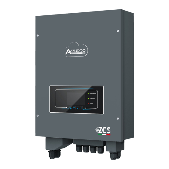
3000SP Storage inverter
Zucchetti Centro Sistemi S.p.A. - Green Innovation Division
Via Lungarno, 248 - 52028 Terranuova Bracciolini - Arezzo, Italy
tel. +39 055 91971 - fax. +39 055 9197515
innovation@zcscompany.com - zcs@pec.it – www.zcsazzurro.com
Reg. Pile IT12110P00002965 - Share Capital € 100,000.00 fully paid up
AR Company Reg. no. 03225010481 - REA AR no. 94189
ISO 9001 Certified Company - Certificate no. 9151 - CNS0 - IT-17778
User Manual
Advertisement
Table of Contents
Troubleshooting

Related Manuals for ZUCCHETTI AZZURRO 3000SP


Summary of Contents for ZUCCHETTI AZZURRO 3000SP
- Page 1 3000SP Storage inverter User Manual Zucchetti Centro Sistemi S.p.A. - Green Innovation Division Via Lungarno, 248 - 52028 Terranuova Bracciolini - Arezzo, Italy tel. +39 055 91971 - fax. +39 055 9197515 innovation@zcscompany.com - zcs@pec.it – www.zcsazzurro.com Reg. Pile IT12110P00002965 - Share Capital € 100,000.00 fully paid up AR Company Reg.
-
Page 2: Table Of Contents
Table of Contents Introduction ........................................7 Preliminary safety instructions ................................8 2.1. General safety instructions ..............................9 2.2. Instructions on battery installation and maintenance ....................9 2.3. Symbols on the inverter ............................... 10 Installation ........................................12 3.1. Product Overview ................................... 12 3.2. Contents of the packaging ..............................13 3.3. - Page 3 Operation ........................................38 6.1. Preliminary checks ................................38 6.2. Procedure for initial set-up ..............................38 6.3. “FREEZING” current sensors ............................. 41 6.4. Menu ......................................44 6.4.1. Settings ....................................45 6.4.2. Event List ..................................59 6.4.3. System Information ..............................60 6.4.4. Software Update ................................
- Page 4 12.1.1. Installation ....................................92 12.1.2. Configuration ................................... 93 12.1.3. Verification ..................................... 102 12.1.4. Troubleshooting ................................... 105 12.2. Ethernet adapter .................................. 110 12.2.1. Installation ..................................... 110 12.2.2. Verification ..................................... 112 12.2.3. Troubleshooting ................................... 114 12.3. 4G adapter ....................................115 12.3.1. Installation ..................................... 116 12.3.2.
- Page 5 Copyright statement Copyright of this manual belongs to Zucchetti Centro Sistemi S.p.A. No part of this manual (including the software, etc.) may be copied, reproduced or distributed in any form or by any means without the permission of Zucchetti Centro Sistemi S.p.A.
- Page 6 Preface General information Please read this manual carefully before installation, use or maintenance. This manual contains important safety instructions that must be followed during installation and maintenance of the system. Scope This manual describes the assembly, installation, electrical connection, commissioning, maintenance and troubleshooting of the ZCS 3000SP storage inverter.
-
Page 7: Introduction
1. Introduction The 3000SP storage inverter is an AC-connected bidirectional electrical energy inverter developed for photovoltaic production and domestic storage systems. The system can be combined with WeCo or Pylontech batteries offered in kit form by ZCS Azzurro. The system is also compatible with all existing photovoltaic inverters and modules and can be integrated into an existing system or installed together with a new photovoltaic system. -
Page 8: Preliminary Safety Instructions
For safety reasons, this inverter can only be installed by a qualified electrician with the necessary training and/or skills and knowledge. Zucchetti Centro Sistemi S.p.A. declines all responsibility for damage to property or personal injury caused by incorrect use of the device. -
Page 9: General Safety Instructions
If necessary, request assistance from an installer of photovoltaic systems or from Zucchetti Centro Sistemi SpA. Transport of the equipment, especially by road, must be carried out with vehicles suitable to protect the components (in particular, electronic components) against violent knocks, humidity, vibrations, etc. -
Page 10: Symbols On The Inverter
battery may damage it or cause it to catch fire. • To prevent voltage drops, the connection wires of the battery must be as short as possible, depending on the installation requirements. • Use a tester to check the battery voltage and the anode and cathode polarity before switching on the system. - Page 11 Beware of high voltage Beware of high temperatures Complies with the European Standards (CE) Ground connection point Read this manual before installing the inverter. Indication of the allowable temperature range Degree of protection of the equipment according to the IEC 70-1 standard (EN 60529 June 1997).
-
Page 12: Installation
3. Installation 3.1. Product Overview Each 3000SP inverter has been rigorously inspected prior to packaging and delivery. Do not flip over, shake or jerk the packaging during transport. Before opening the box, please check that the packaging of the product is intact and has not been damaged or tampered with. -
Page 13: Contents Of The Packaging
Figure 2 – Views of the 3000SP storage inverter and mounting bracket 3.2. Contents of the packaging Carefully check the contents of the packaging before installation, making sure that no element inside the packaging is missing or damaged. The package should contain the following components: 8 expansion plugs and 1 Storage inverter 1 mounting bracket... -
Page 14: Installation Environment
1 Pylontech battery 2 current transformers 2 CT terminals communication cable 1 Warranty Registration 2 warranty certificate 1 user manual Figure 3 - Components and accessories inside in the packaging 3.3. Installation environment For correct functioning of the system, the inverter and batteries must be installed in an environment with the following characteristics: •... -
Page 15: Installation Tools
3.4. Installation tools The following tools are required for installation of the inverter and batteries. Therefore, they must be prepared before installation. Tool Function Drill To drill holes in the wall for fixing the bracket Recommended drill bit: 6mm To screw and unscrew screws for Screwdriver the various connections Wire stripper... -
Page 16: Wall Installation Position
ESD gloves Protective clothing Safety goggles Protective clothing Protection mask Protective clothing Figure 4 – Tools required for installing the 3000SP inverter and batteries 3.5. Wall installation position The 3000SP storage inverter must be installed vertically on the wall (to ensure rapid and effective heat dissipation) or at an inclination not exceeding 15°. -
Page 17: Assembly Instructions
3.6. Assembly instructions 1) Correctly position the mounting bracket on the wall using a level to ensure that it is straight; mark the eight holes using a suitable marker pen. Drill the eight holes at the points marked on the wall using a 6 mm drill bit. 2) Insert the plugs horizontally into the holes, paying attention to the force and depth with which they are inserted. - Page 18 Figure 7 - Possibility of locking the inverter to the staff with a lock Note: For safety reasons, ZCS Spa and/or its partners may not carry out any technical repairs or maintenance work, or move the inverter or battery packs from and to the ground if they are installed at a height of more than 180 cm from the ground.
-
Page 19: Electrical Connections
4. Electrical connections • Carefully assess the risks deriving from electric shocks and chemical hazards! • Use a multi-metre to check the DC polarity of the battery and cables before connecting the power supply between the batteries and inverter. NOTE: an inverted polarity connection may cause irreparable damage to the inverter and batteries. Note: the Pylontech batteries, as well as the WeCo batteries do not require a disconnecting device for connecting to the storage inverter. -
Page 20: Connecting The Battery
4.1. Connecting the battery 1. Unscrew the 4 screws of the cover (A) with a star screwdriver (figure 10). 2. Remove the waterproof cover (B), loosen the cable gland (C), and then remove the stopper (G). 3. Route the battery cables (F) through the cable gland, then connect them using the OT terminal (E) supplied;... -
Page 21: Connecting A Pylontech Battery
The batteries can be recharged from the excess photovoltaic production or by using the forced charge mode indicated in the “% charge mode” section of this manual. 4.2. Connecting a Pylontech battery 4.2.1. Connecting a single battery This cable must be connected to the battery by inserting the RJ45 (8 pin) plug into the appropriate connection: 1. -
Page 22: Connecting Multiple Batteries In Parallel
Figure 12 - Connecting the communication cable to the Pylontech battery 4.2.2. Connecting multiple batteries in parallel If multiple batteries are present, check the parallel connections between one battery and another. a. In the case of Pylontech batteries, connect one of the two power cables (e.g. the positive, orange one) to the master battery, inserting the fast contact into the appropriate terminal;... - Page 23 Figure 11 – Connecting three Pylontech batteries in parallel The communication cables must be connected starting from the master battery and inserting the short jumper (supplied with the battery) or a jumper with a length of 0.6 m or 1.5 m (available on request, codes ZST-CABLE-0.6M and ZST-CABLE-1.5M) in the LINK connection PORT;...
-
Page 24: Connecting A Weco Battery
Figure 14 - Connecting the communication cable between three Pylontech batteries NOTE: the position of the DIP switches (white on a red background, as shown in the figure below) should not be changed. If it is changed by accident, contact the ZCS Service Centre at the toll-free number 800 72 74 64 (available on in Italy) or open a ticket by going to the support section of our website: https://www.zcsazzurro.com/it/support. -
Page 25: Connecting Multiple Batteries In Parallel
b. Make sure that the DIP switches are set as shown in the figure. Connect the ground cable to the battery through the threaded hole. NOTE : To connect the WECO batteries, use the blue or grey communication cable contained in the battery kit. - Page 26 Figure 17 – Communication cable between the batteries e. In case of additional batteries, the communication cable will be connected as indicated above for the connection of the MASTER battery to SLAVE 1. The last battery will only have the RS485-A port connected. Figure 18 –...
- Page 27 Figure 20 – Parallel connection of four WeCo batteries Figure 21 – Parallel connection of five WeCo batteries 27 / 121 User Manual 3000SP Rev. 1.1 16/03/2021 Identification: MD-AL-GI-00 Rev. 1.1 of 16/03/2021 - Application: GID...
-
Page 28: Ct / Battery Communication / Rs485 Connections
4.4. CT / Battery Communication / RS485 Connections Figure 22 – Wiring diagram of the 3000SP storage inverter in a system powered by renewable energy 28 / 121 User Manual 3000SP Rev. 1.1 16/03/2021 Identification: MD-AL-GI-00 Rev. 1.1 of 16/03/2021 - Application: GID... - Page 29 1) Correctly position the two current sensors (CT): - the CTa for measuring the energy exchanged with the grid must be positioned at the output of the exchange meter (utility side) and must include all the phase cables entering or leaving the meter. The CTa will therefore measure the energy taken from and fed into the grid by the photovoltaic system.
- Page 30 Figure 24 – Connecting the CT cables for the current sensors 3) Unscrew the 4 screws (A) of the central cover with a star screwdriver (figure 24). 4) Remove the waterproof cover (B), loosen the cable gland (C), and then remove the stopper (G). 5) Route the CT cable through the cable gland to the right of the cover, connect the cable to the CT terminal supplied, then insert the CT terminals into the corresponding ports (CTa for the exchange sensor and CTpv for the production sensor).
- Page 31 Communication cable between the battery and the 3000SP CAN communication inverter 3000SP CAN port CANHpin1 CANLpin2 GNDpin3 WeCo CAN port CANHpin1 CANLpin2 GNDpin3 Figure 12 – End of WeCo communication cable with inverter-side terminal in the CAN input Communication cable between the battery and the 3000SP CAN communication inverter 3000SP...
- Page 32 PYLONTECH CAN port CANHpin4 CANLpin5 485Apin1 & pin8 RS485 port 485Apin2 & pin7 Figure 26 – End of Pylontech communication cable with inverter-side terminal in the CAN input 7) Replace the waterproof cover and secure it with the 4 screws; tighten the cable gland. 8) Below are some simplified diagrams showing the correct and incorrect installation of the current sensors.
-
Page 33: Connecting To The Grid
Figure 28 – Incorrect positioning of the current sensors (CTa reading of the utilities only) In case of multiple phase cables connected in parallel directly under the import/export meter, make sure all the phase cables pass through the CTa sensor, as shown in the figure. Figure 29 –... -
Page 34: Connecting The Critical Load (Eps Function)
1) Unscrew the 4 screws (A) of the right cover with a star screwdriver (figure 30). 2) Remove the waterproof cover (B), loosen the cable gland (C), and then remove the stopper (G). 3) Route the AC cable (phase, neutral and ground) through the GRID cable gland, then connect the three cables to the corresponding terminal boards of the GRID terminal (Conventionally: BROWN - L, BLUE - N, YELLOW / GREEN - PE). - Page 35 appliances). Do not connect all the domestic utilities to the LOAD output, as this would compromise duration and operation of the EPS mode; in particular, certain loads, such as the electric motors of some pumps, may require inrush currents much higher than those tolerated by the inverter, causing a power failure. The EPS function requires an AC power meter (2NC + 2NA double-switchover contactor) to be installed in the system, which is not included in the kit of the storage inverter, and can be purchased separately from a retailer that sells electrical equipment.
-
Page 36: Buttons And Indicator Lights
5. Buttons and indicator lights Figure 16 – Buttons and indicator lights of the 3000SP inverter 5.1. Buttons • Press “Menu/Back” to enter the previous screen or main menu. • Press “Up” for the upper menu option or to increase the value by 1. •... -
Page 37: Operating Status
When the system is in alarm state (temporary or permanent) the red LED is steady. It is necessary to check the list of current events. 5.3. Operating status Green discharging Green charging Operating status Red alarm light light light Discharge Steady Discharging control Intermittent... -
Page 38: Operation
6. Operation 6.1. Preliminary checks Please carry out the following checks before commissioning the inverter. 1) The 3000SP inverter must be securely attached to the wall mounting bracket. 2) The polarity of the battery cables must be correct and the power cables must be connected securely. 3) THE GRID/LOAD cables must be connected securely and correctly to the corresponding terminal block. - Page 39 3. Start the 3000 SP storage inverter Supply DC power to the inverter by correctly switching on the batteries: In the case of Pylontech batteries, set the POWER switch of the battery, or (in the case of multiple units) of all the batteries, to I (ON position), then press the red SW button of the master battery for about one second;...
- Page 40 Figure 37 – Example of AC switch protecting the inverter b) After carrying out these operations, the display of the inverter will come on. At the time of start-up, the 3000SP inverter requires the following parameters be set: 1) Date and time 8)*Min.
-
Page 41: Freezing" Current Sensors
Code Country Code Country Code Country Germany VDE AR-N4105 Poland Cyprus CEI 0-21 Internal Germany BDEW India Australia Germany VDE 0126 Philippines Spain RD1699 Italy CEI 0-16 New Zealand Turkey UK-G83 America Denmark Greece - islands Slovakia VSD Greece - mainland EU EN 50438 Slovakia SSE Netherlands... - Page 42 1.Settings 14. CT Direction Figure 38 - Settings Menu To do this, once the inverter has been started, follow the steps below: 1. Press the ESC/Menu key (first key from the left) to enter the main menu. 2. Use the Enter key (fourth key from the left) to enter the “1. Settings” submenu and scroll down with the arrow until the “CT Direction”...
- Page 43 Power read by CTa Direction of power flow: IMPORT → from grid to utility EXPORT → from utility to grid Phase shift between the voltage and current of the phase where the CT is positioned Indicates the status of the current sensors: ...
-
Page 44: Menu
5. Exit the menu with the ESC/MENU key to return to the main interface. The initial start-up procedure is now complete and does not have to be repeated when the machine is restarted in the future. 6. At this point, the photovoltaic system can be switched on for production. Figure 40 –... -
Page 45: Settings
6.4.1. Settings 1.Settings 1.Battery Parameters 9.EPS Mode 2.Delete Energy Data 10.Logic interface control 3.Clear events 11.Autotest 4.Set Country 12.Working Mode 5.Commun.Address 13.CTpv Scale Factor Select. 6.Enable Country 14. CT Direction Change 7.Lingua 13.Set parameters Safety 8.Date and time 1. Battery parameters 1.Battery Parameters 1.Battery Type... - Page 46 display will show “Enter PWD!”, press OK to enter the password (use “Up” and “Down” to choose the number and “OK” to move to the next digit): - for standard settings, enter “0001” - for advanced settings (recommended for installers), enter ”0715” If the display shows “Incorrect, try again!”...
- Page 47 drops to 20%. Maximum charge current (A) Select “4. Maximum charge current (A)” and press “OK” to enter the menu for setting the maximum charge current. Press the “Up” and “Down” keys to change the value of the maximum charge current. Press “OK”...
- Page 48 Minimum discharge voltage Select “9. Min Discharge Voltage (V)” and press “OK” to enter the menu for setting the minimum discharge voltage. Press the “Up” and “Down” keys to change the value of the minimum discharge voltage. Press “OK” to move to the next digit and then confirm the setting; wait for “OK” to appear on the display.
- Page 49 3. Clear Events Select “3. Clear Events” and press the “OK” key twice to completely clear the events recorded; this will clear all the errors recorded in the memory of the inverter. Wait for “OK” to appear on the display, then press the “Menu/Back”...
- Page 50 A faster way to change the menu language is to press the “Menu/Back” key and “OK” key at the same time. In firmware version V1.90, the languages available are Chinese, English, Italian, French, German, Slovak and Ukrainian; future firmware updates may add new languages. 8.
- Page 51 When the correct password has been entered, the menu for setting the DRMs0 Control will appear. Select “1. Enable DRMs0” or “2. Disable DRMs0” if you want to enable or disable this function. Press “OK” and wait for “OK” to appear on the display. Note: this setting is only used in countries where the Australian standards are in force;...
- Page 52 ↓ Wait Testing 27.S1... ↓ Wait Test 27.S1 OK! ↓ Wait Testing 27.S2... ↓ Wait Test 27.S2 OK! ↓ Wait Testing 81>S1... ↓ Wait Test 81>S1 OK! ↓ Wait Testing 81>S2… ↓ Wait Test 81>S2 OK! ↓ Wait Testing 81<S1... ↓...
- Page 53 59.S1: 228V 902ms ↓ Press “down” 59.S2 264.5V 200ms ↓ Press “down” 59.S2: 229V 204ms ↓ Press “down” 27.S1 195.5V 400ms ↓ Press “down” 27.S1: 228V 408ms ↓ Press “down” 27.S2 92V 200ms ↓ Press “down” 27.S2: 227V 205ms ↓ Press “down”...
- Page 54 STD Self-test Select “2. STD Self-test” and press “OK” to start the standard self-test. The test procedure is the same as the fast self-test with the difference that the waiting times are longer (about 45 minutes) due to the 300-second wait between one test and the next. Set PF time Select “3.
- Page 55 This function enables the restrictive frequency thresholds required in some cases by local regulations. 12. Working mode Select “12. Working Mode” and press “OK” to enter the interface for setting the working mode. 12.Working Mode 1.Set Auto Mode 2.Set %Charge Mode 3.Set Hourly Mode 4.Set Passive Mode Set Auto Mode...
- Page 56 When the energy from the photovoltaic system is once When the battery is fully charged (or when the again lower than that requested by the loads, the charging power is limited), the excess energy will be system will give priority to the energy stored in the exported to the grid.
- Page 57 Battery (V) Indicates the voltage of the battery pack expressed in Volts Charge current Indicates the current at which the battery pack is currently being charged Discharge Indicates the current at which the battery pack is currently being current discharged Charge level Indicates the charge percentage of the battery pack Indicates the number of complete charging and discharging cycles...
- Page 58 Start of charge 22 h 00 m End of charge 05 h 00 m Charge Power 2000 W Start of Discharge 14 h 00 m End of Discharge 16 h 00 m Discharge Power 2500 W Set Passive Mode Select “4. Set Passive Mode”, then press “OK”. For more detailed information, ask Technical Support for a copy of the communication protocol in passive mode.
-
Page 59: Event List
6.4.2. Event List 2. Event list 1. List of current events 2. List of historical events To access the list of events, which contains information on the inverter errors, it is necessary to go back to the main interface and press the “Menu/Back” key, scroll down with the arrow to point “2. Event List” and enter with the “OK”... -
Page 60: System Information
6.4.3. System Information To enter the screen containing general information on the system, go back to the main menu and press the “Menu/Back” key, scroll down with the arrow to item “3. System Info” and enter with the “OK” key. You will then be able to enter the menu with information on the inverter and batteries. -
Page 61: Software Update
Max. charge threshold (V) Value of maximum voltage (charge) Max. discharge current Maximum discharge current in A Min. discharge voltage (V) Minimum voltage value (protection) Battery parameters Min. voltage threshold Minimum voltage value (discharge) End-of-discharge V Voltage with batteries charged to 0% Voltage with batteries charged to End-of-charge V 100%... - Page 62 6. Insert the SD card in the appropriate slot of the inverter. 7. If Pylontech batteries have been installed, start the system by first positioning the switches of all the batteries on “I” and then pressing the red SW button on the master battery (i.e. the battery connected to the storage system via the communication cable).
-
Page 63: Energy Statistics (Energy Statistic)
values. Once completed, Save. 19. The update procedure is now completed and the system must now be restarted correctly by following the initial start-up procedure described in the relevant section. Note: if the message “DSP1 Update Failed” or “DSP2 Updated Failed” appear during the update, the firmware update has not been successful. -
Page 64: Connections In Three-Phase Mode
7. Connections in three-phase mode The 3000SP storage inverter is a single-phase inverter, but it can be installed on a three-phase system by feeding and withdrawing power on a single-phase, with the aim of zeroing the vector sum of the powers of each phase ready by the import/export meter. - Page 65 According to this logic, the energy vector exchanges with the grid are cancelled and the 9 kW requested by the utility are met in part by the photovoltaic production and in part by the batteries. This configuration can be used when the installer deems it appropriate that the system manages the energy storage according to a global logic of a three-phase system, which takes into account the production and consumption on all phases.
-
Page 66: Ct / Battery Communication / Rs485 Connections
7.1. CT / Battery Communication / RS485 Connections Figure 43 – Wiring diagram of the 3000SP storage inverter inside a system powered by renewable energy 9) Correctly position the four current sensors (CT): - the CTa for measuring the energy exchanged with the grid must be positioned at the output of the exchange meter (utility side) on the same phase where the storage unit has been installed, and must include all the phase cables entering or leaving the meter. - Page 67 Figure 44 - Diagram of CTpv sensor connection 1) If it is necessary to extend the sensor connection cables, use UTP network cables. If there is electric/electronic noise near the cable that may cause interference, use FTP network cables. The cable can be extended by up to 100 metres with a minimum loss of signal.
- Page 68 Figure 46 – Connecting the CT cables for the current sensors 2) Unscrew the 4 screws (A) of the central cover with a star screwdriver (Figure 46). 3) Remove the waterproof cover (B), loosen the cable gland (C), and then remove the stopper (G). 4) Route the CT cable through the cable gland to the right of the cover, connect the cable to the CT terminal supplied, then insert the CT terminals into the corresponding ports (CTa for CTb and CTc for the exchange measurement sensors and CTpv for the production sensor).
-
Page 69: Operation
Figure 47 – Correct positioning of the current sensors Figure 48 – Incorrect positioning of the current sensors 7.2. Operation 7.2.1. Preliminary checks Please carry out the following checks before commissioning the inverter. 1) The 3000SP inverter must be securely attached to the wall mounting bracket. 2) The polarity of the battery cables must be correct and the power cables must be connected securely. -
Page 70: First Start-Up Of The Inverter
3) THE GRID/LOAD cables must be connected securely and correctly to the corresponding terminal block. 4) The AC switch must be connected correctly between the inverter’s GRID port and the grid. The automatic AC switch must be set to OFF. 5) In the case of connection to the EPS, make sure that the AC power contactor is connected correctly. - Page 71 4. Start the 3000 SP storage inverter Supply DC power to the inverter by correctly switching on the batteries: In the case of Pylontech batteries, set the POWER switch of the battery, or (in the case of multiple units) of all the batteries, to I (ON position), then press the red SW button of the master battery for about one second;...
-
Page 72: Freezing" Current Sensors
Figure 52 – Example of AC switch protecting the inverter 7.2.3. “FREEZING” current sensors Starting from firmware version 1.94, the “CT Direction” function is available on the display, which allows faster and more correct installation and configuration of the current sensors. This can be done once the inverter has been started by following these steps: 7. - Page 73 Figure 53 – Screen relating to the CT Direction submenu For each of the three sensors installed, the three lines show the reading of the power measured, the direction of this power and the Power Factor; for example, the figure shows a CTa sensor reading equal to 1.85 kW being imported from the grid towards the utility;...
- Page 74 Therefore, it will only be necessary to invert the probes with low PV, or equivalently the terminals inserted in the inverter's terminal block until the Power Factor value takes on the correct values (shown in figure 6). If it is not possible to obtain the required conditions, contact the ZCS Service Centre on the toll-free number 800 72 74 64 (only available in Italy) or open a ticket by going to the support section of our website at https://www.zcsazzurro.com/it/support.
-
Page 75: Setting Ctpv In Three-Phase Mode
7.2.4. Setting CTpv in three-phase mode 1.Settings 13.CTpv Scale Factor Table 4 – Settings Menu 1. Press the ESC/Menu key (first key from the left) to enter the main menu. 2. Use the Enter key (fourth from the left) to enter the “1. Settings” submenu and scroll down with the arrow until the “CTpv Scale Factor”... - Page 76 Figure 56 – Switching on the photovoltaic inverter 76 / 121 User Manual 3000SP Rev. 1.1 16/03/2021 Identification: MD-AL-GI-00 Rev. 1.1 of 16/03/2021 - Application: GID...
-
Page 77: Verification Of Proper Functioning
8. Verification of proper functioning To check the proper functioning of the inverter, follow these steps: Switch of all photovoltaic generation sources. 2. Lower the circuit breaker switch dedicated to protecting the 3000SP, the inverter will remain switched on but will go into error due to no alternating power. Power up the 3000SP by pulling on the AC switch. - Page 78 After pulling up the AC switch, the countdown will start according to the country code set (for CEI021-Internal, it will be 300s) to reconnect to the grid. During this period, check that the household loads are only powered by the grid and that there are no other power flows from either the photovoltaic system or the battery.
-
Page 79: Checking The Settings
7. Once the photovoltaic system has been activated, check that: a. The value of consumption shown on the screen remains constant as the photovoltaic power increases. b. Depending on the photovoltaic production, the system will operate according to the system's working mode. c. - Page 80 EPS Mode: (Enabled/Disabled). Working mode: in order to minimise exchanges with the grid, the correct mode will be “Automatic Mode.” DRMs0 Control (or Logical Interface): must be disabled. CTpv Scale Factor: 1.00 → Single-phase configuration 3.00 → Three-phase configuration CT Direction check the blocking status of the CTs. Battery type: check if the battery model on the display is consistent with the batteries installed.
- Page 81 81 / 121 User Manual 3000SP Rev. 1.1 16/03/2021 Identification: MD-AL-GI-00 Rev. 1.1 of 16/03/2021 - Application: GID...
-
Page 82: Technical Specifications
9. Technical specifications TECHNICAL DATA 3000SP 82 / 121 User Manual 3000SP Rev. 1.1 16/03/2021 Identification: MD-AL-GI-00 Rev. 1.1 of 16/03/2021 - Application: GID... -
Page 83: Troubleshooting And Maintenance
10. Troubleshooting and maintenance 10.1. Troubleshooting This section contains information and procedures on how to troubleshoot any faults and errors that may occur during operation of the 3000SP storage inverter. If you have any problems with the inverter, please follow these steps. Is the inverter located in a clean, dry and properly ventilated place? Is the battery switched ON? Are the cables correctly sized and as short as possible? - Page 84 If the alarm is sporadic and not consistent, check the Battery voltage is battery overvoltage setting and compare it with the ID05 BatOVP too high datasheet of the battery. If the setting is correct and the alarm persists, contact Technical Support. Vlvrtlow LVRT function error ID06...
- Page 85 HwADFaul Sampling error of ID17 tIGrid the grid current HwADFaul ID18 DCI sampling error tDCI HwADFaul Sampling error of ID19 tVGrid the grid voltage GFCIDevic GFCI sampling error. ID20 eFault MChip_Fau ID21 Microprocessor fault Error on the HwAuxPo ID22 auxiliary supply werFault voltage LLCBusOV...
- Page 86 and check if the error is still present. If the error Grid frequency persists, contact Technical Support. measurements Consistent between the main ID50 Fault_FGri DSP and the secondary DSP are not aligned DCI measurements between the main Consistent ID51 DSP and the Fault_DCI secondary DSP are not aligned...
- Page 87 unrecover Grid current is too ID70 OCPInstan high. Unrecoverable hardware fault unrecover ID75 EEPROM_ Unreadable EEPROM unrecover ID76 EEPROM_ Unreadable EEPROM unrecover Permanent fault on ID77 RelayFail relays Check that the 3000SP inverter is installed in a place without direct sunlight / other heat sources. Over Internal temperature ID81...
-
Page 88: Maintenance
Extract the SD card and clean it with a dry cloth. ID98 SDfault SD card error If the error persists, replace the SD card with a new one. ID99 Wi-Fi fault The Wi-Fi is in error Contact Technical Support Overcurrent ID100 BatOCD protection of battery... - Page 89 Cleaning the heatsink Use an air compressor, a soft dry cloth or soft-bristled brush to clean the heatsink. Do not use water, corrosive chemical substances or aggressive detergents to clean the heatsink. Disconnect the AC and DC power to the inverter before performing any cleaning operations. 89 / 121 User Manual 3000SP Rev.
-
Page 90: Uninstalling
11.4. Disposal Zucchetti Centro Sistemi S.p.a. is not liable for the disposal of the equipment, or parts thereof, that does not take place according to the regulations and standards in force in the country of installation. The symbol of the crossed-out wheeled bin indicates that the equipment, at the end of its useful life, must be disposed of separately from household waste. - Page 91 With your cooperation in the correct disposal of this product, you contribute to the reuse, recycling and recovery of the product, and to the protection of our environment. 91 / 121 User Manual 3000SP Rev. 1.1 16/03/2021 Identification: MD-AL-GI-00 Rev. 1.1 of 16/03/2021 - Application: GID...
-
Page 92: Monitoring Systems
12. Monitoring systems 12.1. External Wi-Fi adapter 12.1.1. Installation Unlike the internal Wi-Fi card, the external adapter must be installed for all compatible inverters. However, the procedure is quicker and easier as there is no need to open the front cover of the inverter. In order to monitor the inverter, the RS485 communication address must be set to 01 directly from the display. -
Page 93: Configuration
3) Connect the Wi-Fi adapter to the appropriate port, making sure to follow the direction of the connection and ensure correct contact between the two parts. Figure 58 – Inserting and securing the external Wi-Fi adapter 4) Switch on the inverter by following the procedure described in the manual. 12.1.2. - Page 94 If the Wi-Fi signal is present at the location where the inverter is installed, the configuration procedure can begin. If the Wi-Fi signal does not reach the inverter, a system must be installed to amplify the signal and bring it to the installation location.
- Page 95 Figure 60 – Disabling automatic reconnection to a network 2) Connect to a Wi-Fi network generated by the inverter's Wi-Fi adapter (i.e. AP_*******, where ******* indicates the serial number of the Wi-Fi adapter shown on the label of the device), which operates as an access point.
- Page 96 Figure 62 – Password of external Wi-Fi adapter Note: To ensure that the adapter is connected to the PC or smartphone during the configuration procedure, enable automatic reconnection of the AP_******* network. Figure 63 – Password entry prompt 96 / 121 User Manual 3000SP Rev.
- Page 97 Note: the Access Point is not able to provide internet access; confirm to maintain the Wi-Fi connection, even if the internet is not available Figure 64 – Screen indicating that the Internet cannot be accessed 4) Open a browser (Google Chrome, Safari, Firefox) and enter the IP address 10.10.100.254 in the address bar at the top of the screen.
- Page 98 5) The status screen will open, showing the logger information such as the serial number and firmware version. Check that the Inverter Information fields are filled in with the inverter information. The language of the page can be changed using the command in the top right-hand corner. Figure 66 –...
- Page 99 Note: check that the signal strength is greater than 30%, if not, bring the router closer or install a repeater or signal amplifier. Click Next. Figure 67 – Screen for selecting the available wireless network (1) 8) Enter the password of the Wi-Fi network (Wi-Fi modem), clicking on Show Password to make sure it is correct;...
- Page 100 Figure 68 – Screen for entering the password of the wireless network (2) 9) Click “Next” again without ticking any of the options relating to the system security. Figure 69 - Screen for setting the security options (3) 100 / 121 User Manual 3000SP Rev.
- Page 101 10) Click “OK”. Figure 70 – Final configuration screen (4) 11) At this point, if the configuration of the adapter is successful, the last configuration screen will appear, and the telephone or PC will unpair from the inverter’s Wi-Fi network. 12) Manually close the web page with the Close key on the PC por remove it from the background of the telephone.
-
Page 102: Verification
Figure 71 - Successful configuration screen 12.1.3. Verification Wait two minutes after configuring the adapter and then go back to the Wi-Fi network selection screen to verify that the AP_******* network is no longer present. The absence of the Wi-Fi network in the list will confirm the successful configuration of the Wi-Fi adapter. - Page 103 If the Wi-Fi network is still present in the list, connect to it again and enter the status page. Check the following information: a. Wireless STA mode i. Router SSID > Router name ii. Signal Quality > other than 0% iii.
- Page 104 Figure 74 - Initial status of LEDs 2) Final status: NET (left LED): steady on COM (central LED): steady on READY (right LED): flashing on Figure 75 - Final status of LEDs If the NET LED does not light up or if the Remote Server A option in the Status page still shows “Not Connected”, the configuration was not successful, i.e.
-
Page 105: Troubleshooting
It is necessary to reset the adapter: Press the Reset button for 10 seconds and release After a few seconds, the LEDs will turn off and READY will start to flash quickly The adapter has now returned to its initial state. At this point, the configuration procedure can be repeated again. - Page 106 Figure 77 - Irregular communication status between inverter and Wi-Fi Check the Modbus address set on the inverter: Enter the main menu with the ESC key (first key on the left), go to System Info and press ENTER to enter the submenu. Scroll down to the Modbus address parameter and make sure it is set to 01 (and in any case, other than 00).
- Page 107 2) Irregular communication with remote server NET (left LED ): off COM (central LED): on READY (right LED): flashing on Figure 79 - Irregular communication status between Wi-Fi and remote server Check that the configuration procedure has been carried out correctly and that the correct network password has been entered.
- Page 108 Using an Android mobile phone as a modem a) Check that the 3G/LTE connection is active on your smartphone. Go to the Settings menu of the the phone), operating system (the gear icon on the screen with a list of all the apps installed on select “Other”...
- Page 109 Figure 81 - Configuration of an iOS smartphone as a hotspot router At this point, it is necessary to re-configure the Wi-Fi adapter using a PC or smartphone other than the one used as a modem. During this procedure, when asked to select the Wi-Fi network, choose the one activated by the smartphone and then enter the password associated with it (which can be changed from the personal hotspot settings).
-
Page 110: Ethernet Adapter
12.2. Ethernet adapter 12.2.1. Installation Installation must be carried out for all inverters compatible with the adapter. However, the procedure is quicker easier there need open front cover inverter. Proper operation of the device requires the presence of a modem correctly connected to the network and in operation in order to achieve stable data transmission from the inverter to the server. - Page 111 3) Remove the ring nut and the waterproof cable gland from the adapter to allow the network cable to pass through; then insert the network cable network into the appropriate port on the inside of the adapter and tighten the ring nut and cable gland to ensure a stable connection. Figure 83 –...
-
Page 112: Verification
5) Connect the other end of the network cable to the ETH output (or equivalent) of the modem or a suitable data transmission device. Figure 85 – Connecting the network cable to the modem 6) Switch on the inverter by following the procedure described in the manual. 7) Unlike Wi-Fi cards, the Ethernet adapter does not need to be configured and starts transmitting data shortly after the inverter is switched on. - Page 113 Figure 86 - Initial status of LEDs 2) Final status: NET (left LED): steady on COM (central LED): steady on SER (right LED): flashing on Figure 87 - Final status of LEDs 113 / 121 User Manual 3000SP Rev. 1.1 16/03/2021 Identification: MD-AL-GI-00 Rev.
-
Page 114: Troubleshooting
12.2.3. Troubleshooting Status of LEDs present on the adapter Irregular communication with inverter NET (left LED): steady on COM (central LED ): off SER (right LED): flashing on Figure 88 - Irregular communication status between the inverter and adapter Check the Modbus address set on the inverter: Enter the main menu with the ESC key (first key on the left), go to System Info and press ENTER to enter the submenu. -
Page 115: Adapter
Figure 89 - Irregular communication status between the adapter and remote server Check that the router has access to the network and that the connection is stable; check that a PC can access the Internet Check that port 80 of the router is open and enabled to send data. It is advisable to check the brand and model of the home router you are trying to connect to the Ethernet adapter;... -
Page 116: Installation
12.3.1. Installation Installation must be carried out for all inverters compatible with the adapter. However, the procedure is quicker and easier as there is no need to open the front cover of the inverter. Installation tools: Cross screwdriver 4G adapter 1) Switch off the inverter following the procedure described in this manual. - Page 117 3) Insert the 4G adapter into the appropriate port, making sure to follow the direction of the connection and ensure correct contact between the two parts. Secure the 4G adapter by tightening the two screws inside the package. Figure 91 – Inserting and securing the 4G adapter 4) Switch on the inverter by following the procedure described in the manual.
-
Page 118: Verification
12.3.2. Verification After installing the adapter, within the next 3 minutes check the status of the LEDs on the device to ensure that the device is configured correctly. Status of LEDs present on the adapter 1) Initial status: NET (left LED ): off COM (central LED): flashing on SER (right LED): flashing on Figure 92 - Initial status of LEDs... - Page 119 Figure 93 - Final status of LEDs Status of LEDs present on the adapter 1) Irregular communication with inverter NET (left LED): on COM (central LED ): off SER (right LED): on Figure 94 - Irregular communication status between inverter and adapter Check the Modbus address set on the inverter: Enter the main menu with the ESC key (first key on the left), go to System Info and press ENTER to enter the submenu.
- Page 120 Check that the 4G adapter is correctly and securely connected to the inverter, making sure to tighten the two cross-head screws provided. 2) Irregular communication with remote server: NET (left LED): flashing on COM (central LED): on SER (right LED): flashing on Figure 95 - Irregular communication status between the adapter and remote server Check that the 4G signal is present in the installation location (the adapter uses the Vodafone network for 4G transmission;...
-
Page 121: Warranty Terms And Conditions
13. Warranty terms and conditions To view the “Warranty Terms and Conditions” offered by ZCS Azzurro, please refer to the documentation inside the product box and on the website www.zcsazzurro.com. 121 / 121 User Manual 3000SP Rev. 1.1 16/03/2021 Identification: MD-AL-GI-00 Rev.
Need help?
Do you have a question about the AZZURRO 3000SP and is the answer not in the manual?
Questions and answers