Table of Contents
Advertisement
Quick Links
Advertisement
Table of Contents
Troubleshooting

Subscribe to Our Youtube Channel
Related Manuals for ZUCCHETTI AZZURRO 1PH HYD3000-HYD6000-ZSS-HP


Summary of Contents for ZUCCHETTI AZZURRO 1PH HYD3000-HYD6000-ZSS-HP
- Page 2 Hybrid Inverter 1PH HYD3000-HYD6000-ZSS-HP User Manual 1/240 User Manual 1PH HYD3000-HYD6000-ZSS-HP Rev. 1.2 24/04/2023 Identification: MD-AL-GI-00 (System info) Rev. 1.1 of 07/03/2022 - Application: GID...
-
Page 3: Table Of Contents
Summary Introduction ......................................9 Preliminary safety instructions ..............................10 2.1. Safety Notes ....................................10 2.2. Assembly and maintenance diagram ..........................12 2.3. Symbols on the inverter ..............................13 Installation ......................................15 3.1. Product overview ................................... 15 3.2. Package contents ..................................16 3.3. - Page 4 4.9.3. WeCo 4k4 configuration ............................53 4.10. Connecting a WeCo 4k4 PRO battery ..........................54 4.10.1. Connecting a single 4k4 PRO battery ........................54 4.10.2. Connecting multiple batteries in parallel 4k4 PRO ..................56 4.10.3. WeCo 4k4 PRO configuration ..........................58 4.11.
- Page 5 5.1.1. Multifunction communication interface (COM) .................... 104 5.1.2. Measurement of exchange via the single-phase DDSU Meter ..............110 5.1.3. Measuring external production through the DDSU single-phase Meter ..........113 5.1.4. Setting up exchange meter and production DDSU single-phase Meter ..........116 5.1.5.
- Page 6 13. Monitoring system ..................................185 13.1. External Wi-Fi adapter..............................186 13.1.1. Installation ................................... 186 13.1.2. Configuration ................................187 13.1.3. Check ....................................196 13.1.4. Troubleshooting................................. 199 13.2. Ethernet adapter ................................. 203 13.2.1. Installation ................................... 203 13.2.2. Check ....................................205 13.2.3. Troubleshooting................................. 206 13.2.4.
- Page 7 6/240 User Manual 1PH HYD3000-HYD6000-ZSS-HP Rev. 1.2 24/04/2023 Identification: MD-AL-GI-00 (System info) Rev. 1.1 of 07/03/2022 - Application: GID...
- Page 8 The manual must always accompany the equipment, even when it is transferred to another user or plant. The copyright of this user manual belongs to Zucchetti Centro Sistemi S.p.A. No part of this manual (including Copyright statement the software, etc.) may be copied, reproduced or distributed in any form or by any means without the...
- Page 9 Preface General information Please read this manual carefully before proceeding with installation, operation or maintenance. This manual contains important safety precautions that must be followed and observed during the installation and maintenance of the equipment. This manual describes the assembly, installation, electrical connections, commissioning, maintenance and Scope troubleshooting of the 1PH HYD3000-HYD6000-ZSS-HP hybrid inverter.
-
Page 10: Introduction
Introduction The 1PH HYD3000-HYD6000-ZSS-HP hybrid inverter is used in photovoltaic systems with battery storage. The system can be combined with AZZURRO, WECO and PYLONTECH batteries supplied in kit form by ZCS Azzurro. The energy produced by the photovoltaic system will be optimised for maximum self-consumption. The 1PH HYD3000-HYD6000-ZSS-HP inverter can operate in automatic mode and in charge mode for the time of use and charge/discharge. -
Page 11: Preliminary Safety Instructions
Improper use may result in electric shock and injury, as well as damage to the equipment and its parts. Contact Zucchetti Centro Sistemi S.p.A. for any doubts or problems. DO NOT carry out repairs yourself, as this could cause injury or damage. - Page 12 • The 1PH HYD3000-HYD6000-ZSS-HP inverter can reach high temperatures and contains moving parties during operation. Switch off the 1PH HYD3000-HYD6000-ZSS-HP inverter and wait for it to cool down before performing any maintenance. • Keep children away from the batteries and from the 1PH HYD3000-HYD6000-ZSS-HP inverter. •...
-
Page 13: Assembly And Maintenance Diagram
2.2. Assembly and maintenance diagram The batteries must be protected against short circuits during transport and installation. The inverter 1PH HYD3000-HYD6000-ZSS-HP inverter and batteries must be placed in well-ventilated • areas. Do not positive the 1PH HYD3000-HYD6000-ZSS-HP inverter or batteries in a cabinet or in an airtight •... -
Page 14: Symbols On The Inverter
2.3. Some safety symbols are present on the inverter. Before installing the inverter, it is important to read and Symbols on the inverter understand the contents of the symbols. This symbol indicates a hazardous situation which, if not avoided, will result in injury. - Page 15 Positive polarity and negative polarity of the DC voltage (Photovoltaic and Battery). This side up. The 1PH HYD3000-HYD6000-ZSS-HP inverter must always be transported, handled and stored in such a way that the arrows are always pointing upwards. 14/240 User Manual 1PH HYD3000-HYD6000-ZSS-HP Rev.
-
Page 16: Installation
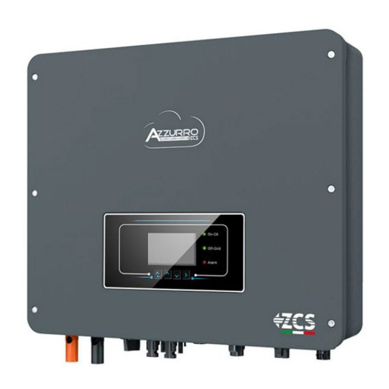
Installation 3.1. The 1PH HYD3000-HYD6000-ZSS-HP inverter is subjected to strict controls and inspection before packaging and Product overview delivery. Do not turn the 1PH HYD3000-HYD6000-ZSS-HP inverter upside down during delivery. Carefully check the packaging and accessories before installation. Caution Figure 2 - Diagram of a system on which an 1PH HYD3000-HYD6000-ZSS-HP hybrid inverter is installed Battery input terminals Connection port 1 DC switch... -
Page 17: Package Contents
3.2. Carefully inspect the packaging and accessories before installation. The package must contain the following Package contents accessories: 1 x rear panel 2 x PV+ input terminals 2 x PV- input terminals 1 x Inverter 2 x metal terminals fixed to 2 x metal terminals fixed to PV+ input 1 x BAT+ input terminal 1 x BAT- input terminal... -
Page 18: Installation Area
3.3. Installation area Choose a dry, clean and tidy place suitable for installation. Ambient temperature range: -25 ~ 60 °C. • Relative humidity: 0 ~ 100% (without condensation). • Install the 1PH HYD3000-HYD6000-ZSS-HP inverter in a well-ventilated area. • Do not place flammable or explosive materials near the 1PH HYD3000-HYD6000-ZSS-HP inverter. •... - Page 19 For tightening the screws to 4 mm Allen key connect the rear panel to the inverter Crimping tools For crimping the power cables For checking the ground connection Multi-meter Marker For marking Tape measure For measuring distances For making sure that the rear Spirit level panel is installed correctly ESD gloves...
-
Page 20: Wall Installation Position
3.5. Wall installation position The 1PH HYD3000-HYD6000-ZSS-HP inverter must be mounted vertically (to ensure rapid heat dissipation). Install the 1PH HYD3000-HYD6000-ZSS-HP inverter in a location protected from direct sunlight and possible snow accumulation. Ensure that the installation position is well ventilated. Figure 3 –... -
Page 21: Installation Instructions
Step 5: Use the grounding hole of the heat sink to ground the 1PH HYD3000-HYD6000-ZSS-HP inverter. Note: For safety reasons, Zucchetti Centro Sistemi Spa and/or its partners may not perform any technical repairs or maintenance or move the inverter or battery pack if they are installed at a height of more than 180 cm above... -
Page 22: Electric Connections
the ground. Inverters and/or battery packs installed at greater heights must be moved to the ground before they can be repaired or serviced. Figure 4 – Instructions for installing the storage inverter and battery pack Electric connections • Carefully assess the risks of electric shock and chemical hazards! •... - Page 23 The 1PH HYD3000-HYD6000-ZSS-HP inverter is intended for use in photovoltaic systems with battery storage. If not used as intended, the protection provided by the equipment may be impaired. The inverter must be installed and serviced by a professional electrician. Wear rubber gloves and protective clothing (safety goggles and boots) when working on high voltage/high current systems, such as inverters and battery systems.
- Page 24 Figure 5 – Electrical connections 23/240 User Manual 1PH HYD3000-HYD6000-ZSS-HP Rev. 1.2 24/04/2023 Identification: MD-AL-GI-00 (System info) Rev. 1.1 of 07/03/2022 - Application: GID...
-
Page 25: Wiring Instructions
4.1. Wiring instructions Recommended Recommended cable Component Description cable type specification + : Connect the positive electrode of Multi-core copper the lithium battery Cross-section area of the cable for outdoor conductor: 16~20 mm - : Connect the negative electrode of the lithium battery + : Connect the positive electrode of Common... -
Page 26: Connecting Pgnd Cables
4.2. Connecting PGND cables Connect the inverter to the grounding electrode using protective ground cables (PGND). The inverter does not include a transformer, the positive and negative polarities of the PV array DO NOT need to be grounded. Otherwise, it will cause the inverter to fail. All non- current-carrying metal parts (such as the PV module frame, PV rack, combiner box housing, inverter housing) in the PV power system must be grounded. -
Page 27: Connecting To Grid
Note 1: L3 is the length between the insulation layer of the ground cable and the crimped part. L4 is the distance between the crimped part and the conductor wires protruding from the crimped part. Note 2: The cavity formed after crimping the conductor crimp strip will completed envelop the wires. The wires must be in close contact with the terminal. - Page 28 Step 2: Pass the cable through the terminal. Step 3: According to the mark, lock the cable in the hole on the terminal and tighten it with the Allen key. Step 4: Push the terminal forward until a ‘click’ sound is heard. 27/240 User Manual 1PH HYD3000-HYD6000-ZSS-HP Rev.
- Page 29 Step 5: Connect the terminal to the inverter port and push the terminal forward until a ‘click’ is heard to indicate that the terminal is connected. Steps 1, 2 and 3 indicate the steps for connecting the connector to the AC terminal block. Steps 4, 5 and 6 indicate the steps for disconnecting the connector from the AC terminal block.
-
Page 30: Connecting A Critical Load (Eps Function)
4.4. Critical Load (LOAD): in the event of a power failure (or OFF-GRID operation), if the EPS function is enabled, Connecting a Critical Load (EPS function) the 1PH HYD3000-HYD6000-ZSS-HP inverter will operate in Emergency Power Supply (EPS) mode using the energy stored in the battery to supply power to the critical load via the LOAD connection port. - Page 31 Step 4: Insert the load connector until a “click” sound is heard, then tighten the retaining nut to the instant value, as shown in the figure below, to ensure the wire is securely connected. Step 5: Connect the connected load connector to the inverter's load connector. Turn the knob of the AC connector to lock it until a “click”...
- Page 32 Removing the load connector: Press and hold the button to unlock and turn the knob counter-clockwise to the unlocked position, then pull out the load connector. Make sure the grid is correctly disconnected before removing the load connector. A change-over switch must be inserted between the EPS output of the inverter and the critical loads. Change-over positions The change-over switch is necessary.
- Page 33 Note: If the system is equipped with a production metre, take into account that the energy for the critical load is drawn upstream of the meter, so this energy, even if produced by photovoltaic panels, is not counted as energy produced.
-
Page 34: Photovoltaic Connection
4.5. Photovoltaic connection Recommended specifications for DC input cables Range Recommended value Cross section (mm /AWG) Cable outer diameter (mm 4.0-6.0 / 11-9 4.0 / 11 4.5~7.8 Step 1: Prepare the positive and negative photovoltaic cables. Procedure: Figure 7 – Preparing the positive and negative PV cables Step 2: Insert the crimped positive and negative cables into the corresponding photovoltaic connectors. - Page 35 Figure 9 – Connecting the photovoltaic connectors Before removing the positive and negative connectors, make sure that the automatic DC circuit breaker is OPEN. Caution Use a MC4 wrench to disconnect the photovoltaic connectors. Removal procedure Figure 55 – Disconnecting the photovoltaic connectors Connect the 1PH HYD3000-HYD6000-ZSS-HP inverter to the photovoltaic strings using DC input power cables.
- Page 36 To configure the inverter channels correctly: 1. Press the first button on the left of the display: 2. Press the last arrow on the right (enter) to access the basic settings: 1. Basic settings 2. Advanced settings 3. Production statistics 4.
- Page 37 If the strings are different (e.g. installed on two separate pitches or consisting of a different number of panels), Independent mode (default): the input model must be set to “independent mode.” If the strings are connected in parallel, the input mode must be set to “parallel mode.” Parallel mode: Depending on the type of inverter, select the appropriate inverter accessories (cables, fuse holders, fuses, Note:...
-
Page 38: Battery Connection
4.6. Battery connection Figure 7 – Installing the battery connection 37/240 User Manual 1PH HYD3000-HYD6000-ZSS-HP Rev. 1.2 24/04/2023 Identification: MD-AL-GI-00 (System info) Rev. 1.1 of 07/03/2022 - Application: GID... -
Page 39: Connecting The Pylontech Us2000 Battery
If the storage capacity needs to be increased by adding one or more batteries to an existing system, ensure that NOTE all the batteries (present and to be installed) are fully charged. To check the charge status of each battery, connect them one at a time to the inverter and view the charge level on the display (all instant information can be accessed by pressing the “down”... - Page 40 Communication cable pinout between Pylontech battery and inverter, from left to right PIN 1: blue PIN 2: white-blue PIN 1: white orange PIN 2: orange PIN 3: white green PIN 4: blue PIN 5: white blue PIN 6: green PIN 7: white brown PIN 8: brown 2.
-
Page 41: Connecting Multiple Batteries In Parallel Pylontech Us2000
Figure 13- Connecting the power cable from the Pylontech battery to the inverter In the case of a single battery, two power cables (positive and negative) will then be connected to the positive and negative outputs of the inverter respectively, as shown in the figure. 4.7.2. -
Page 42: Pylontech Us2000 Configuration
As for the power connections, in the case of Pylontech batteries, connect one of the two power cables (e.g. the orange positive one) to the master battery, inserting the quick contact in the appropriate terminal. Then connect the other cable (e.g. the black negative one) to the last battery in the group, as shown in the figure below. - Page 43 5. Press the last arrow on the right (enter) to access the advanced settings (enter password 0715): 1. Basic settings 2. Advanced settings 3. Production statistics 4. System Info 5. Event list 6. SW Update 6. Now press the last arrow on the right to access the battery parameters 1.
-
Page 44: Pylontech Us5000 Battery Connection
4.8. Pylontech US5000 battery connection 4.8.1. Connecting a single Pylontech US5000 battery Inside the inverter box there is the cable for communication between the battery and inverter. This cable must be connected to the battery by inserting the RJ45 (8 pin) plug into the appropriate connection: 1. - Page 45 Communication cable pinout between Pylontech battery and inverter, from left to right PIN 1: blue PIN 2: white-blue PIN 1: white orange PIN 2: orange PIN 3: white green PIN 4: blue PIN 5: white blue PIN 6: green PIN 7: white brown PIN 8: brown 2.
-
Page 46: Connecting Multiple Batteries In Parallel Pylontech Us5000
Figure 18- Connecting the power cable from the Pylontech battery to the inverter In the case of a single battery, two power cables (positive and negative) will then be connected to the positive and negative outputs of the inverter respectively, as shown in the figure. 4.8.2. - Page 47 NOTE: the position of the DIP switches (white on a red background, as shown in the figure below) must all be in the down position (OFF) and must not be changed. If it is changed by accident, please contact the ZCS Service Centre at the toll-free number 800 72 74 64 (available only in Italy) or open a ticket by going to the “support”...
-
Page 48: Pylontech Us5000 Configuration
4.8.3. Pylontech US5000 configuration To correctly configure the battery parameters: 1. Press the first button on the left of the display: 2. Press the last arrow on the right (enter) to access the advanced settings (enter password 0715): 1. Basic settings 2. -
Page 49: Connecting A Weco 4K4 Battery
4. Check that the parameters are set correctly: 1.Battery type Pylon-AH US5000 4.Depth of Discharge 6.Save 4.9. Connecting a WeCo 4k4 battery 4.9.1. Connecting a single 4k4 battery Inside the battery box is the cable for communication between the battery and inverter. This cable must be connected to the battery by inserting the RJ45 (8 pin) plug into the appropriate Input: 1. - Page 50 a. Make sure that the DIP switches are set as shown in the figure. Figure 21 - Communication cable between the inverter and WeCo 4k4 battery b. Connect the ground cable to the battery through the threaded hole. NOTE: to connect the WeCo batteries, use the communication cable labelled WECO contained in the inverter kit (or otherwise use the one inside the battery kit, leaving the RJ45 side intact and cutting the other side to use orange and white-orange, connecting them to the COM port of the inverter).
-
Page 51: Connecting Multiple Batteries In Parallel 4K4
Figure 23- Connecting the power cable from the WeCo battery to the inverter In the case of a single battery, two power cables (positive and negative) will then be connected to the positive and negative outputs of the inverter respectively, as shown in the figure. 4.9.2. - Page 52 Figure 24 – Communication cable between WeCo 4k4 batteries e. In the case of additional batteries, the communication cable should be connected as shown above for connecting the master battery to slave 1 battery. The last battery will only have the RS485-A port connected. g.
- Page 53 Figure 26 – Connecting three WeCo 4k4 batteries in parallel Figure 27 – Connecting four WeCo 4k4 batteries in parallel Figure 28 – Connecting five WeCo 4k4 batteries in parallel 52/240 User Manual 1PH HYD3000-HYD6000-ZSS-HP Rev. 1.2 24/04/2023 Identification: MD-AL-GI-00 (System info) Rev.
-
Page 54: Weco 4K4 Configuration
4.9.3. WeCo 4k4 configuration To correctly configure the battery parameters: 1. Press the first button on the left of the display: 2. Press the last arrow on the right (enter) to access the advanced settings (enter password 0715): 1. Basic settings 2. -
Page 55: Connecting A Weco 4K4 Pro Battery
4. Check that the parameters are set correctly: 1.Battery type WeCo 4.Depth of Discharge 6.Save 4.10. Connecting a WeCo 4k4 PRO battery 4.10.1. Connecting a single 4k4 PRO battery Inside the battery box is the cable for communication between the battery and inverter. This cable must be connected to the battery by inserting the RJ45 (8 pin) plug into the appropriate Input: a. - Page 56 Figure 29 - Communication cable between the inverter and WeCo 4k4 PRO battery b. Make sure that the DIP switches are set as shown in the figure. c. Connect the ground cable to the battery through the threaded hole. NOTE: to connect the WeCo batteries, use the communication cable labelled WECO contained in the inverter kit (or otherwise use the one inside the battery kit, leaving the RJ45 side intact and cutting the other side to use orange and white-orange, connecting them to the COM port of the inverter).
-
Page 57: Connecting Multiple Batteries In Parallel 4K4 Pro
Figure 31- Connecting the power cable from the WeCo 4k4 PRO battery to the inverter In the case of a single battery, two power cables (positive and negative) will then be connected to the positive and negative outputs of the inverter respectively, as shown in the figure. 4.10.2. - Page 58 d. In the case of additional batteries, the communication cable should be connected as shown above for connecting the master battery to slave 1 battery. e. The last battery will only have the RS485-A port connected. As for the power connections, connect one of the two power cables (e.g. the red positive one) to the master battery, inserting the metal ring in the appropriate terminal.
-
Page 59: Weco 4K4 Pro Configuration
Figure 35 – Connecting four WeCo 4k4 PRO batteries in parallel Figure 36 – Connecting five WeCo 4k4 PRO batteries in parallel 4.10.3. WeCo 4k4 PRO configuration To correctly configure the battery parameters: 1. Press the first button on the left of the display: 58/240 User Manual 1PH HYD3000-HYD6000-ZSS-HP Rev. - Page 60 2. Press the last arrow on the right (enter) to access the advanced settings (enter password 0715): 1. Basic settings 2. Advanced settings 3. Production statistics 4. System Info 5. Event list 6. SW Update 3. Now press the last arrow on the right to access the battery parameters 1.
-
Page 61: Connecting A Weco 4K4-Lt Battery
4.11. Connecting a WeCo 4k4-LT battery 4.11.1. Connecting a single 4k4-LT battery Inside the battery box is the cable for communication between the battery and inverter. This cable must be connected to the battery by inserting the RJ45 (8 pin) plug into the appropriate Input: a. - Page 62 b. Make sure that the DIP switches are set as shown in the figure. c. Connect the ground cable to the battery through the threaded hole. NOTE: to connect the WeCo batteries, use the communication cable labelled WECO contained in the inverter kit (or otherwise use the one inside the battery kit, leaving the RJ45 side intact and cutting the other side to use orange and white-orange, connecting them to the COM port of the inverter).
-
Page 63: Connecting Multiple Batteries In Parallel 4K4-Lt
Figure 39- Connecting the power cable from the WeCo 4k4-LT battery to the inverter 4.11.2. Connecting multiple batteries in parallel 4k4-LT If there are multiple batteries: a. Check that the batteries have the same voltage level by switching them off, disconnecting them and switching them on one at a time, measuring the + and - terminals with a tester. - Page 64 Figure 40 – Communication cable between WeCo 4k4-LT batteries e. In the case of additional batteries, the communication cable should be connected as shown above for connecting the master battery to slave 1 battery. The last battery will only have the RS485-A port connected. g.
-
Page 65: Weco 4K4-Lt Configuration
Figure 42 – Connecting three WeCo 4k4-LT batteries in parallel Figure 43 – Connecting four WeCo 4k4-LT batteries in parallel Figure 44 – Connecting five WeCo 4k4-LT batteries in parallel 4.11.3. WeCo 4k4-LT configuration To correctly configure the battery parameters: 1. - Page 66 2. Press the last arrow on the right (enter) to access the advanced settings (enter password 0715): 1. Basic settings 2. Advanced settings 3. Production statistics 4. System Info 5. Event list 6. SW Update 3. Now press the last arrow on the right to access the battery parameters 1.
-
Page 67: Switching On Weco 4K4-Lt Batteries
1.Battery type WeCo 4.Depth of Discharge 6.Save 4.11.4. Switching on WeCo 4k4-LT batteries In order to carry out the correct switch-on procedure: 1. The batteries must all be switched off (side switch to 0); 2. Inverter DC rotary switch set to OFF; 3. -
Page 68: Weco 4K4-Lt Battery And Weco 4K4 Pro Batteries In Parallel
4.12. WeCo 4k4-LT battery and WeCo 4k4 PRO batteries in parallel For a new system, we do not recommend installing a mixed solution with WeCo 4k4PRO and WeCo 4k4-LT batteries. When using WeCo 4k4PRO and WeCo 4k4-LT batteries, the WeCo 4k4-LT batteries must be installed first and then the 4k4PRO batteries as shown in the figure. -
Page 69: Connecting A Weco 5K3 Battery
d. ….. e. Positive input (+) of slave N-1 battery (second-last) connected to positive input (+) of slave N battery (last). Negative input (-) of slave N-1 battery (second-last) connected to negative input (-) of slave N battery (last). g. Negative input (-) of slave N battery (second-last) connected to negative input (-) of inverter. NOTE: When switched on for the first time, the WeCo batteries receive a command from the inverter to start regular operation only when all of them have collectively reached a state of full charge (i.e. - Page 70 Figure 46 - Communication cable between the inverter and WeCo 5k3 battery Make sure that the DIP switches are set as shown in the figure. Connect the ground cable to the battery through the threaded hole. Note: Switch off the batteries each time the position of the DIP switches is changed. To access the battery connection, remove the cover of the LV section located on the left side by unscrewing the screws with a cross screwdriver.
- Page 71 Low Voltage High Voltage (HV) (LV) connection connection Attention: When connecting 5k3 batteries to single-phase hybrid inverters, only use the low voltage section. To avoid damage to batteries or inverters, do not use the high voltage section. In case of a single battery: 1.
-
Page 72: Connecting Multiple Batteries In Parallel 5K3
Figure 47 – Connecting the WeCo 5k3 battery 4.13.2. Connecting multiple batteries in parallel 5K3 If there are multiple batteries: a. Check that the batteries have the same voltage level by switching them off, disconnecting them and switching them on one at a time, measuring the + and - terminals with a tester. Make sure that the difference between the voltages of all the batteries is less than 2 Volt. - Page 73 c. From the master battery, connect the communication cable from the RS485-B port to the RS485-A communication port of the slave 1 battery. (Attention: do not connect the RS485-A port to the master battery). Figure 48 – Communication cable between WeCo 5k3 batteries d.
- Page 74 Figure 50 – Connecting three WeCo 5k3 batteries in parallel Figure 51 – Connecting four WeCo 5k3 batteries in parallel Figure 52 – Connecting five WeCo 5k3 batteries in parallel 73/240 User Manual 1PH HYD3000-HYD6000-ZSS-HP Rev. 1.2 24/04/2023 Identification: MD-AL-GI-00 (System info) Rev.
-
Page 75: Weco 5K3 Configuration
4.13.3. WeCo 5K3 configuration To correctly configure the battery parameters: 1. Press the first button on the left of the display: 2. Press the last arrow on the right (enter) to access the advanced settings (enter password 0715): 1. Basic settings 2. -
Page 76: Connecting A Weco 5K3Xp Battery
4. Check that the parameters are set correctly: 1.Battery type WeCo 4.Depth of Discharge NOTE: When switched on for the first time, the WeCo batteries receive a command from the inverter to start 6.Save regular operation only when all of them have collectively reached a state of full charge (i.e. a SOC level of 100%). - Page 77 Figure 53 - Communication cable between the inverter and WeCo 5K3XP battery Make sure that the DIP switches are set as shown in the figure. m. Connect the ground cable to the battery through the threaded hole. Note: Switch off the batteries each time the position of the DIP switches is changed. To access the battery connection, remove the cover of the LV section located on the left side by unscrewing the screws with a cross screwdriver.
- Page 78 Low Voltage High Voltage (HV) (LV) connection connection Attention: When connecting 5K3XP batteries to single-phase hybrid inverters, only use the low voltage section. To avoid damage to batteries or inverters, do not use the high voltage section. In case of a single battery: 5.
-
Page 79: Connecting Multiple Batteries In Parallel 5K3Xp
Figure 54 – Connecting the WeCo 5K3XP battery 4.14.2. Connecting multiple batteries in parallel 5K3XP If there are multiple batteries: a. Check that the batteries have the same voltage level by switching them off, disconnecting them and switching them on one at a time, measuring the + and - terminals with a tester. Make sure that the difference between the voltages of all the batteries is less than 2 Volt. - Page 80 h. From the master battery, connect the communication cable from the RS485-B port to the RS485-A communication port of the slave 1 battery. (Attention: do not connect the RS485-A port to the master battery). Figure 55 – Communication cable between WeCo 5K3XP batteries In the case of additional batteries, the communication cable should be connected as shown for connecting the master battery to slave 1 battery.
- Page 81 Figure 57 – Connecting three WeCo 5K3XP batteries in parallel Figure 58 – Connecting four WeCo 5K3XP batteries in parallel Figure 59 – Connecting five WeCo 5K3XP batteries in parallel 80/240 User Manual 1PH HYD3000-HYD6000-ZSS-HP Rev. 1.2 24/04/2023 Identification: MD-AL-GI-00 (System info) Rev.
-
Page 82: Weco 5K3Xp Configuration
4.14.3. WeCo 5K3XP configuration To correctly configure the battery parameters: 1. Press the first button on the left of the display: 2. Press the last arrow on the right (enter) to access the advanced settings (enter password 0715): 1. Basic settings 2. -
Page 83: Switching On Weco 5K3Xp Batteries
4. Check that the parameters are set correctly: 1.Battery type WeCo 4.Depth of Discharge 6.Save 4.14.4. Switching on WeCo 5K3XP batteries In order to carry out the correct switch-on procedure: 6. The batteries must all be switched off (side switch to 0); 7. -
Page 84: Weco 5K3Xp Battery And 5K3 Batteries In Parallel
4.15. WeCo 5K3XP battery and 5K3 batteries in parallel Figure 60 – Connecting WeCo 5K3XP and WeCo 5K3 batteries in parallel In case of 5K3XP and 5K3 in parallel: Always set the 5K3XP battery as the master (set them as slaves first if there is more than one); ... - Page 85 Figure 62 – Connecting 5K3XP Master and 5K3 Slave in parallel Figure 63 – Connecting 5K3XP Master and 5K3 Slave in parallel NOTE: When switched on for the first time, the WeCo batteries receive a command from the inverter to start regular operation only when all of them have collectively reached a state of full charge (i.e.
-
Page 86: Connecting An Azzurro 5000 Battery
4.16. Connecting an AZZURRO 5000 battery 4.16.1. Connecting a single AZZURRO 5000 battery Inside the inverter box there is the cable for communication between the battery and inverter. This cable must be connected to the battery by inserting the RJ45 (8 pin) plug into the appropriate Input: a. - Page 87 b. Connect the ground cable to the battery via the appropriate contact. NOTE: The communication cable is located inside the inverter kit. Inv-Batt communication cable Positive power cable Negative power cable Ground cable (PE) Figure 65 – Connecting the AZZURRO 5000 battery In case of a single battery: 1.
-
Page 88: Connecting Multiple Batteries In Parallel Azzurro 5000
4. Press the button on the front of the battery to switch it on. Figure 67– Power button of the AZZURRO 5000 battery 4.16.2. Connecting multiple batteries in parallel AZZURRO 5000 Both AZZURRO 5000 and AZZURRO 5000PRO batteries can be connected to the same inverter. AZZURRO 5000 and/or AZZURRO 5000PRO batteries CANNOT be connected to AZZURRO ZSX 5120 batteries. - Page 89 c. In the case of additional batteries, the communication cable should be connected as shown above for connecting the master battery to slave 1 battery. d. The last battery will only have the LINK IN port connected. As for the power connections, all batteries must be connected in parallel using the power cables supplied in the KIT (not included with the battery), taking care that the cable does not exceed a length of 2.0 metres.
-
Page 90: 5000 Azzurro Configuration
Figure 71 – Connecting four AZZURRO 5000 batteries in parallel 4.16.3. 5000 AZZURRO configuration To correctly configure the battery parameters: 1. Press the first button on the left of the display: 89/240 User Manual 1PH HYD3000-HYD6000-ZSS-HP Rev. 1.2 24/04/2023 Identification: MD-AL-GI-00 (System info) Rev. - Page 91 2. Press the last arrow on the right (enter) to access the advanced settings (enter password 0715): 1. Basic settings 2. Advanced settings 3. Production statistics 4. System Info 5. Event list 6. SW Update 3. Now press the last arrow on the right to access the battery parameters 1.
-
Page 92: Connecting An Azzurro 5000 Pro Battery
4.17. Connecting an AZZURRO 5000 PRO battery 4.17.1. Connecting a single AZZURRO 5000 PRO battery Inside the inverter box there is the cable for communication between the battery and inverter. This cable must be connected to the battery by inserting the RJ45 (8 pin) plug into the appropriate Input: c. - Page 93 d. Connect the ground cable to the battery via the appropriate contact. NOTE: The communication cable is located inside the inverter kit. Inv-Batt communication cable Positive power cable Negative power cable Ground cable (PE) Figure 73 – Connecting the AZZURRO 5000 PRO battery In case of a single battery: 5.
-
Page 94: Connecting Multiple Batteries In Parallel Azzurro 5000 Pro
8. Press the button on the front of the battery to switch it on. Figure 75– Power button of the AZZURRO 5000 PRO battery 4.17.2. Connecting multiple batteries in parallel AZZURRO 5000 PRO Both AZZURRO 5000 and AZZURRO 5000PRO batteries can be connected to the same inverter. AZZURRO 5000 and/or AZZURRO 5000PRO batteries CANNOT be connected to AZZURRO ZSX 5120 batteries. - Page 95 g. In the case of additional batteries, the communication cable should be connected as shown above for connecting the master battery to slave 1 battery. h. The last battery will only have the LINK IN port connected. As for the power connections, all batteries must be connected in parallel using the power cables supplied in the KIT (not included with the battery), taking care that the cable does not exceed a length of 2.0 metres.
-
Page 96: Azzurro 5000 Pro Configuration
Figure 79 – Connecting four AZZURRO 5000 PRO batteries in parallel 4.17.3. AZZURRO 5000 PRO configuration To correctly configure the battery parameters: 1. Press the first button on the left of the display: 95/240 User Manual 1PH HYD3000-HYD6000-ZSS-HP Rev. 1.2 24/04/2023 Identification: MD-AL-GI-00 (System info) Rev. - Page 97 2. Press the last arrow on the right (enter) to access the advanced settings (enter password 0715): 1. Basic settings 2. Advanced settings 3. Production statistics 4. System Info 5. Event list 6. SW Update 3. Now press the last arrow on the right to access the battery parameters 1.
-
Page 98: Connecting An Azzurro Zsx 5120 Battery
4.18. Connecting an AZZURRO ZSX 5120 battery 4.18.1. Connecting a single AZZURRO ZSX 5120 battery Inside the inverter box there is the cable for communication between the battery and inverter. This cable must be connected to the battery by inserting the RJ45 (8 pin) plug into the appropriate Input: a. - Page 99 b. Connect the ground cable to the battery via the appropriate contact. NOTE: The communication cable is located inside the inverter kit. Inv-Batt communication cable Positive power cable Negative power cable Ground cable (PE) Figure 81 – Connecting the AZZURRO ZSX 5120 battery In case of a single battery: 1.
-
Page 100: Connecting Multiple Batteries In Parallel Azzurro Zsx 5120
4. Press the switch and turn it to the ON position, then press the SW button of the battery to switch it on. Figure 83– Power button of the AZZURRO ZSX 5120 battery 4.18.2. Connecting multiple batteries in parallel AZZURRO ZSX 5120 Both AZZURRO 5000 and AZZURRO 5000PRO batteries can be connected to the same inverter. - Page 101 c. In the case of additional batteries, the communication cable should be connected as shown above for connecting the master battery to slave 1 battery. d. The last battery will only have the LINK IN port connected. As for the power connections, all batteries must be connected in parallel using the power cables supplied in the KIT (not included with the battery), taking care that the cable does not exceed a length of 2.0 metres.
-
Page 102: Azzurro Zsx5120 Configuration
Figure 87 – Connecting four AZZURRO ZSX 5120 batteries in parallel Figure 88 – Connecting five AZZURRO ZSX 5120 batteries in parallel 4.18.3. AZZURRO ZSX5120 configuration To correctly configure the battery parameters: 1. Press the first button on the left of the display: 101/240 User Manual 1PH HYD3000-HYD6000-ZSS-HP Rev. - Page 103 2. Press the last arrow on the right (enter) to access the advanced settings (enter password 0715): 1. Basic settings 2. Advanced settings 3. Production statistics 4. System Info 5. Event list 6. SW Update 3. Now press the last arrow on the right to access the battery parameters 1.
-
Page 104: External Communication Interface
External communication interface 5.1. USB/WIFI communication interface USB/ WIFI communication interface. Step 1 Step 2 Step 3 Interface description. Definition USB power Function Note GND.S supply - Data USB + USB power supply is 5 V/1 A; cannot be used to charge external devices Data USB - USB power... -
Page 105: Multifunction Communication Interface (Com)
CAN data transmission management system (BMS), it is 485-2TX+ RS485+ differential signal essential that the battery used is of the Zucchetti brand. This enables CAN communication and 485-2TX- RS485- differential signal RS485 communication. 485-1TX+ RS485+ differential signal... - Page 106 1. CAN (port 1 and 2) Connection for BMS communication 2. RS485 (wired or cascade monitoring of the inverter port 5 and 6) Refer to the figure below; connect RS485+ and RS485- of the inverter to TX+ and TX- of the RS485 → USB adapter and connect the USB port of the adapter to the computer.
- Page 107 3. Logic interface (ports 7, 8, 9, 10, 11 and 12) This function must be disabled unless the inverter is installed in countries where this function must be enabled. The definitions of the logic interface pins and circuit connections are as follows: Logic interface pins are defined according to different standard requirements Logic interface for AS/ NZS 4777.2:2015, also known as inverter demand response mode (DRM).
- Page 108 The inverter is pre-configured to the following RRCR power levels, 1 is closed, 0 is open. Logic interface for EN50549-1:2019 is to cease active power within five sections following an instruction being received at the interface input. Inverter - RRCR connection: The inverter is pre-configured to the following RRCR power levels, 1 is closed, 0 is open.
- Page 109 4. CT (ports 13 and 14) When using the CT to read the exchange, connect it to PIN13 and PIN14 of the COM port. There are two ways to obtain information on the grid current: Meter 5. Meter single-phase DDSU (ports 15 and 16) PIN15 and PIN16 are used for communication with the meter;...
- Page 110 6. Meter three-phase DTSU (ports 15 and 16) PIN15 and PIN16 are used for communication with the meter; the meter is shown in “Figure 1”, PIN15 and PIN16 on the inverter COM port correspond to points 25 and 24 respectively on the electricity meter, as shown in “Figure 3.”...
-
Page 111: Measurement Of Exchange Via The Single-Phase Ddsu Meter
5.1.2. Measurement of exchange via the single-phase DDSU Meter In order to be able to read the exchange via the meter, it is necessary to purchase a CHINT DDSU single-phase direct connect meter. Meter connections: 1. Connect the Meter and inverter via the COM port. On the Meter side, connect to PINs 24 and 25 (as shown in the table) On the inverter side, use the connection port identified as “COM,”... - Page 112 NOTE: For distances between the Meter and hybrid inverter greater than 100 meters, it is recommended to connect two 120 Ohm resistors along the 485 daisy chain: the first to the inverter (between PINs 15 and 16 of the inverter COM), and the second directly to the Meter (PINs 24 and 25). Setting Meter on exchange 1.
- Page 113 2. To configure the Meter reading on the inverter, access the inverter display (as shown in the figure): First button on the left of the inverter; Advanced settings; Enter password “0715”; 10. Set PCC Meter; Enable; ...
-
Page 114: Measuring External Production Through The Ddsu Single-Phase Meter
5.1.3. Measuring external production through the DDSU single-phase Meter In order to be able to read the external production via the meter, it is necessary to purchase a CHINT DDSU single-phase direct connect meter. 113/240 User Manual 1PH HYD3000-HYD6000-ZSS-HP Rev. 1.2 24/04/2023 Identification: MD-AL-GI-00 (System info) Rev. - Page 115 Meter connections: 1. Connect the Meter and inverter via the COM port. On the Meter side, connect to PINs 24 and 25. On the inverter side, use the connection port identified as “COM,” connecting to PINs 16 and 15 (as shown in the table).
- Page 116 Setting Meter on external production 3. Press the button to check that the Meter address is set to 002 and that the protocol is set to 8n1. In addition to what is described above, the display shows the values of: ...
-
Page 117: Setting Up Exchange Meter And Production Ddsu Single-Phase Meter
5.1.4. Setting up exchange meter and production DDSU single-phase Meter In order to be able to read the exchange and external production via the Meter, it is necessary to purchase two CHINT DDSU single-phase direct connect meters. 116/240 User Manual 1PH HYD3000-HYD6000-ZSS-HP Rev. -
Page 118: Checking Correct Reading Of The Ddsu Single-Phase Meter
5.1.5. Checking correct reading of the DDSU single-phase Meter In order to verify the correct reading of the meter on exchange, make sure that the hybrid inverter and any other PV production sources are switched off. Switch on loads greater than 1 kW. Stand in front of the meter and, using the button to scroll through the items, check that P is: 1. -
Page 119: Connection Of The Three-Phase Dtsu Meter To The Exchange
5.1.6. Connection of the three-phase DTSU Meter to the exchange In case of installation of inverter 1PH HYD3000-6000-ZSS-HP on three-phase system it is possible to install the three-phase Meter DTSU in addition to the sensors as shown in the figure. Be sure to position the probes so that each toroid only reads the current flows related to the exchange. - Page 120 The connection between Meter and sensors is made by applying the diagram shown in the figure below. Connect the PIN 10 of the Meter with the neutral cable (N), connect the PIN 2, 5 and 8 respectively to the R, S and T phases. As for the connections with the CT, the sensor positioned on the R phase must have the terminals connected on PIN 1 (red wire) and PIN 3 (black wire).
- Page 121 Figure 92 – COM interface Definizione PIN Meter Note Inverter RS485 differential signal + Meter communication RS485 differential signal - Table 2 - Interface descriptions 120/240 User Manual 1PH HYD3000-HYD6000-ZSS-HP Rev. 1.2 24/04/2023 Identification: MD-AL-GI-00 (System info) Rev. 1.1 of 07/03/2022 - Application: GID...
- Page 122 Figure 93 - Serial port connection Meter NOTE: For distances between meter and hybrid inverter over 100 meters it is recommended to connect along the 485 dasy chain two 120 Ohm resistors, the first to the inverter (between PIN 15 and 16 of the interface), the second directly to the Meter (PIN 24 and 25).
-
Page 123: Measurement Of Photovoltaic Production Via Three-Phase Meter Dtsu
5.1.7. Measurement of photovoltaic production via three-phase meter DTSU In the event that one or more three-phase photovoltaic inverters are already present in the system, it is mandatory for the Hybrid system to show the display not only the photovoltaic contribution of the panels connected to its entrances but also the power produced by three-phase photovoltaic external, in order to make the system work for accumulation in a correct way. -
Page 124: Three-Phase Dtsu Meter Parameter Configuration
5.1.8. Three-phase DTSU Meter parameter configuration After you have successfully connected the wiring, you need to set the correct parameters from the Meter display. 1. Press to: • “Confirm” • “Move the cursor” (for entering values) 2. Presso to “go back” 3. - Page 125 1. Confirm by pressing SET until you enter the settings menu. 2. Enter the following menus and set the parameters indicated: d. CT: i. Press SET to enter the menu ii. Write“40”: 1. From the first screen where the number "1" appears, press" " repeatedly until the number "10"...
- Page 126 Three-phase DTSU meter configuration on exchange and production To view the device in read mode on the exchange you need to enter the settings menu, as indicated below: 4. Press SET the inscription will appear CODE 5. Press SET, the inscription will appear “600”: 6.
- Page 127 iii. Press “ESC” to confirm “→” to scroll to the next setting a. ADDRESS: i. Press SET for enter Menù: ii. Write “02” (press one time ”→” from the screen “01”). With address 02 the inverter will assign the data sent by the meter as relative power to the production. They can be set up to a maximum of 3 Meters for production (Addresses 02 03 04).
-
Page 128: Correct Installation Verification Dtsu Three-Phase Meter
5.1.9. Correct installation verification DTSU three-phase meter Three-phase DTSU meter verification at exchange To carry out such verification it is necessary: Turn on the hybrid inverter only in alternation and turn off any other source of photovoltaic production (if any); •... - Page 129 3. Turn on the PV inverter via rotary switch on ON and batteries, verify that the total power value Pt is in line with the value shown on the inverter display Three-phase DTSU Meter Verification on Production In case of meter on the production it is necessary to repeat the previous operations: 1.
-
Page 130: Measuring Exchange Via Current Sensor
5.1.10. Measuring exchange via current sensor Connect the negative of the sensor to input 13 of the COM connector Connect the positive of the sensor to input 14 of the COM connector Correctly position the current sensor, in detail: CT (measures the current exchanged with the grid). Positioned at the output of the exchange meter so that all incoming and outgoing power flows can be read, it must include all phase cables entering or leaving the exchange meter. - Page 131 130/240 User Manual 1PH HYD3000-HYD6000-ZSS-HP Rev. 1.2 24/04/2023 Identification: MD-AL-GI-00 (System info) Rev. 1.1 of 07/03/2022 - Application: GID...
- Page 132 131/240 User Manual 1PH HYD3000-HYD6000-ZSS-HP Rev. 1.2 24/04/2023 Identification: MD-AL-GI-00 (System info) Rev. 1.1 of 07/03/2022 - Application: GID...
-
Page 133: Connection Port 0 And 1-Cascade Communication Interface
5.1.11. Connection port 0 and 1-Cascade communication interface Step 1 Step 2 Step 3 If there is more than one hybrid inverter in a system, they must be connected in parallel (Master-Slave mode). For maximum performance of the system and to have future imbalances between batteries, the hybrid inverters must be the same as each other (i.e. -
Page 134: Buttons And Indicator Lights
Buttons and indicator lights Figure 97 – Buttons and indicator lights 6.1. Press “Back” to go back to the previous screen or to enter the main interface. Buttons: Press “Up” to enter the upper menu or to increase the value by 1. •... -
Page 135: Function
Function 7.1. Preliminary checks Before starting up the system, check that: The 1PH HYD3000-HYD6000-ZSS-HP inverter is securely attached to the mounting bracket The PV+/PV- cables are connected securely and the polarity and voltage are correct The BAT+/BAT- cables are connected securely and the polarity and voltage are correct The GRID/LOAD cables are connected securely/correctly An AC switch is correctly connected between the GRID port of the 1PH HYD3000-HYD6000-ZSS-HP inverter and the grid, and the switch is off... - Page 136 Figure 99 – Checking that the power consumption is higher than 200 W 4. Supply DC power to the inverter by correctly switching on the batteries: In the case of Pylontech batteries, set the POWER switch of the battery, or (in the case of multiple units) of all the batteries, to I (ON position), then press the red SW button of the master battery for about one second;...
- Page 137 In the case of WeCo (4k4-LT and 5K3XP) and AZZURRO (AZZURRO and AZZURRO PRO) batteries, in order to carry out the correct switch-on procedure, ensure that the batteries are all switched off (side switch on 0); Set all batteries via the side switch to 1 without switching them on (do not press the round metal button), switch on the master battery ONLY by pressing the button until the LED lights up.
- Page 138 Figure 102 – Example of AC switch protecting the inverter The following parameters must be configured before putting the 1PH HYD3000-HYD6000-ZSS-HP inverter into operation. Parameter Note 1. OSD language option The default setting is English. If the inverter is connected to the host computer as the App of the collector 2.
- Page 139 3) Safety parameter Code Region Code Region VDE4105 EN50438 BDEW EN50549 EU-EN50549-HV Germany VDE0126 IEC EN61727 VDE4105-HV Korea Korea BDEW-HV Korea-DASS CEI-021 Internal Sweden CEI-016 Italy EU General Europe General EU General-MV Italy CEI-021 External EU General-HV CEI-021 In Areti Cyprus Cyprus CEI-021In--HV...
- Page 140 Make sure to select the correct country code according to the requirements of the local authorities. For this purpose, consult a professional electrician or qualified personnel from the electrical safety authority. ZCS accepts no liability for consequences deriving from the selection of an incorrect country code.
-
Page 141: Commissioning
7.3. Commissioning Main interface: Figure 63 – Main interface The default setting of the 1PH HYD3000-HYD6000-ZSS-HP inverter is “Automatic Mode” so if the setting has not been changed, the operating mode will be as follows: • If “Photovoltaic Production” > “Household Consumption” If the battery is not charged, the 1PH HYD3000-HYD6000-ZSS-HP inverter will charge the battery. - Page 142 2.Battery temperature 6. Charge status 10. Battery cycles In the main interface, press the “Up" button to enter the page with the settings of the PV system: Main interface Press “OK” PV information 1. PV1 Voltage 2. PV1 Current 3. PV1 Power 4.
-
Page 143: Basic Settings
7.4.1. Basic settings 1. Settings Press “OK” 1. Language 2. Date and time 3. Safety param. “Up” ↑ 4. Working mode “Down” ↓ 5.PV input mode 5. Self-test (Italy only) 6. EPS Mode 7. Communication address To set the menu language 1. - Page 144 Before loading the safety file onto the USB drive make sure that it is the one that relates to the software version of the inverter. For more information and/or clarification, please contact Zucchetti Centro Sistemi S.p.A. Select “4. Energy storage mode” and press “OK” to access the interface for setting the energy storage mode.
- Page 145 3) If the battery is fully charged (or already at max 4) If PV production < LOAD consumption, then it charge power), the surplus energy will be will discharge the battery to supply power to the exported to the grid. load.
- Page 146 2) % charge mode Dates, days and times can be set in which to force charge the batteries up to the set SOC %. 2.% charge mode % charge mode Rules. 0: Enabled/Disabled From Charge 02h00m - 04h00m 070% 01000 W Effective date Dec.
- Page 147 Passive mode allows the inverter to see the batteries but not to charge or discharge them. This setting is useful for the initial testing of the inverter. For more detailed information on passive operation, please contact Zucchetti Centro Sistemi S.p.A. Select the input mode according to the photovoltaic array, in detail: 5.
- Page 148 1. Fast self-test Start self-test Press “OK” to start Test 59.S1... ↓ Wait Test 59.S1 OK! ↓ Wait Test 59.S2... ↓ Wait Test 59.S2 OK! ↓ Wait Test 27.S1... ↓ Wait Test 27.S1 OK! ↓ Wait Test 27.S2... ↓ Wait Test 27.S2 OK! ↓...
- Page 149 100ms ↓ Press “Down” 81>.S1 49.9Hz 103ms ↓ Press “Down” Threshold 81>.S2 51.5 Hz 100ms ↓ Press “Down” 81>.S2 49.9Hz 107ms ↓ Press “Down” Threshold 81<.S1 49.5 Hz 100ms ↓ Press “Down” 81<.S1 50.0Hz 105ms ↓ Press “Down” Threshold 81<.S2 47.5 Hz 100ms ↓...
- Page 150 The EPS mode enables the EPS output for critical loads. 7. EPS Mode 6. EPS Mode 1.Enable EPS Mode 1.Control EPS Mode 1.Disable EPS Mode If PV production > LOAD consumption (ΔP > 100 W) If PV production = LOAD consumption, the inverter the inverter will charge the battery.
-
Page 151: Advanced Settings
7.4.2. Advanced settings 2. Advanced settings Password 0715 1. Battery parameters 2. Zero grid feed-in mode 3. IV Curve Scan 4. Logic interface 5. Factory reset 6. Parallel settings 7. Bluetooth reset 8. CT Calibration 9. Active battery 10. Set PCC Meter 11. - Page 152 Depth of discharge For example, if depth of discharge = 50% and EPS depth of discharge = 80%, while the grid is connected: the inverter will not discharge the battery as long as the SOC is less than 50%. In the event of a blackout, the inverter will operate in EPS mode (if EPS mode is enabled) and will continue to discharge the battery until the battery SOC is below 20%.
- Page 153 3. IV Curve Scan Enabled 1. Scan control Disabled 2. Scan period ***min 3. Force scan 4) Logic interface control To enable or disable logic interfaces, refer to the COM port chapter on connections between logic interfaces. This setting must always be disabled for systems installed in Italy. 4.
- Page 154 6) Parallel settings This setting is to be enabled for systems that have multiple hybrid inverters connected in parallel (Master – Slave). Parallel 1. Parallel control configuration 2. Parallel-Primary-Replica 3. Parallel address 4. Save Parallel control: enable or disable parallel functions. Both the master and the slave must enable this function.
- Page 155 This function enables the dry contact management to use an external contactor to connect the neutral to the 11) Earth-Neutral bond earth in EPS mode. It is not available for all models, please contact Zucchetti Centro Sistemi for more information.
-
Page 156: Production Statistics
7.4.3. Production statistics Production Today statistics PV ........***KWH Charge ......***KWH Exported ......***KWH Imported ......***KWH Charge ......***KWH Discharge ....***KWH Down ↓ Month PV ........***KWH Charge ......***KWH Exported .....***KWH Imported .....***KWH Charge ......***KWH Discharge ....***KWH Down ↓ Year PV ........***KWH Charge ......***KWH Exported .....***KWH Imported .....***KWH Charge ......***KWH... -
Page 157: System Information
7.4.4. System information The system information allows you to check the settings that have been assigned to the inverter and batteries. After installation, it is recommended to check that all the settings have been set correctly. 4. System information 1. Inverter information 2. -
Page 158: Event List
Battery Battery info 1/2 (1) information Battery type Battery capacity Depth of discharge Down ↓ Inverter info 1/2 (2) Max charge current (A) Max charge threshold (V) Max discharge current (A) Min discharge voltage (V) 3. Safety param. Safety param. (1) OVP 1 OVP 2 UVP 1... -
Page 159: Software Update
7.4.6. Software Update On first installation, all Zucchetti hybrid inverters must be updated to the latest firmware version found in the www.zcsazzurro.com website, unless the inverter is already updated to the version on the website or to a later version (see image below). - Page 160 7. Switch on the inverter by turning the inverter's DC rotary switch to ON 6. Software Update Enter password Password Start update 0715 DSP1 Update DSP2 Update ARM Update 9. If the following errors occur, please perform the update again. If the problem persists, contact technical support for assistance.
-
Page 161: Verification Of Proper Operation
Verification of proper operation To check the proper operation of the inverter, follow these steps: Switch off any source of photovoltaic generation by turning the switch to the OFF position. Lower the circuit breaker of the 1PH HYD3000-HYD6000-ZSS-HP inverter. The inverter will remain switched on, but will go into error due to the lack of AC power (if the EPS function is enabled it will power the priority loads). - Page 162 After raising the AC switch, the countdown will start according to the country code set (for CEI021- Internal, it will be 300 s.) for reconnecting itself to the grid. During this period, check that the household loads are only powered by the grid and that there is no other power flow, either from the photovoltaic system or the battery.
- Page 163 7. Once the photovoltaic system is switched on, check that: a. The consumption value displayed on the screen remains constant as the photovoltaic power increases b. Depending on the photovoltaic production, the system operates according to the respective operating mode. c.
-
Page 164: Checking The Settings
8.1. Checking the settings 1. Below is a summary of all the device settings, available in the system information menu. In particular, it is necessary to check that the parameters circled in red are correct. To access this menu, from the main screen: 1.1. - Page 165 CT direction: check the CT blocking status. Insulation resistance: check that the insulation resistance value is higher than the limits imposed by the standards. Battery type: check whether the battery model on the display is consistent with the installed batteries. Battery capacity: the system will display the total capacity of the batteries: 1 Pylontech →...
-
Page 166: Technical Specifications
Technical specifications 165/240 User Manual 1PH HYD3000-HYD6000-ZSS-HP Rev. 1.2 24/04/2023 Identification: MD-AL-GI-00 (System info) Rev. 1.1 of 07/03/2022 - Application: GID... -
Page 167: Troubleshooting
Troubleshooting Code Name Description Solution GridOVP The grid voltage is too high. ID001 If the alarm occurs occasionally, the probable cause is that the electric grid has occasional faults. The inverter will automatically return to normal operating state when the electric grid returns to GridUVP The grid voltage is too low normal operation. - Page 168 LVRT error The LVRT function is faulty ID007 IslandFault Isolation protection error ID008 Transient over-voltage of grid GridOVPInstant1 voltage 1 ID009 Transient over-voltage of grid GridOVPInstant2 voltage 2 ID010 VGridLineFault Power grid line voltage error ID011 InvOVP Inverter over-voltage ID012 Hardreflux function enabled.
- Page 169 Power grid current sampling HwADFaultIGrid error ID017 Check whether the PE connection is correct. Check whether the inverter is updated to the latest Sampling error of the DC grid HwADFaultDCI version found on www.zcsazzurro.com. If it isn't, component update to the latest version. If the errors still occur, ID018 contact technical support Sampling error of the grid...
- Page 170 Check that the polarity on the photovoltaic side has not been inverted. Sampling error of the DC input Check whether the inverter is updated to the latest HwADFaultIdc current version found on www.zcsazzurro.com. If it isn't, update to the latest version. If the errors still occur, ID024 contact technical support Leakage current consistency...
- Page 171 HwAuxPowerFault Auxiliary power supply error ID037 RelayFail Relay detection fault ID041 Check the insulation resistance between the IsoFault Low insulation impedance photovoltaic array and ground; if there is a short circuit, the fault should be repaired immediately. ID042 PEConnectFault Faulty ground Check AC output PE wire for grounding.
- Page 172 Check whether fan 1 of the inverter is working FanFault Fan error properly. ID048 Battery temperature TempFault_Bat protection ID049 Radiator temperature TempFault_HeatSink1 protection 1 ID050 Radiator temperature TempFault_HeatSink2 protection 2 Make sure the inverter is installed away from direct sunlight. ID051 Make sure the inverter is installed in a cool, well- ventilated place.
- Page 173 Radiator temperature TempFault_HeatSin6 protection 6 ID055 Ambient temperature TempFault_Env1 protection 1 ID057 Ambient temperature TempFault_Env2 protection 2 ID058 Module temperature TempFault_Inv1 protection 1 ID059 Module temperature TempFault_Inv2 protection 2 ID060 Module temperature TempFault_Inv3 protection 3 ID061 Inverter measurement error. Check whether the inverter is updated to the latest VbusRmsUnbalance Unbalanced RMS bus voltage version found on www.zcsazzurro.com.
- Page 174 The transient value of the bus VbusInstantUnbalance voltage is unbalanced ID066 Bus undervoltage during grid BusUVP connection ID067 BusZVP Bus voltage is low ID068 Check whether the PV array voltage (Voc) is higher than the inverter's maximum input voltage. If so, adjust the number of PV modules connected in PVOVP PV overvoltage...
- Page 175 Deactivate zero feed-in or increase grid feed-in, if permitted. Inverter bus voltage Check whether the inverter is updated to the latest SwBusInstantOVP instantaneous value software version found on www.zcsazzurro.com. If it isn't, overvoltage update to the latest version. If the errors still occur, ID073 contact technical support Internal inverter errors.
- Page 176 Check that the strings have been paralleled IpvUnbalance Parallel PV flows not even correctly. ID087 IacUnbalance Output current not balanced ID088 HwLLCBusOVP LLC bus hardware overvoltage ID097 Internal inverter errors. Check whether the inverter is updated to the latest version found on Inverter bus hardware HwBusOVP www.zcsazzurro.com.
- Page 177 Check whether the inverter is updated to the latest version found on www.zcsazzurro.com. If it isn't, HwACOCP AC output hardware overflows update to the latest version. If the errors still occur, contact technical support ID103 Overload1 Overload protection 1 ID110 Check whether the inverter is operating under Overload2 Overload protection 2...
- Page 178 VoltDerating AC voltage is too high ID116 VoltLoading AC voltage is too low ID117 BatLowVoltageAlarm Battery low voltage protection ID124 Check whether the battery voltage of the inverter is too low. BatLowVoltageShut Battery low voltage shutdown ID125 Permanent output hardware unrecoverHwAcOCP overcurrent error ID129...
- Page 179 Permanent PV uneven flow unrecoverIpvUnbalance error ID132 Permanent battery unrecoverEPSBatOCP overcurrent error in EPS mode ID133 Permanent output transient unrecoverAcOCPInstant overcurrent error ID134 Permanent unbalanced output unrecoverIacUnbalance current error ID135 Permanent input mode setting unrecoverPvConfigError error ID137 Check the PV input mode settings (parallel/independent mode) for the inverter.
- Page 180 unrecoverRelayFail Permanent relay error ID140 Permanent unbalanced bus ID141 unrecoverVbusUnbalance voltage fault Check the USB port of the inverter. Check whether the inverter is updated to the latest USBFault Faulty USB version found on www.zcsazzurro.com. If it isn't, update to the latest version. If the errors still occur, ID145 contact technical support Check the Wi-Fi port.
- Page 181 Communication board FLASH FlashFault error ID150 Check that the safety code has not been changed Error safety version not without updating the inverter. Check whether the Safety fault consistent with the firmware inverter is updated to the latest version found on version of the inverter.
- Page 182 ForceShutdown Forced shutdown The inverter performs a forced shutdown ID161 RemoteShutdown Remote shutdown The inverter performs a remote shutdown. ID162 Drms0Shutdown Drms0 shutdown The inverter performs a Drms0 shutdown. ID163 RemoteDerating Remote derating The inverter performs a remote load reduction. ID165 LogicInterfaceDerating Logic interface derating...
- Page 183 Internal inverter errors. Check whether the inverter is updated to the latest FanFault 1 Fan failure version found on www.zcsazzurro.com. If it isn't, update to the latest version. If the errors still occur, ID175 contact technical support Internal lithium battery failure. Check whether the inverter is updated to the latest BMS OVP BMS overvoltage alarm...
-
Page 184: Maintenance
Maintenance Inverters generally do not require daily or ordinary maintenance. In any case, for proper long-term operation of the inverter, make sure that the heat sink for cooling the inverter has enough space to ensure adequate ventilation and that it is not obstructed by dust or other items. Use a compressor, a soft dry cloth or a soft bristle brush to clean the inverter. -
Page 185: Uninstalling
Store the inverter in a dry place with an ambient temperature between -25 and +60°C. 12.3. Storage Zucchetti Centro Sistemi S.p.A. is not responsible for the disposal of the equipment, or parts thereof, which does 12.4. Disposal not take place according to the regulations and standards in the country of installation. -
Page 186: Monitoring System
Monitoring system Product code Product photo Portal Possibility to send commands and ZCS monitoring monitoring monitoring to update the inverter remotely in case of technical support ZSM-WIFI ZSM-ETH ZSM-4G Datalogger 4- 10 Inverters Datalogger up to 31 Inverters 185/240 User Manual 1PH HYD3000-HYD6000-ZSS-HP Rev. -
Page 187: External Wi-Fi Adapter
13.1. External Wi-Fi adapter 13.1.1. Installation Unlike the internal Wi-Fi card, the external adapter must be installed for all compatible inverters. However, the procedure is quicker and easier as there is no need to open the front cover of the inverter. In order to monitor the inverter, the RS485 communication address must be set to 01 directly from the display. -
Page 188: Configuration
Figure 104 – Inserting and securing the external Wi-Fi adapter 4) Switch on the inverter by following the procedure described in the manual. 13.1.2. Configuration Configuration of the Wi-Fi adapter requires the presence of a Wi-Fi network near the inverter in order to achieve stable transmission of data from the inverter adapter to the Wi-Fi modem. - Page 189 Figure 105 – Wi-Fi network search on iOS smartphone (left) and Android (right) Note: Disconnect from any Wi-Fi networks to which you are connected by removing automatic access. Figure 106 – Disabling automatic reconnection to a network 2) Connect to a Wi-Fi network generated by the inverter's Wi-Fi adapter (i.e. AP_*******, where ******* indicates the serial number of the Wi-Fi adapter shown on the label of the device), which operates as an Access Point.
- Page 190 Figure 107 – Connection to Access Point of the Wi-Fi adapter on iOS smartphone (left) and Android smartphone (right) 3) If you are using a second-generation Wi-Fi adapter, you will be prompted for a password to connect to the inverter's Wi-Fi network. Use the password found on the box or on the Wi-Fi adapter. Figure 108 –...
- Page 191 Note: To ensure that the adapter is connected to the PC or smartphone during the configuration procedure, enable automatic reconnection of the AP_******* network. Figure 109 – Password entry prompt Note: the Access Point is not able to provide internet access; confirm to maintain the Wi-Fi connection, even if internet is not available Figure 110 –...
- Page 192 Figure 111 – Screen for accessing the web server to configure the Wi-Fi adapter 5) The status screen will open, showing the logger information such as the serial number and firmware version. Check that the Inverter Information fields are filled in with the inverter information. The language of the page can be changed using the command in the top right-hand corner.
- Page 193 Figure 112 – Status Screen 6) Click on the Wizard setup button in the left-hand column. 7) In the new screen that opens, select the Wi-Fi network to which you want to connect the Wi-Fi adapter, making sure that the Received Signal Strength Indicator (RSSI) is greater than 30%. If the network is not visible, press the Refresh button.
- Page 194 Figure 113 – Screen for selecting the available wireless network (1) 8) Enter the password of the Wi-Fi network (Wi-Fi modem), clicking on Show Password to make sure it is correct; the password should not contain special characters (&, #, %) and spaces. Note: During this step, the system is not able to ensure that the password entered is the one actually requested by the modem;...
- Page 195 Figure 114 - Screen for entering the password of the wireless network (2) 9) Click “Next” again without ticking any of the options relating to the adapter security. Figure 115 - Screen for setting the security options (3) 194/240 User Manual 1PH HYD3000-HYD6000-ZSS-HP Rev.
- Page 196 10) Click “OK.” Figure 116 - Final configuration screen (4) 11) At this point, if the adapter configuration was successful, the last configuration screen will appear, and the telephone or PC will unpair from the inverter’s Wi-Fi network. 12) Manually close the web page with the Close key on the PC or remove it from the background of the telephone.
-
Page 197: Check
Figure 117 - Successful configuration screen 13.1.3. Check To check that the network has been configured correctly, connect to it again and enter the status page. Check the following information: a. Wireless STA mode i. Router SSID > Router name ii. - Page 198 Figure 118 – Status Screen 1) Initial status: Status of LEDs present on the adapter NET (left LED ): off COM (central LED): steady on READY (right LED): flashing on Figure 119 – Initial status of LEDs 2) Final status: NET (left LED): steady on COM (central LED): steady on READY (right LED): flashing on...
- Page 199 Figure 120 - Final status of LEDs If the NET LED does not light up or if the Remote Server A option in the Status page still shows “Not Connected,” the configuration was not successful, i.e. the wrong router password was entered or the device was disconnected during connection.
-
Page 200: Troubleshooting
13.1.4. Troubleshooting Status of LEDs present on the adapter ) Irregular communication with inverter NET (left LED): steady on COM (central LED ): off READY (right LED): flashing on Figure 122 - Irregular communication status between inverter and Wi-Fi Check the Modbus address set on the inverter: Enter the main menu with the ESC key (first key on the left), go to System Info and press ENTER to enter the submenu. - Page 201 Figure 123 – Icons on the display of LITE single-phase inverters (left) and three-phase or hybrid inverters (right) Restart the adapter: Press the reset button for 5 seconds and release After a few seconds, the LEDs will turn off and will start to flash quickly •...
- Page 202 If, at the end of the previous checks and subsequent configuration, Remote server A is still “Not Connected” or the NET LED is off, there may be a transmission problem at the home network level and, more specifically, that data between the router and server is not being transmitted correctly. In this case, it is advisable to carry out checks at the router level in order to ensure that there are no obstructions on the output of data packets to our server.
- Page 203 a) In order to share the iPhone connection, check that the 3G/LTE network is active by going to • Using an iPhone as a modem Settings > Mobile Phone, and making sure that the “Voice and data” option is set to 5G, 4G or 3G. To enter the iOS settings menu, click the grey gear icon on the home screen of your phone.
-
Page 204: Ethernet Adapter
13.2. Ethernet adapter 13.2.1. Installation All inverters compatible with the adapter must be installed. However, the procedure is quicker and easier as there is no need to open the front cover of the inverter. Correct operation of the device requires a modem to be correctly connected to the network and operational in order to achieve stable data transmission from the inverter to the server. - Page 205 Figure 128 – Inserting the network cable inside the device 4) Insert the Ethernet adapter into the appropriate slot, taking care to follow the direction of the insertion and ensure correct contact between the two parts. Figure 129 – Inserting and securing the Ethernet adapter 5) Connect the other end of the network cable to the ETH output (or equivalent) of the modem or a suitable data transmission device.
-
Page 206: Check
Figure 130 – Connecting the network cable to the modem 6) Switch on the inverter by following the procedure described in the manual. 7) Unlike Wi-Fi cards, the Ethernet device does not need to be configured and starts transmitting data shortly after the inverter has been switched on. -
Page 207: Troubleshooting
2) Final status: NET (left LED): steady on COM (central LED): steady on SER (right LED): flashing on Figure 132 - Final status of LEDs 13.2.3. Troubleshooting Status of LEDs present on the adapter Irregular communication with inverter - NET (left LED): steady on - COM (central LED ): off - SER (right LED): flashing on 206/240... - Page 208 Figure 133 - Irregular communication status between inverter and adapter - Check the Modbus address set on the inverter: Enter the main menu with the ESC key (first key on the left), go to System Info and press ENTER to enter the submenu.
-
Page 209: Adapter
Check that the router has access to the network and that the connection is stable; use a PC to check that it is possible to access the Internet Check that port 80 of the router is open and enabled to send data. It is advisable to check the brand and model of the home router you are trying to connect to the Ethernet adapter. -
Page 210: Installation
13.2.5. Installation All inverters compatible with the adapter must be installed. However, the procedure is quicker and easier as there is no need to open the front cover of the inverter. Cross screwdriver Installation tools: 4G adapter • • 1) Switch off the inverter following the procedure described in this manual. 2) Remove the cover for accessing the Wi-Fi/GPRS connector on the bottom of the inverter by unscrewing the two cross-head screws (a), or by unscrewing the cover (b), depending on the inverter model, as shown in the figure. -
Page 211: Check
Figure 136 – Inserting and securing the 4G adapter 4) Switch on the inverter by following the procedure described in the manual. 5) Unlike Wi-Fi monitoring cards, the 4G device does not need to be configured and starts transmitting data shortly after the inverter has been switched on. - Page 212 Figure 137 – Initial status of LEDs 2) Registration: NET (left LED): flashes rapidly for about 50 seconds; the registration process takes about 30 seconds COM (central LED): flashes rapidly 3 times after 50 seconds 3) Final status (approx. 150 seconds after the inverter has started): NET (left LED): flashing on (off and on at equal intervals) COM (central LED): steady on SER (right LED): steady on...
- Page 213 Figure 139 - Irregular communication status between inverter and adapter Check the Modbus address set on the inverter: Enter the main menu with the ESC key (first key on the left), go to System Info and press ENTER to enter the submenu. Scroll down to the Modbus address parameter and make sure it is set to 01 (and in any case, other than 00).
- Page 214 network for 4G transmission. If this network is not present or the signal is weak, the SIM will use a different network or will limit the data transmission speed). Ensure that the installation location is suitable for 4G signal transmission and that there are no obstacles that could affect data transmission.
-
Page 215: Datalogger
13.3. Datalogger 13.3.1. Preliminary notes on how to configure the datalogger ZCS Azzurro inverters can be monitored via a datalogger connected to a Wi-Fi network present at the place of installation or via an Ethernet cable connected to a modem. Product code Product photo Portal... - Page 216 Figure 141 – Diagram for connecting the ZSM-DATALOG-04 / ZSM-DATALOG-10 datalogger Datalogger up to 31 inverters (code ZSM-RMS001/M200): allows to monitor up to 31 inverters or a system with a maximum installed power of 200kW. • It can be connected to the network via an Ethernet cable. Datalogger up to 31 inverters (code ZSM-RMS001/M1000): allows to monitor a maximum of 31 inverters or a system with a maximum installed power of 1000kW.
-
Page 217: Electrical Connections And Configuration
13.3.2. Electrical connections and configuration All the Azzurro ZCS inverters have at least one RS485 connection point. The connections can be made via the green terminal block or via the RJ45 plug inside the inverter. Use positive and negative conductors. There is no need to use a conductor for the GND. This applies to both the terminal block and the plug. - Page 218 Figure 144 - Tightening the network cable to the RS485 terminal block Figure 145 – Connecting the serial line via the RS485 terminal block and via the RJ45 plug For 3PH HYD5000-HYD20000-ZSS three-phase hybrid inverters, use only one positive and one negative of those shown in the figure below.
- Page 219 Figure 146 – Connecting the serial line via the communication connector for 3PH HYD5000-HYD20000-ZSS inverters For 3000-6000 TLM-V3 photovoltaic inverters and HYD 3PH 5000-20000 ZSS three-phase hybrid inverters, use only one positive and one negative of those shown in the figure below. Figure 147 –...
- Page 220 Figure 148 – Connecting the serial line via the communication connector for 3PH HYD5000-HYD20000-ZSS inverters a. Position the dip switches of the last inverter in the daisy chain connection as shown in the figure below to activate the 120 Ohm resistor and close the communication chain. If there are no switches, physically connect a 120 Ohm resistor to terminate the bus.
-
Page 221: Zsm-Datalog-04 And Zsm-Datalog-10 Devices
Figure 150 – RS485 symbol on the inverter display 4) Set a sequential Modbus address on each inverter connected: a. Enter the “Settings” menu. b. Scroll to the submenu “Modbus Address.” c. Change the digits and set an increasing address on each inverter, starting from 01 (first inverter) to the last inverter connected. - Page 222 Figure 151 – Ethernet cable connected to the datalogger 2) Connect the other end of the Ethernet cable to the ETH output (or equivalent) of the modem or a suitable data transmission device. 3) Activate the search for Wi-Fi networks on your phone or PC in order to display all the networks visible from your device.
- Page 223 Figure 153 - Disabling automatic reconnection to a network Connect to a Wi-Fi network generated by the datalogger (i.e. AP_*******, where ******* indicates the serial number of the datalogger shown on the label of the device), which operates as an Access Point. Note: To ensure that the datalogger is connected to the PC or smartphone during the configuration procedure, enable automatic reconnection of the AP_******* network.
- Page 224 Figure 155 - Screen showing that the Internet cannot be accessed 6) Open a browser (Google Chrome, Safari, Firefox) and enter the IP address 10.10.100.254 in the address bar at the top of the screen. In the box that appears, enter “admin” as both Username and Password. Figure 156 - Screen for accessing the web server to configure the datalogger The status screen will open, showing the datalogger information such as serial number and firmware version.
- Page 225 connected. Figure 157 – Status Screen 8) Click on the Wizard setup button in the left-hand column. 9) Now click on the Start button to start the configuration wizard. 224/240 User Manual 1PH HYD3000-HYD6000-ZSS-HP Rev. 1.2 24/04/2023 Identification: MD-AL-GI-00 (System info) Rev.
- Page 226 Figure 158 – Screen for starting (1) the Setup Wizard Check the “Cable Connection” option and then click “Next.” Figure 159 - Screen for selecting connection via network cable Make sure that the “Enable” option is selected to automatically obtain the IP address from your router, then click Next.
- Page 227 Figure 160 – Screen for automatically obtaining the IP address (5) Click on Next without making any changes. Figure 161 - Screen for setting the security options (6) Complete the configuration procedure by clicking OK, as shown in the following screen. 226/240 User Manual 1PH HYD3000-HYD6000-ZSS-HP Rev.
- Page 228 Figure 162 – Final configuration screen (7) If the configuration procedure is successful, the following screen will appear. If this screen does not appear, try refreshing the browser page. The screen will prompt you to manually close the page; close the page from the background of your phone or from the close button on your PC.
-
Page 229: Checking That The Datalogger Has Been Configured Correctly
13.3.6. Checking that the datalogger has been configured correctly Wait two minutes after completing the configuration of the device. First of all, check that the LINK LED on the device is on and steady. Figure 164 – LED indicating the correct configuration of the datalogger Enter the IP address 10.10.100.254 again, and the login credentials (“admin”... - Page 230 Figure 165 – Main screen of status and checking of correct configuration Figure 166 - Main screen of status and checking of correct configuration If the Remote Server A item in the Status page is still “Unpingable,” the configuration was not successful, i.e.
- Page 231 It is necessary to reset the device: Select the Reset button in the left-hand column Press the OK button to confirm Close the web page and enter the Status page again. At this point, the configuration procedure can be repeated again. Figure 167 –...
-
Page 232: Zsm-Rms001/M200 And Zsm-Rms001/M1000 Devices
13.4. ZSM-RMS001/M200 and ZSM-RMS001/M1000 Devices 13.4.1. Mechanical description and Datalogger interface Mechanical Dimensions: 127mm x 134 x 52 mm Protection rating: IP20 The usable ports are indicated below. LAN cable connection port RS485 cable connection port Battery pack Power supply connection port connection port Figure 168: Back of Datalogger... -
Page 233: Connecting The Datalogger To The Inverters
13.4.2. Connecting the Datalogger to the inverters A serial communication via RS485 cable is provided for connecting to the inverters. The GND cable does not need to be connected to the inverters. Follow the connections as shown in the table below. -
Page 234: Connecting The Lm2-485 Pro Cell Irradiation And Temperature Sensor To The Datalogger
of the BATT PWR connector, positive and negative respectively (i.e. red to the +V input and black to the GND input). The battery pack (ZSM-UPS-001) can be purchased separately. 13.4.5. Connecting the LM2-485 PRO cell irradiation and temperature sensor to the datalogger For proper installation, both the sensor signal and power cables must be connected. -
Page 235: Configuring The Datalogger
A stable communication in terms of signal and power supply, up to 200m, is guaranteed by using the RS485 Table 4: Electrical connection of the sensor to the datalogger (power supply) cable, type Te.Co. 15166 (2x2x0,22+1x0,22)st/pu. For longer distances, a connection to the signal side of the datalogger is recommended, and a connection to the +12V power supply via an external power supply unit. - Page 236 A window will open where you can search for each type of device connected to the Datalogger, after indicating the range of addresses associated with the relative devices. If a meter is one of the devices connected to the Datalogger, select the type of Meter/Datalogger communication interface and the relative communication protocol.
-
Page 237: Configuring The Datalogger On The Zcs Azzurro Portal
From this moment, the datalogger is correctly configured (all devices must be in the “saved” status) and therefore a new installation can be created on the ZCS Azzurro portal for associating the datalogger and the devices connected to it. 13.4.7. Configuring the Datalogger on the ZCS Azzurro portal Access the ZCS Azzurro portal (https://www.zcsazzurroportal.com). -
Page 238: Network Configuration
Enter the serial number (S/N) of the datalogger and click “Check RMS.” If the datalogger has been configured correctly, a screen will open where you can enter the required information relating to the field to be installed. Once the “location” of the field has been entered, click “Calculate Location Information” to allow the system to obtain the latitude, longitude and timezone of the installation. -
Page 239: Local Monitoring
By entering the credentials: username = admin and password = admin, you can change the configuration from dynamic to static by selecting the network window (see blue arrow) and then the “STATIC” option (see green arrow). To complete the operation, click “Apply” (see arrow). -
Page 240: Features Of Local Monitoring
The datalogger is connected to the local network and to the internet (the internet connection is only required during the installation and configuration of the local monitoring system). • A static address (to be provided by the customer) with gateway and subnet mask is available for viewing the page locally . -
Page 241: Warranty Terms And Conditions
Warranty terms and conditions To view the Warranty Terms and Conditions offered by ZCS Azzurro, please refer to the documentation inside the product box and on the website www.zcsazzurro.com. 240/240 User Manual 1PH HYD3000-HYD6000-ZSS-HP Rev. 1.2 24/04/2023 Identification: MD-AL-GI-00 (System info) Rev.
Need help?
Do you have a question about the AZZURRO 1PH HYD3000-HYD6000-ZSS-HP and is the answer not in the manual?
Questions and answers