
Related Manuals for LEYBOLD SCREWLINE SP 250 O2


Summary of Contents for LEYBOLD SCREWLINE SP 250 O2
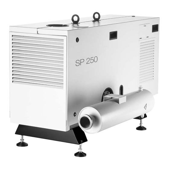
- Page 1 SCREWLINE SP 250 O Version Dry Compressing Screw Vacuum Pump Operating Instructions 17200146_002_C0 115 019...
- Page 2 Connections at the Intake Side 3.3.2 Connections at the Delivery Side (Exhaust Electrical Connection 3.4.1 Motor Protection 3.4.2 Star/Delta Start-up Circuit 3.4.3 Soft Start 3.4.4 Mains Connection 3.4.5 Power Failure 3.4.6 Operation with a Frequency Converter (FC Operation) 17200146_002_C0 - 02/2017 - © Leybold...
- Page 3 Checking and Cleaning the Gas Ballast Filter Replacing the Filter Cartridge in the Pressure Reducer Checking the SP-Guard Service at Leybold Maintenance Schedule Troubleshooting Waste Disposal EU Declaration of Conformity These Operating Instructions are the original instructions. 17200146_002_C0 - 02/2017 - © Leybold...
- Page 4 Operating Instructions and follow the information so as to ensure optimum and safe working right from the start. The Leybold SCREWLINE SP 250 have been designed for safe and efficient operation when used properly and in accordance with these Operating Instructions.
- Page 5 Hot surface Do not touch. Allow this area to cool before servicing Burn hazard Hot surface inside. Do not touch. Wear protective equipment. Reactive or corrosive media must not be pumped with this pump. 17200146_002_C0 - 02/2017 - © Leybold...
- Page 6 Connect the pump so that it not will restart automatically after a mains power failure, once the power returns. Overhead load Transport the pump only at the two crane eyes or with a forklift secured on a suitable palette. 17200146_002_C0 - 02/2017 - © Leybold...
- Page 7 The crane eyes of the screw pump must never be used to lift any pump combinations (Roots pump + backing pump). 17200146_002_C0 - 02/2017 - © Leybold...
- Page 8 After having connected the motor and each time after having made changes to the wiring, check the direction of rotation. If the direction of rotation is wrong, the pressure can increase on the intake side. Moreover, the pump can suffer severe damage. 17200146_002_C0 - 02/2017 - © Leybold...
- Page 9 When nitrogen is used as the purge gas or as the gas ballast, small quantities of nitrogen can escape to the surroundings. Ensure sufficient ventilation for the room in which to pump has been installed. 17200146_002_C0 - 02/2017 - © Leybold...
- Page 10 When pump- ing harmful gases, the operator must ensure that such a malfunction cannot occur, respectively that leaks at the pump will not be a hazard. 17200146_002_C0 - 02/2017 - © Leybold...
- Page 11 Safety Information Leybold is not in a position to perform servicing (repairs) and waste disposal of radioactively contaminated pumps. Both needs to be ensured from the side of the user. When disposing the pump, used lubricants and used oil filters observe the applicable environment regulations.
- Page 12 For proper connection, a suitable motor protection switch must be used. Set this motor protection switch in agreement with the informa- tion provided on the motor nameplate. Connect the pump to the correct mains voltage and mains frequency. 17200146_002_C0 - 02/2017 - © Leybold...
- Page 13 Pressures given in bar or mbar are absolute values. If exceptionally a gauge pressure is meant, a “g” is added (bar(g) = bar (gauge) = bar overpressure) 17200146_002_C0 - 02/2017 - © Leybold...
- Page 14 Work processes in which oxygen is used need to be designed such that the workers are not endangered by an atmosphere enriched with oxygen. 17200146_002_C0 - 02/2017 - © Leybold...
- Page 15 The fire hazard increases with increasing oxygen concen- trations. The fire hazard in oxygen containing system sections increases with increasing oxygen concentration, increasing temperature and increasing pressure of the oxygen and the oxygen mixtures. 17200146_002_C0 - 02/2017 - © Leybold...
- Page 16 (switch off) the pump. Deploy a suitable motor control system. Once per year the sensors of the SP-Guard must be checked as to proper operation. For this please contact the Leybold after sales ser- vice. Before commissioning the pump, remove the two bags with desic- cant which have been placed in the exhaust flange of the pump.
- Page 17 Use only original SP 250 seals from Leybold, since only these have been qualified for oxygen operation. When connecting the pump to a vacuum chamber, a suitable valve...
- Page 18 The SP 250 is air-cooled, a radial fan supports the cooling effect for the hou- Cooling sing which is equipped liberally with cooling fins. 17200146_002_C0 - 02/2017 - © Leybold...
- Page 19 (fig. 1.2) so that the chamber volume is already reduced at low pressures (fig. 1.3c). In this way a power consumption can be attained which is comparable to that of rotary vane pumps. 17200146_002_C0 - 02/2017 - © Leybold...
- Page 20 Fig. 1.2 Compression principle and the direction of pumping action within a screw pump without inner compression with inner compression against with inner compression the face side of the pump along the rotor chamber (SCREWLINE) Fig. 1.3 pV diagrams of screw pumps 17200146_002_C0 - 02/2017 - © Leybold...
- Page 21 Temperature sensor in the motor coil PTC 160 °C - 5 °C PTC 160 °C - 5 °C Operating mode S1 (continuous operation) S1 (continuous operation) Operating agents Cooling Approved type of oil: LVO 210 17200146_002_C0 - 02/2017 - © Leybold...
- Page 22 Power rating during operation Power rating when being energised 80 W Type of protection IP 65 acc. to IEC 60259 Cable diameter 6-7 mm Electrical connector with Varistor Bürkert, type 8376 acc. to DIN 43650 Form A 17200146_002_C0 - 02/2017 - © Leybold...
- Page 23 Electrical connector Festo, Type 2508, IP 65 Connection thread/gas supply G 1/8" - inside thread / 6 mm quick connector Purge gas pressureto be set up 2.5 bar Purge gas volume flow 26 Std. l/min 17200146_002_C0 - 02/2017 - © Leybold...
- Page 24 SP 250/50 Hz mbar Intake pressure Pressure Fig. 1.4 Pumping speed curves > 500 68-75 1348 > 500 > 500 (Dimensions in mm) Serviceabstand > 900 Clearance for maintenance work Dimensional drawing Fig. 1.5 17200146_002_C0 - 02/2017 - © Leybold...
- Page 25 For the purpose of shipping the pump, the pump has been affixed to a spe- cial pallet. Retain this pallet in case the pump needs to be returned. 17200146_002_C0 - 02/2017 - © Leybold...
- Page 26 The gas ballast valve is used for the purpose of avoiding condensation within the pump. Purge gas facility Purge gas prevents that process gas escapes via the two shaft seals to the environment and protects components and seals against corrosion. 17200146_002_C0 - 02/2017 - © Leybold...
- Page 27 Connection PTC motor winding SP-GUARD Pressure reducer purge gas Purge gas pressure switch Exhaust pressure switch Vibration Oil level Oil temperature sensor sensor sensor Fig. 1.8 Components of the monitoring system at the SP 250 (covers removed) 17200146_002_C0 - 02/2017 - © Leybold...
- Page 28 Roots pump adapter for RUVAC 1001/501 119 022 ■ Stability of the pump when using Leybold accessories is ensured. If other accessories are fitted then the user himself will be respon sible for maintaining pump stability. Wearing Parts and Original Spare Parts...
- Page 29 After transport ensure that the pump is placed uniformly. Single sided or point-like loads as well as high-end dynamic stresses caused by setting the pump down hard on its feet, for example, must be avoided. 17200146_002_C0 - 02/2017 - © Leybold...
- Page 30 When shelving the pump for prolonged periods, drain out of the oil from the pump. Package in the pump air-tight in polyethylene foil. Storage conditions Temperature -20 °C to + 60 °C Storage site Maximum atmospheric humidity 95 %, non-condensing 17200146_002_C0 - 02/2017 - © Leybold...
- Page 31 Technical Data. In all other operating modes and with other equipment, higher values may be attained. Suitable hearing protection measures must be intro- duced. 17200146_002_C0 - 02/2017 - © Leybold...
- Page 32 (freeze) drying, packaging, research and development etc. The SP 250 O versions have been specially designed and manufactured so as to comply with the requirements of regulations BGR 500 and DIN EN 1012-2 in consideration of pumping oxygen. 17200146_002_C0 - 02/2017 - © Leybold...
- Page 33 The materials for the connecting lines must be capable of sustaining the medium which is being pumped. The pipe connections shall be connected to the pump free of any mechanical tensions. 17200146_002_C0 - 02/2017 - © Leybold...
- Page 34 Remove protection foil and desiccant from the discharge flange. The pressure in the discharge line must not exceed 200 mbar are above CAUTION the ambient pressure. The discharge line must not be blocked or constrict- 17200146_002_C0 - 02/2017 - © Leybold...
- Page 35 The number of operating hours of the pump is acquired through the SP-Guard. The local connection conditions will possibly necessitate means for the pur- pose of reducing the surge currents upon switching the pump on. 17200146_002_C0 - 02/2017 - © Leybold...
- Page 36 The line cross-section for the mains power supply needs to be calculated in consideration of the cable length and the available mains circuit breaker. Using a mains power supply line having a cross-section of at least 4 x 6 mm is recommended. 17200146_002_C0 - 02/2017 - © Leybold...
- Page 37 I / A I / A ∆ ∆∆ ∆ ∆∆ ∆ ∆ ∆∆ ∆∆ U / V U / V Diagram 3.1.1 Characteristic of the motor protection switch for delta circuit (Symbol ∆ respectively ∆∆ ) 17200146_002_C0 - 02/2017 - © Leybold...
- Page 38 3~ / 210 V 60 Hz For continuous operation! For starting only! Temperature sensor integrated in the coil. Caution Do not apply voltages in excess of 2.5 V Fig. 3.4 Mains connection (connection diagrams in the junction box) 17200146_002_C0 - 02/2017 - © Leybold...
- Page 39 Observe the direction of rotation of the running down fan. The correct direc- tion of rotation is indicated by an arrow in the junction box. In the case of a wrong connection, rewire. Close the housing again. 17200146_002_C0 - 02/2017 - © Leybold...
- Page 40 In order to reduce the level of electromagnetic interference, shielded motor cables, shielded cable feedthroughs, motor filters and EMC-compliant ground connections between FC and pump will be necessary. Always also observe the information given in the Operating Instructions for the frequency converter. 17200146_002_C0 - 02/2017 - © Leybold...
- Page 41 If the temperature of the oil deviates during normal loads and ambient con- NOTICE ditions from the process dependent standard values, the oil cooler should be checked to see if it has accumulated any dirt. 17200146_002_C0 - 02/2017 - © Leybold...
- Page 42 24 V DC 24 V DC pressure switch schalter 4.5 W 4,5 W Oil tempera - Öltemperatur- ture sensor sensor Oil level Ölstand- switch schalter Fig. 3.6 Block diagram for the screw pump O version 17200146_002_C0 - 02/2017 - © Leybold...
- Page 43 Switching output S1 (warning) red/blue Switching output S2 (error) white/green Switching output S3 (watchdog) brown/green Switching output S4 (pump on) yellow/brown 0 V (GND for PLC controller) Not connected Shield For connection, see fig. 3.8 17200146_002_C0 - 02/2017 - © Leybold...
- Page 44 1 V below the power supply voltage level and the low level is at approximately 1 V. The maximum current rating is 40 mA. The outputs are protected by means of semiconductor fuses. 17200146_002_C0 - 02/2017 - © Leybold...
- Page 45 SP 250 values 40 to 60 digits Warning limit, vibrations digits Failure limit, vibrations 0,2 s Hysteresis Vibration measurement 30 to 60 °C Warning limit, oil temperature °C Failure limit, oil temperature 17200146_002_C0 - 02/2017 - © Leybold...
- Page 46 • Push the flat gasket onto the connector pins Compression ring • Insert the connector socket up to the stop Sealing ring • Secure with cylinder head screw M 3 x 30 Collet Union nut Fig. 3.11 Fitting the connector 17200146_002_C0 - 02/2017 - © Leybold...
- Page 47 Pressure connection for purge gas - G 1/8" inside thread, respectively 6 mm plug-in connector. Manual drain for condensate Fig. 3.12 Purge gas connection and condensate drain at the supply unit 17200146_002_C0 - 02/2017 - © Leybold...
- Page 48 IP pump and in line with IP 65 requirements. The valve is of the normally closed type. In the control arrangement needs to be implemented such that before switch ing on the screw pump, the purge gas valve opens as otherwise the SP-Guard will output an error message. 17200146_002_C0 - 02/2017 - © Leybold...
- Page 49 When doing so make sure that all aids used are clean so as to avoid con- taminating the oil. Use only lubricating oil which has been approved by Leybold. The gear oil should be filled in at room temperature. At lower temperatures, the oil is thicker so that there then is the risk of overfilling gear chamber with oil.
- Page 50 Minimum mark at the oil sight glass Float ■ during standstill Minimum mark at the oil sight glass ■ during operation Oil drain plug Fig. 4.2 Oil level at the oil sight glass after the SP 250 17200146_002_C0 - 02/2017 - © Leybold...
- Page 51 The gear housing is vented in the vicinity of fan wheel through two channels on the side opposite the exhaust. By design, small amounts of gear oil may escape through this vent. This will not adversely affect operation of the pump. 17200146_002_C0 - 02/2017 - © Leybold...
- Page 52 (3 seconds), and then short twice. A confirmation of the resetting pro- cess will be indicated on the display for approximately 5 seconds. Status Messages on the Display of the SP-Guard The number of operating hours is constantly indicated on the display. 17200146_002_C0 - 02/2017 - © Leybold...
- Page 53 It must be ensured that the pressure does not exceed p + 200 mbar CAUTION and that the temperature does not exceed 60 °C. Typical gas ballast con- sumption is at approximately 26 Std. l/h. 17200146_002_C0 - 02/2017 - © Leybold...
- Page 54 An error message will be displayed (and must be acknowledged), if the purge gas will be turned off prior to the SP Guard or turned on after the SP Guard. 17200146_002_C0 - 02/2017 - © Leybold...
- Page 55 If much condensate is col- lected, the condensate separator will have to be checked regularly. 17200146_002_C0 - 02/2017 - © Leybold...
- Page 56 In the case of prolonged standstill times (over three weeks) further mea- sures besides letting the pump run idle need to be introduced for the pur- pose of avoiding corrosion due to standstill, see Section 2 “Storing”. For this please contact Leybold for advice. Switch off power supply for the SP-Guard ■...
- Page 57 All work within the pump should be left to suitably trained staff. In this con- text we would like to inform you about practical seminars offered by Leybold in which maintenance, repair and testing of the SP 250 are cov- ered by qualified instructors. Improperly performed maintenance or repair work will void any warranty claims.
- Page 58 Place a sufficiently large collecting vessel (about 20 litres) under the pump. When disposing of the waste oil observe the applicable environment pro- tection regulations. Use only lubricants approved by Leybold. NOTICE To change the oil, the cover section on the discharge side needs to be disas- sembled, see fig.
- Page 59 Pull the filter insert out. Push the new filter insert on until it positively engages. Replace the O-ring of the filter housing. Screw the filter housing on up to the stop and tighten. 17200146_002_C0 - 02/2017 - © Leybold...
- Page 60 A dirty cooler may cause increased oil and pump temperatures and impair operation and reduce the service life of the pump. The oil cooler can be cleaned with an industrial vacuum cleaner after having removed one cover section. 17200146_002_C0 - 02/2017 - © Leybold...
- Page 61 Cleaning the Dust Filter in the Intake Line (optional) The dust filters which are installed upstream of the pump need to be checked regularly for contamination and cleaned as required. 17200146_002_C0 - 02/2017 - © Leybold...
- Page 62 Re-seal the thread with Teflon tape and fit the filter element once more. Fit the dust cap again and affix it with the locking clips. The cover is fitted in the reverse order as described in Section 4.1.1. 17200146_002_C0 - 02/2017 - © Leybold...
- Page 63 150 digits the pump is shut down. If these functions of the SP-Guard are not operative, please contact the Leybold Service. If the pump does not shut down as intended, check the control and power circuitry.
- Page 64 In the next step slowly reduce the pressure, as soon as the switching thre- shold is attained, a flow of 16 Std. l/min or more must be present. If this is not the case, please contact the Leybold Service. d) Discharge pressure sensor In order to check the discharge pressure, the pressure sensor must be remo- ved and compared against a reference pressure.
- Page 65 After 10 years, the SP-Guard must be replaced. Service at Leybold If you send a pump to Leybold indicate whether the pump is free of sub- stances damaging to health or whether it is contaminated. If it is contaminated also indicate the nature of the hazard. To do so, you must use a preprinted form which we shall send to you upon request.
- Page 66 In the case of oxygen operation, the Viton seals in contact with the medium need to be replaced after three years by our after sales service since these are subject to ageing. Only original SP 250 seals must be used since these have been qualified for oxygen operation. 17200146_002_C0 - 02/2017 - © Leybold...
- Page 67 Exhaust pressure too high or too low. Purge gas Valve has not switched. Check valve, if required connect correctly. Electrician gauge does not Purge gas supply has failed. Ensure a proper purge gas supply. indi cate any pressure. 17200146_002_C0 - 02/2017 - © Leybold...
- Page 68 Check if rotors turn freely, measure motor Notice: Do not restart the pump after the resistance, replace motor if required. Service motor protection switch has tripped without having repaired the cause of the tripping. 17200146_002_C0 - 02/2017 - © Leybold...
- Page 69 Defective silencer. Repair silencer. High gas throughput with the discharge line Install discharge line or silencer. open, without silencer. Oil film in the Oil ingress after longer operation. No need for action. junction box. 17200146_002_C0 - 02/2017 - © Leybold...
- Page 70 Waste oil from vacuum pumps must not be mixed with other substances or materials. Waste oil from vacuum pumps (Leybold oils which are based on mineral oils) which are subject to normal wear and which are contaminated due to the influence of oxygen in the air, high temperatures or mechanical wear must be disposed of through the locally available waste oil disposal system.
- Page 71 EU Declaration of Conformity 17200146_002_C0 - 02/2017 - © Leybold...
- Page 72 Notes 17200146_002_C0 - 02/2017 - © Leybold...
- Page 73 Person to contact: Calibration: Factory-calibr. Phone : Fax: Quality test certificate DIN 55350-18-4.2.1 End user: A. Description of the Leybold product: Failure description: Material description : Additional parts: Catalog number: Serial number: Application-Tool: Type of oil (ForeVacuum-Pumps) : Application- Process: B.
- Page 74 Sales and Service Germany America Great Britain Leybold Japan Co., Ltd. Tsukuba Technical Service Center 1959, Kami-yokoba Leybold UK LTD. Leybold GmbH Tsukuba-shi, Ibaraki-shi 305-0854 Unit 9 Sales, Service, Support Center (3SC) Japan Silverglade Business Park Leybold USA Inc. Bonner Strasse 498...
Need help?
Do you have a question about the SCREWLINE SP 250 O2 and is the answer not in the manual?
Questions and answers