
Related Manuals for BED BATH & Beyond 1061120201B


Summary of Contents for BED BATH & Beyond 1061120201B
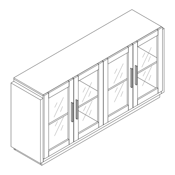
- Page 1 Sideboard 1061120201B Assembly Instructions - Please keep for future reference 1061120202B Dimensions Width - 63.7inch Depth - 15.7inch Height - 32inch Important – Please read these instructions fully before starting assembly 1016625# Issue 1 - 08/20/23...
- Page 2 Safety and Care Advice Important – Please read these instructions fully before starting assembly • Check you have all the • During assembly do not stand • To reduce components and tools listed on or put weight on the product, the likelihood of the following pages.
- Page 3 Components - Panels Please check you have all the panels listed below 1 (700X385X15mm)X1 2 (700X385X15mm)X1 3 (750X120X15mm)X1 4 (1750X120X15mm)X1 5 (750X60X15mm)X1 6 (750X60X15mm)X1 7 (700X385X15mm)X1 8 (760X300X2.7mm)X4 9 (1546X370X15mm)X1 10 (1546X45X15mm)X1 11 (1546X80X15mm)X2 12 (340X80X15mm)X3 13 (720X385X37mm)X1 14 (720X385X37mm)X1 15 (1546X385X15mm)X1 16 (749X360X15mm)X2 17 (720X385X15mm)X1 18 (720X385X15mm)X1...
- Page 4 Components - Fittings Please check you have all the hardware listed below Note: The quantitie below are the correcet amount to complete the assembly. In some cases more fittings may be supplied than are required. Male Camlock x 54 Female Camlock x 54 Dowel x 33 5*45mm Screw x 6 Shelf Support Pin x 8...
- Page 5 Using Camlocks Step 1 Step 2 DO NOT OVER TIGHTEN. Connect the male Push the male camlock NE PAS SERRER EXCESSIVEMENT. camlock as diected in into the entry hole. the assembly instructions using a scewdriver . Step 4 Step 3 Insert the female Turn the female camlock camlock as shown in the...
- Page 6 Assembly Instructions...
- Page 7 Assembly Instructions Step 1 A x 6 C x 8 Step 2 A x 6 C x 4...
- Page 8 Assembly Instructions Step 3 C x 7 Step 4 B x 3...
- Page 9 Assembly Instructions Step 5 B x 3 Step 6 B x 3...
- Page 10 Assembly Instructions Step 7 B x 3 Step 8...
- Page 11 Assembly Instructions Step 9 A x 16 C x 2 Step 10 A x 14 C x 2...
- Page 12 Assembly Instructions Step 11 B x 4 Step 12 F x 6...
- Page 13 Assembly Instructions Step 13 B x 12 Step 14 C x 10...
- Page 14 Assembly Instructions Step 15 B x 14 Step 16 I x 12...
- Page 15 Assembly Instructions Step 17 J x 4 Step 18 J x 4...
- Page 16 Assembly Instructions Step 19 O x 1 Step 20...
- Page 17 Assembly Instructions Step 21 O x 1 Step 22 A x 12...
- Page 18 Assembly Instructions Step 23 B x 12 Step 24 D x 8...
- Page 19 Assembly Instructions Step 25 Step 26 G x 2 E x 8 K x 4...
- Page 20 Assembly Instructions Step 27 G x 2 E x 8 L x 4 Step 28 E x 16...
- Page 21 Assembly Instructions Step 29 E x 16 Step 30 N x 16...
- Page 22 Assembly Instructions Step 31 H x 4 Step 32 The unit is floor standing, but it is M x 2 recommended that the unit is secured to the wall. 1. Move the unit into desired position. 2. Mark the wall with a suitable scribe the position of the fixing holes.
- Page 23 Assembly Instructions Step 33 The unit is floor standing, but it is M x 2 Wall recommended that the unit is secured to the wall. 1. Move the unit into desired position. 2. Mark the wall with a suitable scribe the Wall position of the fixing holes.
Need help?
Do you have a question about the 1061120201B and is the answer not in the manual?
Questions and answers