Advertisement
Advertisement
Table of Contents

Related Manuals for APRILIA RX 50 RACING - 2003


Summary of Contents for APRILIA RX 50 RACING - 2003
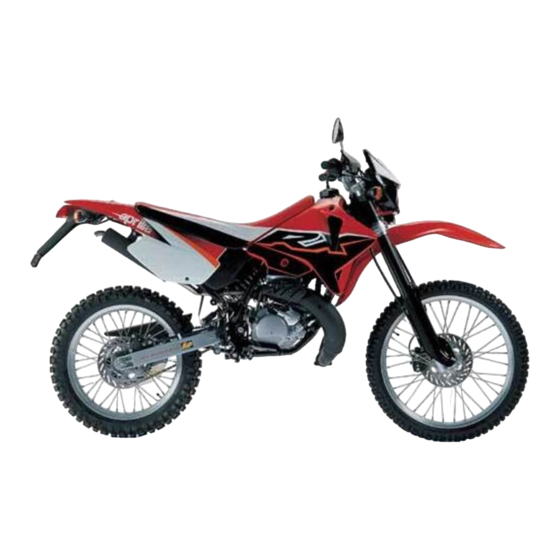
- Page 1 Racing 8202401...
-
Page 2: Catalytic Muffler
(N.O.R.M.) AND 85 (N.O.M.M.) AND HIGH PERFORMANCE SYNTHETIC OIL FOR 2 STROKE ENGINES. THE USE OF FUELS AND LUBRICANTS DIFFERENT FROM THOSE INDICATED CAUSES SEVERE FUNCTIONAL INCONVENIENCES TO THE VEHICLE AND THE VOIDING OF THE aprilia GUARANTEE. To have the catalytic converter functioning correctly for long periods and to reduce possible problems regarding the contamination of the thermal unit and of the exhaust, it is necessary to avoid covering long distances with the engine running at constantly low rpm. -
Page 3: Catalytic Silencer
CATALYTIC SILENCER The catalytic version of the RX50 Racign is fitted with a silencer with metal catalytic converter of the “platinum-rhodium bivalent” type. This device provides for the oxidation of the CO (carbon monoxide) and of the HC (unburned hydrocarbons) contained in the exhaust gases, changing them into carbon di- oxide and steam, respectively. - Page 4 To keep your aprilia vehicle always in perfect operat- ing conditions, we advise you to insist on Original Spares and to have repairs carried out only by aprilia Authorized Outlets and Official Dealers. When ordering spare parts from the Dealers, always...
- Page 5 Carefully observe the instructions preceded by the VERSION: following warning signs: Italy Holland Croatia Safety norms and regulations to protect United Switzerland Australia the driver and other people from severe Kingdom injuries or grave risks United States Austria Denmark of America Caution norms and suggestions to avoid Portugal Japan...
-
Page 6: Table Of Contents
CONTENTS Pag. CATALYTIC MUFFLER..........2 CATALYTIC SILENCER..........3 ARRANGEMENT OF THE CONTROLS ....18 INSTRUCTIONS FOR USE........41 MAINTENANCE ............46 IDENTIFICATION DATA ........... 49 ELECTRICAL SYSTEM..........68 CLEANING ..............74 LONG INACTIVITY............ 74 TECHNICAL FEATURES .......... 75... - Page 8 BASIC SAFETY RULES To drive the vehicle it is necessary to be in posses- sion of all the requirements prescribed by law (driving licence, minimum age, psychophysical ability, insu- rance, state taxes, vehicle registration, number plate, etc.). Gradually get to know the vehicle by driving it first in areas with low traffic and/or private areas.
- Page 9 Most road accidents are caused by the driver»s lack of experience. NEVER lend the vehicle to beginners and, in any ca- se, make sure that the driver has all the requirements for driving. Fig. 3 Rigorously observe all road signs and national and local road regulations.
- Page 10 Avoid obstacles that could damage the vehicle or make you lose control. Avoid riding in the slipstream created by preceding vehicles in order to increase your speed. Fig. 5 Always drive with both hands on the han- dlebars and both feet on the footrests (or on the rider’s footboards), in the correct driving posture.
- Page 11 The driver should pay attention and avoid distrac- tions caused by people, things and movements (ne- ver smoke, eat, drink, read, etc.) while driving. Fig. 7 Use only the vehicle»s specific fuels and lubricants indicated in the "LUBRICANT CHART"; check all oil, fuel and coolant levels regularly.
- Page 12 If necessary, have the vehicle inspected by an Con- cessionario Ufficiale aprilia who should carefully check the frame, handlebars, suspensions, safety parts and all the devices that you cannot check by yourself.
- Page 13 Any modification of the vehicle and/or the removal of original components can compromise vehicle perfor- ONLY ORIGINALS mance levels and safety or even make it illegal. We recommend respecting all regulations and natio- nal and local provisions regarding the equipment of the vehicle.
- Page 14 (aprilia genuine accessories). Fig. 14...
- Page 15 LOAD Be careful and moderate when loading your luggage. Keep any luggage loaded as close as possible to the center of gravity of the vehicle and distribute the load uniformly on both sides, in order to reduce umbalan- ce to the minimum. Furthermore, make sure that the load is firmly secured to the vehicle, especially during long trips.
- Page 16 Do not carry any bag if it is not tightly secured to the vehicle. Do not carry bags which protrude too much from the luggage-rack or which cover the lights, horn or indi- cators. Do not carry animals or children on the glove com- partment or on the luggage rack.
- Page 17 Low pressure can cause handling prob- TYRE INFLATION PRESSURE lems and the tendency to weave and in Driver only extreme cases loss of control. Kind of drive Moreover this will cause a great increase of roll- Front Rear ing friction. Off-road 1,3 bar 1,4 bar...
-
Page 18: Arrangement Of The Controls
ARRANGEMENT OF THE CONTROLS The control devices are positioned as indicated in fi- gures 3 and 4, as follows: 1) Clutch lever 2) Cold start control 3) Front brake lever 4) Twist grip 5) Rear brake pedal 6) Kick-starter 7) Gear pedal Fig. - Page 19 1) Cold start lever ( ) 2) Multifunction computer 3) Ignition / steering lock switch ( - 4) Dimmer light switch ( ) and high beam sig- nalling push button ( 5) Horn push button ( 6) High beam warning light ( 7) Speedometer/odometer with trip counter 8) Neutral indicator warning light ( ) 9) Mixer oil reserve warning light (...
- Page 20 MULTIFUNCTION COMPUTER The display is provided with an automatic shutoff function. In case the vehicle or the display are left unused for more than 30 min- 88:88 88:88 ASS PD MS ASS PD MS AR TT AR TT utes, the display will be automatically disabled. All the pre-set data will nevertheless be stored.
- Page 21 By simply setting the front wheel circum- ference, two different types of vehicles, bike 1 and bike 2, can be stored inside the multi- function computer memory. 88:88 88:88 Left display: Vehicle (1), total distance covered (2), AR TT AR TT partial distance covered (3) and maintenance func- tions (4) can be selected;...
- Page 22 START-UP SETTING Metric system setting (KM/H or MPH) Keep the three push buttons simultaneously pres- ◆ sed for about 2 seconds, then press any of them KM/H to start settings. Press left push button to change the unit of mea- ◆...
- Page 23 Setting the “WS” wheel diameter To change the flashing value, press the left push ◆ button. 11 11 Press right push button to go to next value and ◆ KM/H then press left push button again to change this value. MODE Pre-set value 2170.
- Page 24 Time setting Press left push button to select time displaying ◆ (24h or 12 h). Press right push button to set the ≈hour∆. Press ◆ 12:00:- - left push button to change the value. Press right push button to set the ≈minutes∆. ◆...
- Page 25 Preventative lubrication check The preventative lubrication check is alrea- dy pre-set after the first 100 km (60 mi) for vehicle 1 and after the first 300 km (200 mi) for vehi- cle 2. To change lubrication interval, refer to page 30 MODE (STANDARD SETTING).
- Page 26 Preventative maintenance check The preventative maintenance check is already pre-set after the first 300 km (200 mi) for vehicle 1 and after the first 990 km (600 mi) for vehicle 2. To change maintenance check interval, refer to MODE page 30 (STANDARD SETTING). Press left push button to modify the value.
- Page 27 Checking the total distance covered (ODO) Press left push button to modify the value. ◆ Press right push button to shift to next value. ◆ Keep centre ≈MODE∆ push button pressed for ◆ about 1.5 seconds to confirm. Then start total race time setting (ART).
- Page 28 Checking the total race time (ART) Press left push button to modify the value. ◆ Press right push button to shift to next value. ◆ 00:00 Keep centre ≈MODE∆ push button pressed for ◆ about 2 seconds to confirm. Start-up setting is now completed.
- Page 29 Programming the second vehicle Keep the right push button pressed for about 5 se- 0:00 conds. The ≈WS∆ wheel diameter value of the second KM/H vehicle will appear on the left display. The menu rela- 11:53:48 ting to the second vehicle will be automatically ena- bled after a few seconds.
- Page 30 STANDARD SETTING Keep the two outer push buttons pressed for about 2 seconds to enable the STAN- DARD SETTING programme. This menu will allow you to modify the wheel diame- MODE ter, the time setting, the vehicle lubrication and main- tenance interval, the total distance covered (ODO) and the total race time (ART).
- Page 31 PARAMETERS SETTING/DISPLAYING Press the centre MODE push button to 0:00 scroll the different setting screens. KM/H 11:53:48 MODE During operation, screen (A) - showing the distance covered after the last resetting (TT), the current spe- ed, time and partial race time (RT) - will be displayed. 0:00 Press centre push button ≈MODE∆...
- Page 32 Keep centre push button ≈MODE∆ and right push but- ton simultaneously pressed for about 2 seconds to shift to screen (D) - showing the preventative mainte- 30:42 nance check function - and press them again to shift KM/H again to screen (E) showing the preventative lubrica- 11:49:08 tion check function.
- Page 33 DISABLING THE SCHEDULED MAINTENANCE SERVICES Whenever the scheduled maintenance or lubrication service intervals are not respected, the relating value will start flashing on the left display. MODE To switch this value off, keep the right and left push button simultaneously pressed for about 2 seconds. MODE Keep centre push button ≈MODE∆...
- Page 34 CHRONOMETER The multifunction computer is equipped with a chro- 30:42 nometer, to be displayed on screen (B) together with trip meter (TT). KM/H 11:49:08 Press left push button to enable chronometer. ◆ Press centre push button ≈MODE∆ to display scre- ◆...
- Page 35 RESETTING THE PARTIAL VALUES This function is used to reset the partial values stored 30:42 inside the computer memory. In particular: √ Partial distance covered (DST) KM/H 11:53:48 √ Trip meter (TT) √ Partial race time (RT) MODE √ Maximum speed (MS) √...
- Page 36 ALIGNING THE PARTIAL VALUES (TRIP) The partial distance covered (DST) can be modified by increasing or decreasing the value appearing on 30:47 the display. This function can be used during compe- KM/H 11:49:13 titions to make the displayed value match the one re- lating to the racetrack.
- Page 37 BACKLIGHTING Press right push button to enable display backlight- MODE ing, The light will be automatically switched off after 4 seconds. 88:88 ASS PD MS AR TT KM/H 88:88:88 Fig. 41...
- Page 38 CHANGING THE BATTERY Remove headlight fairing. ◆ Loosen the 2 cross-head screws between instru- ◆ ment holder and metal plate. Disconnect the 2-way connector from speedome- ◆ ter transmission unit. To remove the digital instrument from its holder, ◆ slightly press on LCD side. Disconnect the ≈sliding shoe∆...
- Page 39 IGNITION SWITCH / STEERING LOCK / STEERING LOCK LIGHT SWITCH Never turn the key to the " " position The ignition switch can be turned to three positions: while driving, in order to avoid losing First click clockwise = ≈ ≈ (start) ◆...
- Page 40 CRASH-HELMET LOCK (Fig. 43) Using the ignition key it is possible to have access to the crash-helmet lock positioned on the rear part of the vehicle. Fig. 43 GLOVE / TOOL COMPARTMENT (Fig. 44) It is positioned on the inner part of the left side of the fairing.
-
Page 41: Instructions For Use
After the first month of use, let the 1 servicing cou- that the tyres are inflated to the correct pressure pon be made by an aprilia Official Dealer. (see ≈TYRE INFLATION PRESSURE∆) and fill the fuel tank with premium grade petrol (see ≈TECH- If there is no oil left in the mixer oil tank, NICAL DATA∆). - Page 42 PRELIMINARY CHECKING OPERATIONS Component Check Page F r o n t a n d r e a r d i s c Check the functioning, the idle stroke of the control levers, the fluid level and 54-55 brakes make sure there are no leaks. Check the wear of the pads. If necessary, top up 56-57 the fluid tank.
- Page 43 STARTING (Fig. 45) Open the fuel coock on the tank (Fig. 45). ◆ Insert the ignition key and turn to ≈ ∆ position. ◆ In case of cold start refer to page 44 (COLD ◆ START), switch the cold start control on. Place gears in neutral position, (neutral indicator ◆...
- Page 44 Strongly push the start pedal, then release it im- ◆ mediately. If necessary, repeat this operation until engine is started. Keep front brake lever pulled and do not open ◆ throttles until departure. Do not accelerate abruptly with the engi- ne cold.
- Page 45 Fig. 47 Before riding the motor cycle we advise you to get to know the controls and all their functions as explained in this manu- al. Contact your aprilia Offical Dealer if there is anything you do not understand.
-
Page 46: Maintenance
If you need assistance or technical advice consult your aprilia Official Dealer, who can ensure you It is absolutely forbidden to put the vehi- cle on the stand while being seated on it. - Page 47 24 months (after 1 month) OPERATIONS TO BE CAR- Battery - Terminal fastening - √ Electrolyte level RIED OUT BY THE aprilia Of- ficial Dealer (WHICH CAN BE every 3 months: Spark plug every 6 months: CARRIED OUT EVEN BY THE USER).
- Page 48 OPERATIONS TO BE CAR- End of running- Every Every Component in period RIED OUT BY THE aprilia Of- 12 months 24 months (after 1 month) ficial Dealer. Rear shock absorber √ √ Carburettor √ √ Transmission cables and controls √...
-
Page 49: Identification Data
IDENTIFICATION DATA It is a good rule to write down the frame and engine numbers in the space provided in this manual. The frame number can be used for the purchase of spare parts. Do not alter the identification numbers if you do not want to incur severe penal and administrative sanctions. - Page 50 ◆ In case of oil leakages or malfunctions, Place a suitably large container (min. 1000 cm ◆ contact your aprilia Official Dealer. under the engine to catch the old oil. Unscrew the drain plug (3) placed on the bottom. ◆...
- Page 51 (Fig. 52). If it is not possible to adjust the clutch by means of the adjusters, contact your aprilia Official Dealer Fig. 51 The clutch must be adjusted when it does not "re- lease" correctly and the vehicle tends to move even with the clutch pulled.
- Page 52 SEPARATE LUBRICATION (Fig. 53-56) Top up the mixer oil tank every 500 km. The vehicle has a separate lubrication system which includes an mixer oil tank (Fig. 53) (1,3 with a re- serve of 0,5 ) and a variable-capacity oil supply pump (the capacity varies according to the number of revs of the motor and the opening of the throttle) (Fig.
- Page 53 Unscrew the drainage screw (1) and at the same ◆ time completely rotate the pump control lever (2) until the oil drains off, then tighten the screw again. Keep the pump lever rotated until all traces of air ◆ bubbles have completely disappeared from the carburettor supply pipe.
- Page 54 (3). ADJUSTING THE REAR BRAKE Check the braking efficiency. (Fig. 55) If necessary, contact your aprilia Official Dealer. The brake pedal is positioned ergonomically during the assembly phase. If necessary, it is possible to adjust the height of the...
- Page 55 CHECKING AND BLEEDING THE FRONT AND REAR BRAKE (Fig. 56) The vehicle is provided with a hydraulically controlled front and rear disc brake. The brake fluid level in the pump tank must be checked from time to time. After the first 500 km or whenever an excessive ◆...
- Page 56 CHECKING THE BRAKE PAD WEAR (Fig. 57) Check brake pads for wear every 2,000 km. In case of off-road use, with mud or sand, check brake pads after every ride. The pads present a groove that must always be visi- ble.
- Page 57 From above, on the rear part, for rear brake cali- ◆ per. The excessive wear of the friction mate- rial would cause the contact of the pad metal support with the disc, with conse- quent metallic noise and production of sparks from the caliper;...
- Page 58 ADJUSTING THE REAR SUSPENSION (Fig. 59) The rear suspension comprises a single spring- shock absorber unit and a lever unit with A.P.S. The standard rear suspension is suitable for a driver weighing about 75 kg. In case your weight or riding style are different from the standard setting, change shock absorber spring length by turning ring nut (4) and (5) or rebound adju- ster by turning knob (1).
- Page 59 CHAIN ADJUSTMENT (Fig. 60) Stand the vehicle in an upright position and com- ◆ pletely extend the rear suspension. Check that the vertical movement in the lower part ◆ of the chain, at a point mid-way between the pin- ion and the crown, is about 30-35 mm. If this distance is not correct, proceed as follows: Loosen the rear wheel pin fastening nut.
- Page 60 CHAIN LUBRICATION (Fig. 61) Proceed to chain lubrication frequently (see ≈LU- BRICANT CHART∆), every 4,000 km, every time the vehicle is used off-road on mud or sand. Fig. 61 CHAIN CHECKING (Fig. 62) From time to time check the wear condition of the chain;...
- Page 61 AIR FILTER REMOVING AND CLEANING (Fig. 63) The correctly performed dismantling and cleaning of the air filter is of fundamental importance for good engine performance. Every 4000 km, or according to conditions of use, clean the filtering element as follows: Unscrew and remove the saddle locking nut posi- ◆...
- Page 62 COOLANT CHECKING Every 2000 km or after using the vehicle in difficult conditions, check the coolant level with cold engine; change the coolant every two years. Do not use the vehicle if the coolant is be- low the minimum allowed level. The coolant level must be included between 1/4th and 3/4ths of the expansion tank capacity.
- Page 63 Do not exceed this level, otherwise the fluid will overflow when the engine is run- ning. Put back the plug on the expansion tank. ◆ If it is necessary to top up the coolant too frequently, contact your aprilia Official Dealer for a check.
- Page 64 CHANGING THE COOLANT (Fig. 65-66) To change the coolant (every 2 years): Remove the radiator filling plug (Fig. 65). ◆ Remove the expansion tank plug. ◆ Put a container, with at least 1,5 capacity, under ◆ the drain screw (Fig. 66). Unscrew the drain screw, thus draining the circuit ◆...
- Page 65 SPARK PLUG MAINTENANCE (Fig. 67) From time to time remove the spark plug with the wrench provided and eliminate the deposits from the space between the porcelain insulator of the central electrode and the body of the plug. Use a feeler gauge to check that the distance be- tween the electrodes is 0.6 √...
- Page 66 The minimum speed of the engine (idling) must be about 1500 rpm. By twisting the throttle, accelerate and decelerate ◆ a few times to verify the correct functioning and to check if the idling speed is constant. If necessary, contact your aprilia Official Dealer.
- Page 67 ADJUSTING THE ACCELERATOR CONTROL (Fig. 69) The slack of the accelerator control must be about 2- 3 mm, measured on the the twist grip. To adjust the slack, proceed as follows: Remove the protection element (1). ◆ Release the nut (2). ◆...
-
Page 68: Electrical System
ELECTRICAL SYSTEM For battery efficiency (Fig. 70) it is very important that the correct load of acid be observed and that maintenance be car- ried out properly. If the following instructions are scrupulously observed, the battery life will be considerably prolonged. Preparing the vehicle for the road, charging the bat- tery: It is important to let the battery sit for at least 3 -... - Page 69 Battery shall be always kept FULLY CHARGED. BATTERY MAINTENANCE ◆ During winter, proceed to battery charging at least It is important to check the level of the electrolyte ◆ once a month. at least once a month or even more frequently It is also a good rule to recharge the battery from during the summer months.
- Page 70 FUSE REPLACEMENT (Fig. 71) The fuse (7,5 A) is positioned under the saddle. If any device ceases to operate, check the fuse that protects the circuit. If the fuse is burnt-out the filament will be broken. Before replacing the fuse, look, if possible, for the cause of the fault.
- Page 71 ADJUSTING THE HEADLIGHT BEAM (Fig. 72-73) To rapidly check the correct direction of the beam, place the vehicle on flat ground, 10 m away from a wall.Turn on the low beam, sit on the vehicle and ver- ify that the headlight beam projected on the wall is slightly under the horizontal line of the headlight (about 9/10th of the total length - Fig.
- Page 72 CHANGING THE HEADLIGHT BULBS (Fig. 74) To change the low and high beam bulbs, proceed as follows: To extract the bulb electric connector, do not pull its electric wires. Grasp the bulb electric connector (6), pull it and di- ◆ sconnect it from the bulb (2).
- Page 73 PARKING LIGHT BULB To extract the bulb socket, do not pull its electric wires. Grasp the bulb socket, pull and disconnect it from ◆ its seat. Withdraw the parking light bulb (9) and replace it ◆ with one of the same type. Fig.
-
Page 74: Cleaning
CLEANING LONG INACTIVITY We advise cleaning the vehicle frequently, not only If the vehicle has to remain inactive for several for the sake of its appearance, but also because months, we advise: cleanliness helps to keep your vehicle in good Clean and protect the painted parts with polish;... -
Page 75: Technical Features
TECHNICAL FEATURES MOTOR CARBURETTOR Model ..............AM6 Model ........... Dell»Orto PHBN 16 Type ........2 stroke single-cylinder Diffuser............Æ 16 mm with lamellar inlet AIR FILTER Cooling......Liquid with forced circulation Lubrication ..........Separate Sponge Bore / stroke........40,3 mm / 39 mm Displacement ..........49,75 cm IGNITION Compression ratio........ - Page 76 LUBRICATION BRAKES Gearbox and primary transmission . 820 cm of oil (*) Front.........disc brake Æ 230 mm with hydraulic control COOLING and floating caliper with two parallel pins Rear .........disc brake Æ 220 mm Cooling circuit capacity ......... 0,9 with hydraulic control (60% antifreeze + 40% water) and fixed caliper Minimum operating temperature .......-17°C...
- Page 77 DIMENSIONS WARNING LIGHTS Max. length ..........2050 mm Gear in neutral .......... 12 V - 2 W Max. width............. 820 mm Direction indicators ........12 V - 2 W Max. height to handlebars......1,200 mm Low beam ..........12 V - 2 W Seat height............
- Page 78 LUBRICANT CHART Gearbox oil (recommended): F.C., SAE 75W - 90 or GEAR SYNTH, SAE 75W - 90. As an alternative to the recommended oil, it is possible to use high-quality oils with characteristics in compliance with or superior to the A.P.I. GL-4 specifications. Mixer oil (recommended): GREEN HIT 2 or CITY 2T.
- Page 79 IMPORTERS APRILIA via G. Galilei, 1 - 30033 Noale (VE) Italy Tel. +39(0)41 5829111 - Fax +39(0)41 441054 - Servizio Clienti aprilia +39(0)41 5079821 APRILIA WORLD SERVICE UK branch 15 Gregory Way - SK5 7ST Stockport - Cheshire Tel. 0044-161 475 1800 - Fax 0044-161 475 1825 - Email: massimo_granata@aprilia.com...
- Page 80 Tel. 0032-9-2829410 - Fax. 0032-9-2810012 - Email: Kurt_Derynck@rad.be T.M.P. Hammervej 32 - 7900 - Nikobing Mors Tel. 0045-97-722233 - Fax. 0045-97-722143/33 - Email: thomas@aprilia.dk TUONTI NAKKILA OY P.o.B. 18 - 29250 - Nakkila Tel. 00358-2-5352500 - Fax. 00358-2-5372793 - Email: satu.saarinen@aprilia.fi RO GROUP INT.(sede operativa)
- Page 81 Tel. 0027-11-7868486 - Fax. 0027-11-7868482 - Email: motovelo@betech.co.za APRILIA DE MEXICO, SA. de CV. San Jeromino - 64640 - 552 Monterrey N.L. Tel. 0052-818333-4493 - Fax. 0052-818348-9398 - sbertu Email: javier@aprilia.com.mx BIKE KOREA CO. LTD. YeungSoo Bldg. 302 #206-25, Ohjang-Dong, Chung-Ku Seoul Tel.
- Page 82 IMPORTERS BERMUDA INTERNATIONAL LTD. 235, Middle Road - Southampton Tel. 001-4412385050 - Email: eurospice@ibl.bm MAJESTIC AUTO LIMITED 10th KM Stone - G.T. Road - P.O.Dujana - 203207 Dadri - Ghaziabad UP Tel. 0091-98100-19315 - Fax. 0091-98100-19300 MOTOMANIA, S.A. BOULEVARD LIBERACION 4-19, ZONA 9 1009 GUATEMALA CITY Tel.
- Page 83 Yellow Pages or the map provided at our web site: www.aprilia.com When you demand aprilia Original Parts, you are purchasing products that have been developed and te- sted as early as the vehicle design stage. aprilia Original Parts systematically undergo strict quality control...
- Page 84 WIRING DIAGRAM - RX 50 Racing...
- Page 85 WIRING DIAGRAM - RX 50 Racing 1) Generator 28) Front left direction indicator 2) Ignition coil 29) Multiple connectors 3) Spark plug 4) Voltage regulator 5) Fuses 6) Battery 7) Front stoplight switch 8) Rear stoplight switch 9) Oil level sensor 10) Neutral indicator 11) Rear left direction indicator CABLE COLOURS...
- Page 86 NOTES ASK FOR GENUINE SPARE PARTS ONLY...
- Page 87 NOTES ASK FOR GENUINE SPARE PARTS ONLY...
- Page 88 √ Do not dispose of used oil, fuel, polluting substances and components in the environment. √ Do not keep the engine running if it isn't necessary. √ Avoid disturbing noises.
Need help?
Do you have a question about the RX 50 RACING - 2003 and is the answer not in the manual?
Questions and answers