
Related Manuals for Cincoze CO-W124C/M1101 Series


Summary of Contents for Cincoze CO-W124C/M1101 Series
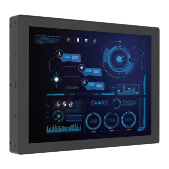
- Page 1 CO-W124C/M1101 Series User Manual Open Frame Monitor 24” TFT-LCD Full HD Open Frame Touch Monitor with Projected Capacitive Touch, 1x DisplayPort, 1x HDMI, 1x VGA Version: V1.00...
- Page 2 Contents Preface..............................4 Revision ............................4 Copyright Notice .......................... 4 Acknowledgement ........................4 Disclaimer ............................. 4 Declaration of Conformity ......................4 FCC ............................4 CE ............................5 Product Warranty Statement ....................... 5 Warranty ..........................5 RMA ............................5 Limitation of Liability ......................6 Technical Support and Assistance ....................
- Page 3 3.3 Installing Flat Mount ......................27 3.3.1 Fixing from front side ....................31 3.3.2 Fixing from rear side ....................31 3.4 Disassembling Mounting Brackets ..................33 3.5 Installing VESA Mount ......................34 3.6 Installing Optional Accessories .................... 35 3.6.1 URM01 ........................35 CO-W124C/M1101 | User Manual...
- Page 4 2024/11/11 Copyright Notice © 2024 by Cincoze Co., Ltd. All rights are reserved. No parts of this manual may be copied, modified, or reproduced in any form or by any means for commercial use without the prior written permission of Cincoze Co., Ltd. All information and specification provided in this manual are for reference only and remain subject to change without prior notice.
- Page 5 (such as a fuse, battery, etc.), are not warranted. Before sending your product in, you will need to fill in Cincoze RMA Request Form and obtain a RMA number from us. Our staff is available at any time to provide you with the most friendly and immediate service.
- Page 6 Limitation of Liability Cincoze’ liability arising out of the manufacture, sale, or supplying of the product and its use, whether based on warranty, contract, negligence, product liability, or otherwise, shall not exceed the original selling price of the product. The remedies provided herein are the customer’s sole and exclusive remedies.
- Page 7 Safety Precautions Before installing and using this device, please note the following precautions. Read these safety instructions carefully. Keep this User’s Manual for future reference. Disconnected this equipment from any AC outlet before cleaning. For plug-in equipment, the power outlet socket must be located near the equipment and must be easily accessible.
- Page 8 Package Contents Before installation, please ensure all the items listed in the following table are included in the package. Item Description Q’ty CO-W124C/M1101 Touch Monitor USB Cable VGA Cable Power Terminal Block Connector (Female) Screw Pack Note: Notify your sales representative if any of the above items are missing or damaged. Ordering Information Model No.
- Page 9 Chapter 1 Product Introductions CO-W124C/M1101 | User Manual...
- Page 10 1.1 Overview The Cincoze CO-100/M1101 series open frame industrial touch monitors include HDMI and DisplayPort digital inputs, and VGA analog input. The biggest highlight is its patented adjustable mounting bracket with thickness adjustment and locking types to make installation easier. The CO-100/M1101 is designed for equipment manufacturers and seamlessly integrates into control cabinets of various materials and thicknesses.
- Page 11 1.2 Specifications 1.2.1 CO-W124C/M1101 Model Name CO-W124C Display • 24” (16:9) LCD Size • 1920 x 1080 Resolution • 300 Brightness (cd/m2) • 5000:1 Contrast Ratio • 16.7M LCD Color • 0.27675(H) x 0.27675(V) Pixel Pitch (mm) • 178 (H) / 178 (V) Viewing Angle •...
- Page 12 • EN/IEC 61000-4-4 EFT: AC Power: 1 kV; DC Power: 0.5 kV; Signal: 0.5 kV • EN/IEC 61000-4-5 Surges: AC Power: 2 kV; Signal: 1 kV • EN/IEC 61000-4-6 CS: 3V • EN/IEC 61000-4-8 PFMF: 50 Hz, 1A/m • EN/IEC 61000-4-11 Voltage Dips & Voltage Interruptions: 0.5 cycles at 50 Hz Model Name M1101 Graphics...
- Page 13 • UL, cUL, CB, IEC, EN 62368-1 Safety * Product Specifications and features are for reference only and are subject to change without prior notice. For more information, please refer to the latest product datasheet from Cincoze's website. CO-W124C/M1101 | User Manual...
- Page 14 1.3 External Layout 1.3.1 Front 1.3.2 Rear 1.3.3 Left 1.3.4 Right CO-W124C/M1101 | User Manual...
- Page 15 1.4 Dimensions 1.4.1 CO-W124C/M1101 CO-W124C/M1101 | User Manual...
- Page 16 Chapter 2 Introduction to Switches and Connectors on Monitor Module CO-W124C/M1101 | User Manual...
- Page 17 2.1 Switches and Connectors Location 2.1.1 Rear Panel USB2.0 DC IN HDMI Audio-in Switches & Connector Definition DC IN DC +9V-48V Power Connector A standard 15-pin female VGA connector used to connect the monitor to the system graphics interface. Audio-in Used to connect an audio cable.
- Page 18 2.1.2 Right Panel Power LED Menu Standby LED Brightness Down LCD On/Off Auto Brightness Up Definition Switches & Connector OSD (On Screen Display) Function: Brightness Down Used to turn down the brightness on the screen display, or to decrease the value of selected item.
- Page 19 2.2 OSD Function Description OSD Menu Description • Backlight • Brightness • Contrast • Sharpness • Exit • Auto Adjust • H Position (Horizontal) • V Position (Vertical) • Clock • Phase • White Balance • Exit • Temperature • Color Effect •...
- Page 20 Base on LCD type information Exit the main menu * If using HDMI or DisplayPort connection, all options within the "Display" menu are unavailable. CO-W124C/M1101 | User Manual...
- Page 21 Chapter 3 System Setup CO-W124C/M1101 | User Manual...
- Page 22 3.1 Installing CDS Mount In order to prevent electric shock or system damage, must turn off power and disconnect the unit from power source before removing the chassis cover. (Afin d'éviter tout risque d'électrocution ou d'endommagement du système, vous devez couper l'alimentation et débrancher l'appareil de la source d'alimentation avant de retirer le couvercle du châssis.) This chapter takes the convertible monitor module (M1101) and display module (CO-W121C) for...
- Page 23 Step 4. Locate the female connector on the Convertible Monitor Module and then connect the modules. Step 5. Have the studs screwed to the display module through the holes of the Convertible Monitor Module. CO-W124C/M1101 | User Manual...
- Page 24 3.2 Installing Standard Mount The CO-100 series includes various mounting bracket designs, and this section demonstrates the CO-W124C installation process. Before starting the following steps, ensure the screws are secured in the default positions, as shown below. These positions are correct for Standard Mount, so no additional adjustments are necessary.
- Page 25 Step 1. Put the CO-100/M1101 module onto the rack’s back side. Step 2. Since there are two methods for fastening the CO-100/M1101 module onto the cabinet to complete the standard mount, choose the appropriate fastening method according to user’s preference. One is to fix the CO-100/M1101 module from the front side of the cabinet, which is illustrated in chapter 3.2.1.
- Page 26 3.2.2 Fixing from rear side 1. If the cabinet panel is with stud bolts as the following figure, user can prepare 16 pcs of nuts for fixing the module through the oblong holes (oblong hole size: 9mmx4mm, without screw thread). 2.
- Page 27 3.3 Installing Flat Mount The CO-100 series includes various mounting bracket designs, and this section demonstrates the CO-W124C installation process. Step 1. Loosen the screws marked with blue circles on all four sides of the module (Top, Bottom, Left, Right). Then, remove the positioning screws marked with red circles, as shown in the four images below.
- Page 28 Step 2. Measure the cabinet or rack thickness. The thickness is measured 3mm in this example. Step 3. Locate the top and bottom-side mounting brackets. Step 4. According to the thickness = 3mm for the example, push down the top and bottom-side mounting brackets to the place at screw hole = 3mm;...
- Page 29 Step 5. Fasten the three screws on the top and bottom-side mounting brackets. CO-W124C Top Side View CO-W124C Bottom Side View Step 6. Locate the left and right-side mounting brackets. Step 7. According to the thickness = 3mm for the example, push down the left and right-side mounting brackets to the place at screw hole = 3mm;...
- Page 30 CO-W124C Right Side View Step 8. Lift up the left and right-side mounting brackets with aligning the top and bottom-side mounting brackets, then fasten the three screws by the indicated sequence 1, 2, 3 on each side. CO-W124C Left Side View CO-W124C Right Side View Step 9.
- Page 31 Step 10. Since there are two methods for fastening the CO-100/M1101 module onto the cabinet to complete the standard mount, choose the appropriate fastening method according to user’s preference. One is to fix the CO-100/M1101 module from the front side of the cabinet, which is illustrated in chapter 3.3.1.
- Page 32 2. If the cabinet panel is with bosses as the following figures, user can prepare 16 pcs of M4 screws for fixing the module through the oblong holes (oblong hole size: 9mmx 4mm, without screw thread). CO-W124C/M1101 | User Manual...
- Page 33 3.4 Disassembling Mounting Brackets Step 1. Remove the 16 screws. Step 2. Remove the 3 screws on the left and right side of mounting brackets. Step 3. Remove the 3 screws on the top and bottom side of mounting brackets. Step 4.
- Page 34 3.5 Installing VESA Mount This chapter takes the convertible monitor module (M1101) and display module (CO-W121C) for demonstration purposes. The following picture indicates the VESA mounting hole pattern on the top side of M1101, which is compliant with the VESA mounting standard. Step 1.
- Page 35 3.6 Installing Optional Accessories 3.6.1 URM01 Before the installation of rack mount, user need to follow the previous chapter to disassemble the mounting brackets on the CO display module first. Step 1. Locate the screw holes on the PC or monitor module. Step 2.
- Page 36 Step 3. Assemble two rack mount brackets by fastening 4 screws (M5x6) at each side. Rack mount bracket holes for 19”~24” Panel PC series For P2002E For P2002/P1001E For M1101/P1001/P1101/ P1201/P1301/P2102/ P2102E/P2202/P2202E Left Right Bottom Step 4. Assemble two rack mount brackets by fastening 4 screws (M5x12), flat washers and hex nuts at each side.
- Page 37 © 2024 Cincoze Co., Ltd. All rights reserved. The Cincoze logo is a registered trademark of Cincoze Co., Ltd. All other logos appearing in this catalog are the intellectual property of the respective company, product, or organization associated with the logo.
Need help?
Do you have a question about the CO-W124C/M1101 Series and is the answer not in the manual?
Questions and answers