
Related Manuals for Cincoze CO-100/M1101 Series


Summary of Contents for Cincoze CO-100/M1101 Series
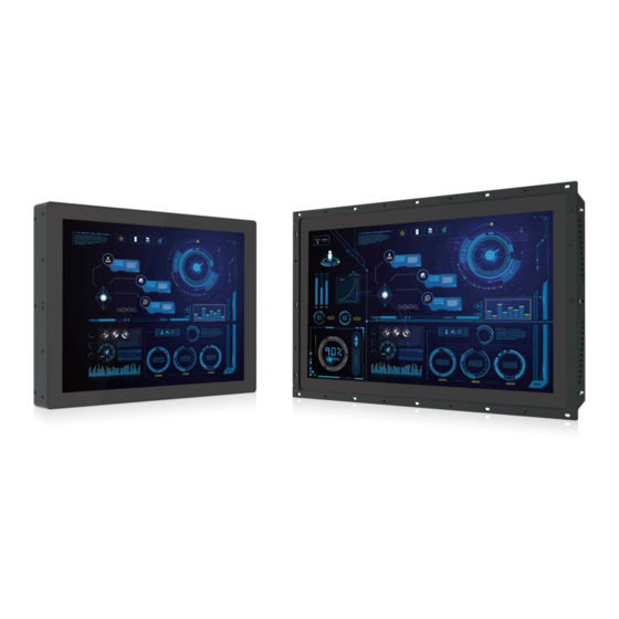
- Page 1 CO-100/M1101 Series User Manual Open Frame Monitor 21.5" TFT-LCD Full HD Open Frame Touch Monitor with Projected Capacitive Touch, 1x DisplayPort, 1x HDMI, 1x VGA Version: V1.00...
-
Page 2: Table Of Contents
Contents Preface..............................4 Revision ............................4 Copyright Notice .......................... 4 Acknowledgement ........................4 Disclaimer ............................. 4 Declaration of Conformity ......................4 FCC ............................4 CE ............................5 RU ............................5 Product Warranty Statement ....................... 5 Warranty ..........................5 RMA ............................5 Limitation of Liability ...................... - Page 3 3.2.2 Fixing from rear side ....................25 3.3 Installing Flat Mount ......................27 3.3.1 Fixing from front side ....................30 3.3.2 Fixing from rear side ....................31 3.4 Disassembling Mounting Brackets ..................32 3.5 Installing VESA Mount ......................33 3.6 Installing Optional Accessories .................... 34 3.6.1 URM01 ........................
-
Page 4: Preface
2023/09/04 Copyright Notice © 2023 by Cincoze Co., Ltd. All rights are reserved. No parts of this manual may be copied, modified, or reproduced in any form or by any means for commercial use without the prior written permission of Cincoze Co., Ltd. All information and specification provided in this manual are for reference only and remain subject to change without prior notice. -
Page 5: Product Warranty Statement
Before sending your product in, you will need to fill in Cincoze RMA Request Form and obtain a RMA number from us. Our staff is available at any time to provide you with the most friendly and immediate service. -
Page 6: Limitation Of Liability
Limitation of Liability Cincoze’ liability arising out of the manufacture, sale, or supplying of the product and its use, whether based on warranty, contract, negligence, product liability, or otherwise, shall not exceed the original selling price of the product. The remedies provided herein are the customer’s sole and exclusive remedies. -
Page 7: Safety Precautions
This indication alerts operators to an operation that, if not strictly observed, may result in safety hazards to personnel or damage to equipment. (Cette indication avertit les opérateurs d'une opération qui, si elle n'est pas strictement observée, peut entraîner des risques pour la sécurité du personnel ou des dommages à l'équipement.) This indication provides additional information to complete a task easily. -
Page 8: Package Contents
9-48 VDC, minimum 5-1A, with minimum rated maximum ambient temperature 70°C, and has to be evaluated according to UL/IEC/EN 60950-1 and/or UL/IEC/EN 62368-1. If need further assistance, please contact Cincoze for further information. 17. Ensure to connect the power cord of power adapter to a socket-outlet with earthing connection. -
Page 9: Chapter 1 Product Introductions
Chapter 1 Product Introductions CO-100/M1101 | User Manual... -
Page 10: Overview
1.1 Overview The Cincoze CO-100/M1101 series open frame industrial touch monitors include HDMI and DisplayPort digital inputs, and VGA analog input. The biggest highlight is its patented adjustable mounting bracket with thickness adjustment and locking types to make installation easier. The CO-100/M1101 is designed for equipment manufacturers and seamlessly integrates into control cabinets of various materials and thicknesses. -
Page 11: Specifications
1.2 Specifications 1.2.1 CO-W121C/M1101 The table on this page refers to the specifications of CO-W121C alone. Model Name CO-W121C Display • 21.5” (16:9) LCD Size • 1920 x 1080 Resolution • 300 cd/m2 Brightness • 5000:1 Contract Ratio • 16.7M LCD Color •... - Page 12 The table below refers to the specifications of M1101 alone. Model Name M1101 Graphics • 1x HDMI Connector (1920 x 1080 @60Hz) HDMI-in • 1x DisplayPort Connector (1920 x 1080 @60Hz) DP-in • 1x VGA Connector (1920 x 1080 @60Hz) VGA-in Audio •...
- Page 13 • UL, cUL, CB, IEC, EN 62368-1 Safety * Product Specifications and features are for reference only and are subject to change without prior notice. For more information, please refer to the latest product datasheet from Cincoze's website. CO-100/M1101 | User Manual...
-
Page 14: External Layout
1.3 External Layout 1.3.1 Front 1.3.2 Rear 1.3.3 Left 1.3.4 Right CO-100/M1101 | User Manual... -
Page 15: Dimensions
1.4 Dimensions 1.4.1 CO-W121C/M1101 CO-100/M1101 | User Manual... -
Page 16: Chapter 2 Introduction To Switches And Connectors On Monitor Module
Chapter 2 Introduction to Switches and Connectors on Monitor Module CO-100/M1101 | User Manual... -
Page 17: Switches And Connectors Location
2.1 Switches and Connectors Location 2.1.1 Rear Panel USB2.0 DC IN HDMI Audio-in Switches & Connector Definition DC IN DC +9V-48V Power Connector A standard 15-pin female VGA connector used to connect the monitor to the system graphics interface. Audio-in Used to connect an audio cable. -
Page 18: Right Panel
2.1.2 Right Panel Power LED Menu Standby LED Brightness Down LCD On/Off Auto Brightness Up Definition Switches & Connector OSD (On Screen Display) Function: Brightness Down Used to turn down the brightness on the screen display, or to decrease the value of selected item. -
Page 19: Osd Function Description
2.2 OSD Function Description OSD Menu Description • Backlight • Brightness • Contrast • Sharpness • Exit • Auto Adjust • H Position (Horizontal) • V Position (Vertical) • Clock • Phase • White Balance • Exit • Temperature • Color Effect •... - Page 20 Base on LCD type information Exit the main menu * If using HDMI or DisplayPort connection, all options within the "Display" menu are unavailable. CO-100/M1101 | User Manual...
-
Page 21: Chapter 3 System Setup
Chapter 3 System Setup CO-100/M1101 | User Manual... -
Page 22: Installing Cds Mount
3.1 Installing CDS Mount In order to prevent electric shock or system damage, must turn off power and disconnect the unit from power source before removing the chassis cover. (Afin d'éviter tout risque d'électrocution ou d'endommagement du système, vous devez couper l'alimentation et débrancher l'appareil de la source d'alimentation avant de retirer le couvercle du châssis.) This chapter takes the convertible monitor module (M1101) and display module (CO-W121C) for... - Page 23 Step 4. Locate the female connector on the Convertible Monitor Module and then connect the modules. Step 5. Have the studs screwed to the display module through the holes of the Convertible Monitor Module. CO-100/M1101 | User Manual...
-
Page 24: Installing Standard Mount
3.2 Installing Standard Mount Before doing the following steps, please make sure the screw positions are fastened at the default positions as indicated in the following picture. The default positions are the correct positions for Standard Mount, so it does not need to change the screw positions additionally for Standard Mount. -
Page 25: Fixing From Front Side
3.2.1 Fixing from front side 1. Fasten the screws from the cabinet’s front side. Please prepare 12 pcs of M4 screws for fixing the module through the circle holes (with screw thread). 3.2.2 Fixing from rear side 1. If the cabinet panel is with stud bolts as the following figure, user can prepare 16 pcs of nuts for fixing the module through the oblong holes (oblong hole size: 9mmx4mm, without screw thread). - Page 26 2. If the cabinet panel is with bosses as the following figures, user can prepare 16 pcs of M4 screws for fixing the module through the oblong holes (oblong hole size: 9mmx 4mm, without screw thread). CO-100/M1101 | User Manual...
-
Page 27: Installing Flat Mount
3.3 Installing Flat Mount Step 1. Locate the left and right-side mounting brackets. Step 2. Remove the two screws on the left and right-side mounting brackets. Step 3. Loosen the three screws on the left and right-side mounting brackets. Step 4. Measure the rack thickness. The thickness is measured 3mm in this example. CO-100/M1101 | User Manual... - Page 28 Step 5. According to the thickness = 3mm for the example, push down the left and right-side mounting brackets to the place at screw hole = 3mm. Step 6. Fasten the two screws on the left and right-side mounting brackets. Step 7.
- Page 29 Step 9. Remove the two screws on the top and bottom-side mounting brackets. Step 10. Loosen the three screws on the top and bottom-side mounting brackets. Step 11. According to the thickness = 3mm for the example, push down the top and bottom-side mounting brackets to the place at screw hole = 3mm.
-
Page 30: Fixing From Front Side
Step 14. Put the CO-100/M1101 module onto the rack back side. Step 15. Since there are two methods for fastening the CO-100/M1101 module onto the cabinet to complete the standard mount, choose the appropriate fastening method according to user’s preference. One is to fix the CO-100/M1101 module from the front side of the cabinet, which is illustrated in chapter 3.3.1. -
Page 31: Fixing From Rear Side
3.3.2 Fixing from rear side 1. If the cabinet panel is with stud bolts as the following figure, user can prepare 16 pcs of nuts for fixing the module through the oblong holes (oblong hole size: 9mmx4mm, without screw thread). 2. -
Page 32: Disassembling Mounting Brackets
3.4 Disassembling Mounting Brackets Before the installation of VESA mount and rack mount, user need to disassemble the mounting brackets on the CO display module first. Step 1. Remove the 8 screws. Step 2. Remove the 3 screws on the left and right side of mounting brackets. Step 3. -
Page 33: Installing Vesa Mount
3.5 Installing VESA Mount This chapter takes the convertible monitor module (M1101) and display module (CO-W121C) for demonstration purposes. The following picture indicates the VESA mounting hole pattern on the top side of M1101, which is compliant with the VESA mounting standard. Step 1. -
Page 34: Installing Optional Accessories
3.6 Installing Optional Accessories 3.6.1 URM01 Before the installation of rack mount, user need to follow the previous chapter to disassemble the mounting brackets on the CO display module first. Step 1. Locate the screw holes on the PC or monitor module. Step 2. - Page 35 Step 3. Assemble two rack mount brackets by fastening 4 screws (M5x6) at each side. Rack mount bracket holes for 21” Panel PC series For P2002E For P2002/P1001E For M1101/P1001/P1101/ P1201/P2102/ P2102E Left Right Bottom Step 4. Assemble two rack mount brackets by fastening 4 screws (M5x12), flat washers and hex nuts at each side.
- Page 36 © 2023 Cincoze Co., Ltd. All rights reserved. The Cincoze logo is a registered trademark of Cincoze Co., Ltd. All other logos appearing in this catalog are the intellectual property of the respective company, product, or organization associated with the logo.
Need help?
Do you have a question about the CO-100/M1101 Series and is the answer not in the manual?
Questions and answers