Advertisement
Quick Links
3120182 EFV 20240425
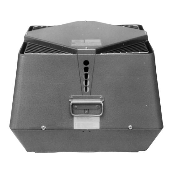
EFV fan
READ AND SAVE THESE INSTRUCTIONS!
Product information
Mechanical installation
Electrical installation
Start up and configuration
Maintenance and troubleshooting
Job name: _________________________________
Installer: __________________________________
Installation date: ___________________________
Distributor contact information:
ENERVEX Inc. • T: 800.255.2923
info@enervex.com • www.enervex.com
Installation and operation manual
Chapters 1 + 2
Chapter 3
Chapter 4
Chapter 5
Chapter 6
USA
CAN
Advertisement

Related Manuals for Exodraft EFV


Summary of Contents for Exodraft EFV
- Page 1 Installation and operation manual 3120182 EFV 20240425 EFV fan READ AND SAVE THESE INSTRUCTIONS! Product information Chapters 1 + 2 Mechanical installation Chapter 3 Electrical installation Chapter 4 Start up and configuration Chapter 5 Maintenance and troubleshooting Chapter 6 Job name: _________________________________...
- Page 2 4.2 Wiring diagram for EFV 250-450 ........
- Page 3 It can also be used to increase the capacity and efficiency of such a system. Code Compliance The fan housing is made of heavy cast aluminum and can be opened for easy cleaning. The EFV 250- 450 have an backward inclined impeller constructed of aluminum with permanently attached balanc- ing weights.
- Page 4 3120182 EFV 20240425 1.3 Shipping The fan is shipped in a corrugated cardboard box. A transport securing device may be attached to the bottom of the fan to hold the motor and impeller in place. Do not remove the device until the fan is at the installation point.
- Page 5 10 feet and a minimum of 4 feet away from any door or window. For complete information, consult ENERVEX or your local building codes. 3.1 Transport safety device Before mounting the exodraft fan make sure the transport safety brackets have been removed (EFV315, 400 and 450 only). Fig. 3 3.2 Single fan on steel chimney...
- Page 6 3120182 EFV 20240425 3.4 Single fan on brick chimney The installation procedure is the same for round and square flues. If a clay flue liner is installed and extends beyond the chimney, cut it back so it extends no more than 1/2 inch above the chimney crown.
- Page 7 3120182 EFV 20240425 3.6 Multiple fan installations It is possible to install multiple fans in parallel. For details, please contact ENERVEX. The fans must be placed so they can be opened for maintenance and chimney access. Fig. 8 shows optimal placement.
- Page 8 3120182 EFV 20240425 4. Electrical installation 4.1 Electrical requirements Power requirements depend on the fan size and they can be found on page 4. DANGER Turn off electrical power before servicing. Contact with live electric components can cause shock or death.
- Page 9 3120182 EFV 20240425 4.2 Wiring diagram for EFV 250-450 The wiring diagrams below shows a three-phase fan connected to the power source (see fig. 10). Use a 3-conductor wire of minimum 15 AWG with ground. Wiring must be run outside the chimney/stack in flexible or rigid metal conduit.
- Page 10 Apply power and check that the axial vane or impeller is rotating in the direction of the arrow on the side of the top motor cover. All exodraft fans run in a clockwise direction when viewed from the top. White Black Switching any two phases in the junction box will reverse the rotation.
- Page 11 6. Maintenance and troubleshooting 6.1 Maintenance intervals The exodraft fan is designed for continuous use. For gas applications, no regular maintenance is required. For oil applications, inspect the axial vane or impeller after 3 months and set up a periodic inspection based on these findings.
- Page 12 Distributor in USA & Canada P: 770.587.3238 ENERVEX Inc. F: 770.587.4731 1685 Bluegrass Lake Parkway T: 800.255.2923 Alpharetta info@enervex.com GA 30004 www.enervex.com www.exodraft.com...
Need help?
Do you have a question about the EFV and is the answer not in the manual?
Questions and answers