
Related Manuals for EMPERO EM.01.P


Summary of Contents for EMPERO EM.01.P
-
Page 1: Table Of Contents
MEAT MINCERS CONTENTS GENERAL INFORMATION Page PRODUCT DESCRIPTION Page TECHNICAL INFORMATION Page TRANSPORTATION Page UNPACKING Page INSTALLATION Page SAFETY INSTRUCTIONS Page OPERATION Page CLEANING & MAINTENANCE Page TROUBLESHOOTING Page SPARE PART LIST- EXPLODING DRAWING Page ELECTRIC CIRCUIT SCHEMA Page... -
Page 2: Ageneral Information
MEAT MINCERS GENERAL INFORMATION Before installing the appliance, read operation and maintenance instructions carefully.Wrong installation and part changing may damage the product or may cause injury on people.These are not in our company’s responsibility to damage the appliance intentionally,negligence,detriments because of disobeying instructions and regulations,wrong connections.Unauthorized intervention to appliance invalidates the warranty. -
Page 3: A1 Product Description
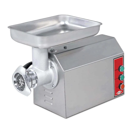
MEAT MINCERS PRODUCT DESCRIPTION *The Professional Meat Mincers,that provides high efficiency has been designed to be used in industrial kitchens. Product Code Dimensions (mm) Weight (kg) Packaging Dimensions (mm) EM.01.P 360x800x410 375x815x430 EM.02.P 360x800x410 375x815x430 EM.09.P 320x770x405 335x785x425 EM.10.P 320x770x405 335x785x425 EM.22.09... -
Page 4: A2 Technical Information
MEAT MINCERS TECHNICAL INFORMATION Operating Capacity Power Cable Fuse Product Code Voltage (mm²) (kg/h) (Kw) EM.01.P 3x2,5 EM.02.P 4x1,5 EM.09.P 3x2,5 EM.10.P 4x1,5 EM.22.09 3x2,5 EM.22.10 4x1,5 EM.32.09 3x2,5 EM.32.10 4x1,5 EMP.12.01.P 0,55 3x1,5 EMP.12.02.P 0,55 5x1,5 EMP.22.01.P 0,75 3x1,5 EMP.22.02.P... -
Page 5: Binstallation
MEAT MINCERS INSTALLATION *Please place the product to straight and sturdy ground,please take necessary steps against possibility of overturn. *Technician who will serve for installation and service for the appliance must be professional on this subject and must have installation and service licenses by the company. *Connection to Electric Power Supply must be done by authorized person. -
Page 6: Doperation
OPERATION *Control Panel; A : Urgent stop button B : Start button C : Stop button D : Operation to forward-back EM.01.P-02.P-09.P-10.P *Operating; Before operating,clean the spiral,disk,blade and inside of meat tube with a hot water and dry. ... - Page 7 MEAT MINCERS * Control Panel: A : Start button B : Stop button C : Operation to back D : Operation to forward E : Urgent stop button EM.22.09-10 / EM.32.09-10 * Operating: Before operating,clean the spiral,disk,blade and inside of meat tube with a hot water and dry.
- Page 8 MEAT MINCERS OPERATION *Control Panel; A : Operation to forward B : Operation to back C : Stop EMP.12.01.P-12.02.P-22.01.P-22.02.P *Operating; Before operating,clean the spiral,disk,blade and inside of meat tube with a hot water and dry. Switch forward to operate the appliance. ...
-
Page 9: Ecleaning & Maintenance
MEAT MINCERS CLEANING & MAINTENANCE CLEANING AND MAINTENANCE AFTER EVERY USE Clean the meat tube,spiral,disk and blade after every meat mincing process. Clean the outer surface of appliance with a wet cloth and then dry. Always turn off the appliance and disconnect from the power supply before cleaning. ... -
Page 10: Ftroubleshooting
MEAT MINCERS TROUBLESHOOTING Check if the appliance is plugged in. THE APPLIANCE DOESN’T OPERATE Check the electrical connections and voltage. Check the urgent stop button. There may remain bone pieces in the meat.In thıs situation stop the appliance THE APPLIANCE IS NOISY check the meat and blade. -
Page 11: Gspare Part List-Exploding Drawing
MEAT MINCERS SPARE PART LIST-EXPLODING DRAWING EM.01.P / EM.02.P... - Page 12 MEAT MINCERS SPARE PART LIST-EXPLODING DRAWING PRODUCT CODE : EM.01 / EM.02 PRODUCT NAME P.CODE ELECTRICAL PANEL GROUP M.ELK-PNO-ETM-005 EMERGENCY STOP BUTTON M.ELK-SLT-BTL-003 START STOP BUTTON ERS.M.ELK-SLT-BTL-003 1-0-2 SWITCH M.ELK-SLT-PKO-010 PG-11 CABLE FITTING ERS.M.ELK-RKR-PLS-003 3*2.5 MM CABLE HEL-KB-TT-3*2,5-SYH IGNITION M.ELK-SLT-KON-001 CONTACTOR LC1K0910M ERS.M.ELK-KNT-KNT-021 FOOT...
- Page 13 MEAT MINCERS SPARE PART LIST-EXPLODING DRAWING EM.09.P / EM.10.P...
- Page 14 MEAT MINCERS SPARE PART LIST-EXPLODING DRAWING PRODUCT CODE : EM.09.P / EM.10.P PRODUCT NAME P.CODE ELECTRICAL PANEL GROUP : EM.09.P M.ELK-PNO-ETM-005 ELECTRICAL PANEL GROUP EM.10.P M.ELK-SLT-KON-001 CONTACTOR LC1K0910M ERS.M.ELK-KNT-KNT-021 EMERGENCY STOP BUTTON M.ELK-SLT-BTL-003 START STOP BUTTON ERS.M.ELK-SLT-BTL-003 1-0-2 SWITCH M.ELK-SLT-PKO-010 PG-11 CABLE FITTING ERS.M.ELK-RKR-PLS-003 3*1,5 CABLE...
- Page 15 MEAT MINCERS SPARE PART LIST-EXPLODING DRAWING EM.22.09 / EM.22.10...
- Page 16 MEAT MINCERS SPARE PART LIST-EXPLODING DRAWING PRODUCT CODE: EM.22.09 / EM.22.10 PRODUCT NAME P.CODE FOOT M.AKS-AYK-PLS-007 ELECTRICAL PANEL GROUP 22.09 M.ELK-PNO-ETM-009 – EM.22.09 ELECTRICAL PANEL GROUP 22.10 M.ELK-PNO-ETM-007 EMERGENCY STOP BUTTON M.ELK-SLT-BTL-003 GREEN DIRECTION BUTTON M.ELK-SLT-BTL-008 START STOP BUTTON ERS.M.ELK-SLT-BTL-003 PG-13,5 CABLE FITTING M.ELK-RKR-PLS-007 3*1,5 CABLE 22.09...
- Page 17 MEAT MINCERS SPARE PART LIST-EXPLODING DRAWING EM.32.09 / EM.32.10...
- Page 18 MEAT MINCERS SPARE PART LIST-EXPLODING DRAWING PRODUCT CODE : EM.32.09 / EM.32.10 PRODUCT NAME P.CODE ELECTRICAL PANEL GROUP M.ELK-PNO-ETM-009 EMERGENCY STOP BUTTON 32.09 M.ELK-SLT-BTL-003 EMERGENCY STOP BUTTON 32.10 M.ELK-SLT-BTL-003 GREEN DIRECTION BUTTON ERS.M.ELK-SLT-BTL-003 START STOP BUTTON M.ELK-RKR-PLS-007 PG-13,5 CABLE FITTING HEL-KB-TT-3*2,5-SYH 3*2.5 MM CABLE 32.09 M.ELK-SLT-BTL-008...
- Page 19 MEAT MINCERS SPARE PART LIST-EXPLODING DRAWING PRODUCT CODE: EMP.12.01.P / EMP.12.02.P PRODUCT NAME P.CODE ELECTRICAL PANEL GROUP 12.01 M.ELK-PNO-ETM-001 ELECTRICAL PANEL GROUP 12.02 M.ELK-PNO-ETM-002 IGNITION M.ELK-KNT-KNT-025 CONTACTOR LC1K0910M ERS.M.ELK-KNT-KNT-021 EMERGENCY STOP BUTTON M.ELK-SLT-BTL-003 STOP BUTTON M.ELK-SLT-BTL-006 3*1,5 CABLE M.ELK-PWR-PBK-003 IGNITION 12.01 M.ELK-KNT-KNT-025 IGNITION 12.02 HEL-KB-TT-5*1,5-001...
- Page 20 MEAT MINCERS RING 472-40 B-SEG-SYH-009 RING 471-15 B-SEG-SYH-002 BEARING ( 6203 ZZ ) M.RLM-NRM-010 SLEEVE SHAFT YTL-ERS.ETM-KS-0021 OIL PLUG YTL-ERS.ETM-KS-0022 ENGINE (ENGINE) GEAR M.MON-DSL-001 SLEEVE GEAR YDK-ERS.ETM-CN-0023 SHAFT SHAFT YTL-ERS.ETM-KS-0020 TRANSMISSION M.ENJ-ERS-PLS-ETM-001 SPIRAL M.MON-ET-003 SPIRAL SCREW YTL-ERS.ETM-KS-0018 12 MIRROR M.BCK-ETM-006 SHAFT GEAR M.MON-DSL-002 ELBOW CASTING...
- Page 21 MEAT MINCERS SPARE PART LIST-EXPLODING DRAWING PRODUCT CODE: EMP.22.01.P / EMP.22.02.P PRODUCT NAME P.CODE ELECTRICAL PANEL GROUP 22.01 M.ELK-PNO-ETM-001 ELECTRICAL PANEL GROUP 22.02 M.ELK-PNO-ETM-002 CONTACTOR LC1K0910M ERS.M.ELK-KNT-KNT-021 EMERGENCY STOP BUTTON M.ELK-SLT-BTL-003 IGNITION M.ELK-KNT-KNT-025 STOP BUTTON M.ELK-SLT-BTL-006 PG-11 CABLE FITTING ERS.M.ELK-RKR-PLS-003 3*1,5 CABLE M.ELK-PWR-PBK-003 CONTACTOR LC1K0910M 22.01...
-
Page 22: Helectric Circuit Schema
MEAT MINCERS ELECTRIC CIRCUIT SCHEMA A1 - PHASE SWITCHOVER RIGHT LEFT SWITCH B1 - STOP BUTTON B2 - START BUTTON C1 - CONTACTOR L1 - START SIGNAL LAMP M - ENGINE EM.01.P – EM.09.P... - Page 23 MEAT MINCERS ELECTRIC CIRCUIT SCHEMA EM.02.P – EM.10.P A1 - PHASE SWITCHOVER RIGHT LEFT SWITCH B1 - STOP BUTTON B2 - START BUTTON C1 - CONTACTOR L1 - START SIGNAL LAMP M - ENGINE...
- Page 24 MEAT MINCERS ELECTRIC CIRCUIT SCHEMA B1-STOP BUTTON B2-START BUTTON B3-RIGHT START BUTTON B4-LEFT START BUTTON C1-SEALING CONTACTOR C2-ENGINE RIGHT DIRECTION CONTACTOR C3-ENGINE LEFT DIRECTION CONTACTOR CTR-CONDENSER FN-COOLING FAN L1-START LAMP L2-RIGHT-LEFT START LAMP M-ENGINE EM.22.09 / EM.32.09...
- Page 25 MEAT MINCERS ELECTRIC CIRCUIT SCHEMA B1-STOP BUTTON B2-START BUTTON B3-RIGHT START BUTTON B4-LEFT START BUTTON C1-SEALING CONTACTOR C2-ENGINE RIGHT DIRECTION CONTACTOR C3-ENGINE LEFT DIRECTION CONTACTOR CTR-CONDENSER FN-COOLING FAN L1-START LAMP L2-RIGHT-LEFT START LAMP M-ENGINE EM.22.10 / EM.32.10...
-
Page 26: Product Code
MEAT MINCERS ELECTRIC CIRCUIT SCHEMA PRODUCT CODE POWER (KW) VOLTAGE EMP.12.01.P 0,55 1400 EMP.22.01.P 0,75 1400 START1 START2 Motor Right Motor Right Motor Left 0,55 Right Left Lft Start Terminal Start Direction Direction Start Start Button Button Contactor Contactor 1400 Lamp Lamp... - Page 27 MEAT MINCERS ELECTRIC CIRCUIT SCHEMA PRODUCT CODE POWER (KW) VOLTAGE EMP.12.02.P 0,55 1400 EMP.22.02.P 0,75 1400 START1 START2 Motor Right Motor Right Motor Left 0,55 Right Left Left Start Terminal Start Direction Direction Start Start Button Button Contactor Contactor 1400 Lamp Lamp...
Need help?
Do you have a question about the EM.01.P and is the answer not in the manual?
Questions and answers