Advertisement
Quick Links
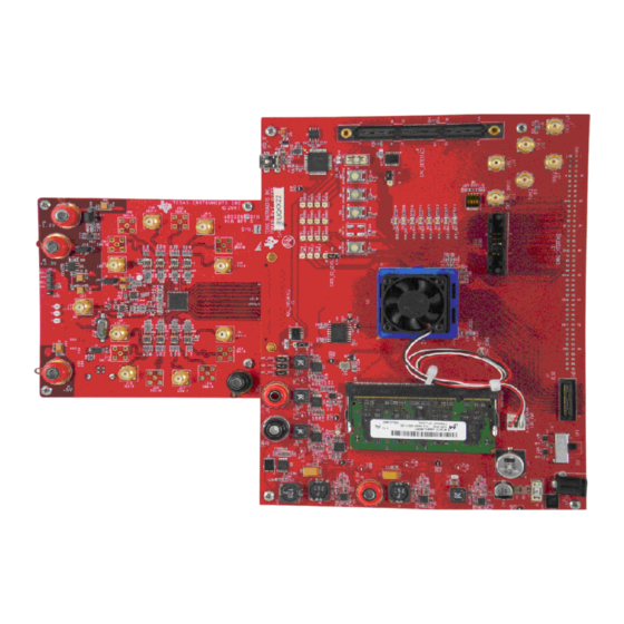
TSW140x High Speed Data Capture/Pattern Generator
The Texas Instruments TSW1400 Evaluation Module (EVM) is a next generation of pattern generator and
data capture card used to evaluate performances of a wide range of Texas Instruments (TI) high-speed
analog-to-digital converters (ADC) and digital-to-analog converters (DAC). For an ADC, capturing the
sampled data over an LVDS interface when using a high-quality, low-jitter clock, and a high-quality input
frequency, the TSW1400 can be used to demonstrate data sheet performance specifications. Together
with the accompanying Labview based Graphic User Interface (GUI), it is a complete system that captures
and evaluates data samples from ADC EVM's and generates and sends desired test patterns to DAC
EVM's
The TSW1405 is a low cost data capture card with limited capabilities as compared with the TSW1400.
The TSW1405 supports pattern capture for most LVDS format TI ADC EVMs, but with a capture buffer
limitation of 64K samples. The TSW1405 draws its power from the USB connection to the PC for easy
setup and operation. The same TSW1400 Graphical User Interface supports the TSW1405 as well,
making for a consistent feel across the different platforms.
The TSW1406 is a low cost pattern generator card with limited capabilities as compared with the
TSW1400. The TSW1406 supports pattern generation for most LVDS format TI DAC EVMs, but with a
pattern limitation of 64K samples. The TSW1406 draws its power from the USB connection to the PC for
easy setup and operation. The same TSW1400 GUI supports the TSW1406 as well.
TSW1400
TSW1405
TSW1406
1
Functionality
1.1
ADC EVM Data Capture
1.2
DAC EVM Pattern Generator
2
Hardware Configuration
2.1
Power Connections
2.2
Switches, Jumpers and Fuses
2.3
LED's
2.4
Connectors
3
Software Start up
3.1
Installation Instructions
3.2
USB Interface and Drivers
3.3
Device ini Files
4
User Interface
4.1
Toolbar
4.2
Status Windows
All trademarks are the property of their respective owners.
SLWU079 – February 2012
Submit Documentation Feedback
Table 1. TSW140x EVM Features
I/O Interface
LVDS
CMOS
Future
Yes
Firmware
Release
Yes
No
Yes
No
.................................................................................................................
..........................................................................................
.....................................................................................
....................................................................................................
................................................................................................
...................................................................................
................................................................................................................
..........................................................................................................
...........................................................................................................
............................................................................................
........................................................................................
....................................................................................................
..............................................................................................................
.............................................................................................................
...................................................................................................
Copyright © 2012, Texas Instruments Incorporated
JESD
16 Bit Memory Depth
Future
Firmware
512M
Release
No
64K
No
64K
Contents
TSW140x High Speed Data Capture/Pattern Generator Card
User's Guide
SLWU079 – February 2012
Card
Data Capture
Data Source
Yes
Yes
Yes
No
No
Yes
10
10
11
14
3
4
4
4
5
5
6
6
7
7
8
1
Advertisement


Need help?
Do you have a question about the TSW140 Series and is the answer not in the manual?
Questions and answers