Table of Contents
Advertisement
Quick Links
TSW6011EVM
This document outlines the basic steps and functions that are required for the proper operation of the
TSW6011 evaluation module (EVM) system. The
used to demonstrate a
octal analog-to-digital converter (ADC). This guide helps the user to evaluate the performance of various
modes of operation of the TSW6011EVM. Throughout this document, the term evaluation module and the
abbreviation EVM are synonymous with the TSW6011EVM.
......................................................................................................................
1
1.1
1.2
1.3
2
2.1
3
3.1
3.2
4
4.1
4.2
4.3
4.4
5
5.1
5.2
Register 2
5.3
5.4
.......................................................................................................................
1
2
3
4
5
6
7
8
9
10
All trademarks are the property of their respective owners.
SLWU070D - February 2010 - Revised August 2016
Submit Documentation Feedback
TRF371125
integrated direct downconversion receiver interfacing to an
....................................................................................
...............................................................................
.........................................................................................................
.............................................................................................
.....................................................................................................
.....................................................................................................
...........................................................................................................
...............................................................................................................
............................................................................................................
.......................................................................................................
.................................................................................................
.................................................................................................
...........................................................................................
..........................................................................................................
..........................................................................................................
..........................................................................................................
..........................................................................................................
...................................................................................
.................................................................................
...........................................................................................
...............................................................................
..................................................................................................
....................................................................................................
..................................................................................................
.......................................................................................
.........................................................................................
Copyright © 2010-2016, Texas Instruments Incorporated
SLWU070D - February 2010 - Revised August 2016
TSW6011EVM
is a single RX channel board that can be
Contents
..........................................................................
List of Figures
.......................................................
Quick Start Guide
ADS5282
2
2
2
3
5
5
5
5
5
6
6
7
8
9
13
13
13
13
13
14
3
4
7
8
8
9
10
10
11
12
1
TSW6011EVM
Advertisement
Table of Contents

Subscribe to Our Youtube Channel
Related Manuals for Texas Instruments TSW6011EVM


Summary of Contents for Texas Instruments TSW6011EVM
-
Page 1: Table Of Contents
ADS5282 octal analog-to-digital converter (ADC). This guide helps the user to evaluate the performance of various modes of operation of the TSW6011EVM. Throughout this document, the term evaluation module and the abbreviation EVM are synonymous with the TSW6011EVM. Contents ........................ -
Page 2: Overview
Overview The TSW6011EVM board provides options to send an input RF signal directly to the TR371125 or through one or two low-noise amplifiers (LNAs) by moving two resistors. Additionally, there is an option to drive two of the ADCs with an external source. This source can be single-ended (board default through a transformer) or a differential signal (from a TRF3711xxEVM, for example). -
Page 3: Digital Processing Block Functions
TPS70445 I_EXT Q_EXT Figure 1. TSW6011EVM System Block Diagram Digital Processing Block Functions The FPGA receives the digital data from the ADC and converts it from serial to parallel format. The data then are split into two paths. One path converts the data back to unsigned serial data and determines which ADC output to route to the LVDS connector. -
Page 4: Fpga Digital Processing Block Diagram
Overview www.ti.com The FPGA digital processing block diagram is shown in Figure Figure 2. FPGA Digital Processing Block Diagram TSW6011EVM SLWU070D – February 2010 – Revised August 2016 Submit Documentation Feedback Copyright © 2010–2016, Texas Instruments Incorporated... -
Page 5: Software Installation
Software Installation www.ti.com Software Installation Installation Instructions Step 1. Download and install TSW6011EVM GUI Installer and MCRinstaller.exe on the web (www.ti.com/tool/tsw6011evm) Step 2. To get started the GUI, double-click TSW6011_control_panel.exe in your target directory. You can set this directory during installation. -
Page 6: Board Bring Up
– Follow the on-screen instructions to install the USB drivers. – If needed, the USB drivers can be accessed in the following directory: C:\TSW6011GUI\FTD245_Drivers\ TSW6011EVM SLWU070D – February 2010 – Revised August 2016 Submit Documentation Feedback Copyright © 2010–2016, Texas Instruments Incorporated... -
Page 7: Basic Rf Test
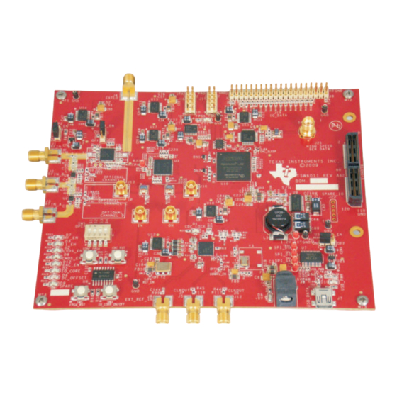
Set sweep time to 2.5 ms • Set RBW to 300 kHz • Set VBW to 1 MHz Figure 3. TSW6011EVM Board Top View SLWU070D – February 2010 – Revised August 2016 TSW6011EVM Submit Documentation Feedback Copyright © 2010–2016, Texas Instruments Incorporated... -
Page 8: Software Operation
I_EXT Q_EXT Figure 4. TSW6011EVM Software GUI Front Panel To enable the GUI, the user must click on the button labeled Connect in the upper left-hand corner. If communication between the GUI and TSW6011 is successful, the button changes to display Disconnect. -
Page 9: Device Initialization
To issue a device reset, click on the Reset ADC button. • Click on the X in the upper right-hand corner to close the panel. SLWU070D – February 2010 – Revised August 2016 TSW6011EVM Submit Documentation Feedback Copyright © 2010–2016, Texas Instruments Incorporated... -
Page 10: Tr371125 Control Panel
Click the Filter Bypass checkbox to bypass the TR371125 LPF internal filter. After loading the TRF371125, the output spectrum now looks as shown in Figure Figure 8. Test Tone From DAC5672 Output TSW6011EVM SLWU070D – February 2010 – Revised August 2016 Submit Documentation Feedback Copyright © 2010–2016, Texas Instruments Incorporated... -
Page 11: Digital Processing Control Panel
CDC Ext Ref: Disabled. Currently not used. IQ Correction Enable: When selected, IQ Correction is enabled. When disabled, IQ Correction block is bypassed. SLWU070D – February 2010 – Revised August 2016 TSW6011EVM Submit Documentation Feedback Copyright © 2010–2016, Texas Instruments Incorporated... -
Page 12: Test Tone After Iq Correction And Dc Offset Compensation
DAC5672. Contact TI if settings other than the default are required for the CDCE62005. TSW6011EVM SLWU070D – February 2010 – Revised August 2016 Submit Documentation Feedback Copyright © 2010–2016, Texas Instruments Incorporated... -
Page 13: Tr371125 Register Definitions
No adjustment of this register required The hex values in the Register # boxes are the actual values loaded into the TRF371125. SLWU070D – February 2010 – Revised August 2016 TSW6011EVM Submit Documentation Feedback Copyright © 2010–2016, Texas Instruments Incorporated... - Page 14 LVDS outputs. Mates with TSW1400 LVDS input connector. CMOS output data. Test connector. +6-VDC input power connector. USB connector. FPGA JTAG connector. FPGA PROM programming connector. SLWU070D – February 2010 – Revised August 2016 Submit Documentation Feedback Copyright © 2010–2016, Texas Instruments Incorporated...
- Page 15 Spare dip switches. Currently not used. Turn I/Q correction on/off. Currently not used Not Used FPGA Reset. Reset all FPGA registers. CDC Reset SLWU070D – February 2010 – Revised August 2016 Submit Documentation Feedback Copyright © 2010–2016, Texas Instruments Incorporated...
- Page 16 Changed From: "Plug one end of the provided +6-VDC power supply" To: "Plug +6-VDC power supply" in the list in ..........................Section 4.1 Revision History SLWU070D – February 2010 – Revised August 2016 Submit Documentation Feedback Copyright © 2010–2016, Texas Instruments Incorporated...
- Page 17 STANDARD TERMS AND CONDITIONS FOR EVALUATION MODULES Delivery: TI delivers TI evaluation boards, kits, or modules, including any accompanying demonstration software, components, or documentation (collectively, an “EVM” or “EVMs”) to the User (“User”) in accordance with the terms and conditions set forth herein. Acceptance of the EVM is expressly subject to the following terms and conditions.
- Page 18 FCC Interference Statement for Class B EVM devices NOTE: This equipment has been tested and found to comply with the limits for a Class B digital device, pursuant to part 15 of the FCC Rules. These limits are designed to provide reasonable protection against harmful interference in a residential installation.
- Page 19 【無線電波を送信する製品の開発キットをお使いになる際の注意事項】 開発キットの中には技術基準適合証明を受けて いないものがあります。 技術適合証明を受けていないもののご使用に際しては、電波法遵守のため、以下のいずれかの 措置を取っていただく必要がありますのでご注意ください。 1. 電波法施行規則第6条第1項第1号に基づく平成18年3月28日総務省告示第173号で定められた電波暗室等の試験設備でご使用 いただく。 2. 実験局の免許を取得後ご使用いただく。 3. 技術基準適合証明を取得後ご使用いただく。 なお、本製品は、上記の「ご使用にあたっての注意」を譲渡先、移転先に通知しない限り、譲渡、移転できないものとします。 上記を遵守頂けない場合は、電波法の罰則が適用される可能性があることをご留意ください。 日本テキサス・イ ンスツルメンツ株式会社 東京都新宿区西新宿6丁目24番1号 西新宿三井ビル 3.3.3 Notice for EVMs for Power Line Communication: Please see http://www.tij.co.jp/lsds/ti_ja/general/eStore/notice_02.page 電力線搬送波通信についての開発キットをお使いになる際の注意事項については、次のところをご覧くださ い。http://www.tij.co.jp/lsds/ti_ja/general/eStore/notice_02.page SPACER EVM Use Restrictions and Warnings: 4.1 EVMS ARE NOT FOR USE IN FUNCTIONAL SAFETY AND/OR SAFETY CRITICAL EVALUATIONS, INCLUDING BUT NOT LIMITED TO EVALUATIONS OF LIFE SUPPORT APPLICATIONS.
- Page 20 Notwithstanding the foregoing, any judgment may be enforced in any United States or foreign court, and TI may seek injunctive relief in any United States or foreign court. Mailing Address: Texas Instruments, Post Office Box 655303, Dallas, Texas 75265 Copyright © 2015, Texas Instruments Incorporated...
- Page 21 IMPORTANT NOTICE Texas Instruments Incorporated and its subsidiaries (TI) reserve the right to make corrections, enhancements, improvements and other changes to its semiconductor products and services per JESD46, latest issue, and to discontinue any product or service per JESD48, latest issue.
Need help?
Do you have a question about the TSW6011EVM and is the answer not in the manual?
Questions and answers