Advertisement
Quick Links
Air-Cooled Scroll Condensing Units
Supersedes 150.73-NM1 (1223)
Form 150.73-NM1 (724)
Installation, Operation, Maintenance
035-22868-000
YLUA0078 to YLUA0158
Air-Cooled Scroll Condensing Units
Style A and B (60 Hz)
80 ton to 160 ton
281 kW to 522 kW
R-410A and R-454B
Issue Date:
July 03, 2024
Advertisement

Related Manuals for Johnson Controls YORK YLUA0078Z Series


Summary of Contents for Johnson Controls YORK YLUA0078Z Series
- Page 1 Air-Cooled Scroll Condensing Units Supersedes 150.73-NM1 (1223) Form 150.73-NM1 (724) Installation, Operation, Maintenance 035-22868-000 YLUA0078 to YLUA0158 Air-Cooled Scroll Condensing Units Style A and B (60 Hz) 80 ton to 160 ton 281 kW to 522 kW R-410A and R-454B Issue Date: July 03, 2024...
- Page 2 All wiring must be in accor- dance with Johnson Controls’ published specifications and must be performed only by a qualified electrician. Johnson Controls will NOT be responsible for damage/problems resulting from improper connections to the controls or application of improper control signals.
- Page 3 See 160.00-AD10 for greater details regarding the application and use of A2L refrigerants. Changeability of this document In complying with Johnson Controls’ policy for con- It is the responsibility of rigging, lifting, and operating/ tinuous product improvement, the information con-...
- Page 4 Your lo- vance rules based rationale delivered by the Johnson cal Johnson Controls Branch can propose a customized Controls Connected Equipment Portal. Nomenclature 0148...
- Page 5 High pressure cutout ............................33 Electrical wiring .............................. 33 Compressor heaters ............................35 Refrigerant piping ............................35 Oil traps ................................38 Refrigerant charge ............................38 Filter driers, sight glasses, and TXV’S......................38 Refrigerant piping notes ..........................39 Control wiring ..............................41 JOHNSON CONTROLS...
- Page 6 Evaporator blower control ..........................142 Pumpdown control ............................142 Condenser fan control ..........................145 Load limiting ..............................147 Compressor run status ..........................147 Alarm status ..............................147 BAS/EMS discharge air temperature reset using a voltage or current signal ..........148 JOHNSON CONTROLS...
- Page 7 Removing water/glycol from the evaporator ....................165 Operating parameters ..........................165 On-board battery backup ..........................165 Brazed plate heat exchanger (evaporator) heater ..................165 Overall unit inspection ..........................165 BAS control ..............................166 BACnet and Modbus data communication ....................169 JOHNSON CONTROLS...
- Page 8 FIGURE 26 - YLUA0098 – YLUA0130 Fan Location ...................145 FIGURE 27 - YLUA0148 – YLUA0158 Fan Location ...................146 FIGURE 28 - Microboard Layout ..........................152 FIGURE 29 - I/O Board Relay Contact Architecture .....................156 FIGURE 30 - Printer to Microboard Electrical Connections ..................157 JOHNSON CONTROLS...
- Page 9 TABLE 47 - Discharge Air Temperature Sensor Temperature/Voltage/Resistance Correlation ......154 TABLE 48 - Pressure Transducers ........................155 TABLE 49 - Troubleshooting ..........................158 TABLE 50 - BAS Received Data ..........................166 TABLE 51 - BAS Transmitted Data ........................166 TABLE 52 - BAS Operational and Fault Codes ....................168 JOHNSON CONTROLS...
- Page 10 TABLE 59 - Temperature Conversion Chart - Actual Temperature ...............174 TABLE 60 - Temperature Conversion Chart Differential Temperatures ..............174 TABLE 61 - Pressure Conversion Chart - Gauge Or Differential .................175 TABLE 62 - R-410A Pressure-Temperature Chart ....................175 TABLE 63 - R-454B pressure-temperature chart ....................176 JOHNSON CONTROLS...
- Page 11 Safety code for mechanical refrigeration, and are cETL listed. All units are produced at an ISO 9000-registered Warranty facility. Johnson Controls warrants all equipment and materials Compressors against defects in workmanship and materials for a pe- riod of eighteen months from date of shipment, unless...
- Page 12 UL60335-2-40 requirements. safety regulations. This manual and any other document supplied with the unit are the property of Johnson Controls which re- serves all rights. They may not be reproduced, in whole or in part, without prior written authorization from an authorized Johnson Controls representative.
- Page 13 For details, refer to ac- system other than by suitably trained and qualified per- cess Chiller A2L Refrigerant Application Data, Form sonnel. 160.00-AD10. JOHNSON CONTROLS...
- Page 14 Warning: Read technical manual. White, Black and Safety Orange. Warning label. Black and red symbol on white background. Refrigerant Safety Refrigerant Safety Group: A2L. Group Black and red symbol on white background. Refrigerant Safety Group: A2L. Refrigerant Safety Group JOHNSON CONTROLS...
- Page 15 A large internal volume and oil squirrel-cage type, current protected. They feature ball reservoir provides greater liquid tolerance. Compres- bearings that are double-sealed and permanently lubri- sor crankcase heaters are also included for extra pro- cated. tection against liquid migration. JOHNSON CONTROLS...
- Page 16 BAS DDC or Building Automation System (by others) via: - a pulse width modulated (PWM) input as stan- dard - a 4 mA to 20 mA or 0 VDC to 10 VDC input, or contact closure with the optional B.A.S. inter- face option JOHNSON CONTROLS...
- Page 17 Power factor correction capacitors: Cor rects the unit • Optional communication available for N2 and compressor power factors to a 0.90-0.95. (Factory LON via eLink option. mounted). * Intensity of Protection European Standard ** International Electrotechnical Commission JOHNSON CONTROLS...
- Page 18 Panels can provide an aesthetically pleasing alterna- tive to expensive fencing. Additionally, for proper head pressure control, YORK recommends the use of Con- denser Louvered Panels for winter applications where wind gusts may exceed 5 mph (8 km/h). JOHNSON CONTROLS...
- Page 19 (Factory Unrestricted air flow is permitted through generously mounted). sized louvered openings. This option is applicable for any outdoor design ambient temperature up to 115°F (46°C). (Factory mounted). JOHNSON CONTROLS...
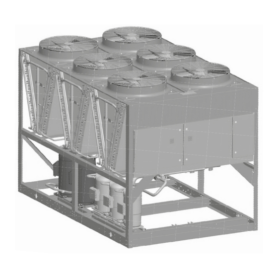
- Page 20 FORM 150.73-NM1 SECTION 2: PRODUCT DESCRIPTION ISSUE DATE: 07/03/2024 Unit components FAN ASSEMBLIES CONTROL PANEL COMPRESSORS CONDENSER COILS POWER PANEL FIGURE 2 - UNIT COMPONENTS FRONT JOHNSON CONTROLS...
- Page 21 FORM 150.73-NM1 SECTION 2: PRODUCT DESCRIPTION ISSUE DATE: 07/03/2024 DISCONNECT SWITCH FAN FUSES FAN CONTACTORS FAN CONTACTOR COMPRESSOR OVERLOADS XTBF1 COMPRESSOR CONTACTORS LD13247 FIGURE 3 - POWER PANEL COMPONENTS JOHNSON CONTROLS...
- Page 22 FORM 150.73-NM1 SECTION 2: PRODUCT DESCRIPTION ISSUE DATE: 07/03/2024 FAN FUSES MICROCOMPUTER CONTROL FAN CONTACTORS CONTROL RELAY CENTER MICROPANEL DISPLAY KEYPAD COMPRESSOR OVERLOADS XTBC1 MICROBOARD XTBC2 COMPRESSOR XTBF2 CONTACTORS LD13248 FIGURE 4 - POWER PANEL / CONTROL COMPONENTS JOHNSON CONTROLS...
- Page 23 Model (PIN 1-4) YLUA YLUA 0078 0078 0088 0088 0095 0095 0098 0098 0108 0108 0130 0130 0148 0148 0158 0158 Capacity (PIN 5-8) 0248 0248 0278 0278 0298 0298 0308 0308 0338 0338 0408 0408 0468 0468 0498 0498 JOHNSON CONTROLS...
- Page 24 N American Safety Code (cUL/cETL) Suction Temp Readout (standard)X SENSOR Suction Temp (PIN 25) Special Quote PUMP Motor Current Module (PIN 26) Motor Current Module (standard) REMOTE Remote Panel (PIN 27) Special Quote Sequence Kit (PIN 28) Special Quote JOHNSON CONTROLS...
- Page 25 PIN44 PIN 44 Special Quote Aluminum Coils Copper Fin Coils COILS Coils (PIN 45) Pre-Coated Fin Coils Post-Coated Dipped Coils Special Coils HEAT Heat Recovery (PIN 46) Special Quote FAN MOTORS Fan Motors (PIN 47) TEAO Fan Motors JOHNSON CONTROLS...
- Page 26 Sound Fans (PIN 52) Ultra Quiet Fans required Special Sound Fans required PAINT PIN 53 Special Quote No Isolators required 1" Deflection Isolators required ISOL Vibration Isolators (PIN 54) Neoprene Isolators required Seismic Isolators required Special Isolators required JOHNSON CONTROLS...
- Page 27 FORM 150.73-NM1 SECTION 2: PRODUCT DESCRIPTION ISSUE DATE: 07/03/2024 Refrigerant flow diagram LD04284A FIGURE 5 - REFRIGERANT FLOW DIAGRAM JOHNSON CONTROLS...
- Page 28 The fully condensed and subcooled liquid passes through the expansion valve where pressure is reduced and further cooling takes place before returning to the cooler. FIGURE 6 - PROCESS AND INSTRUMENTATION DIAGRAM JOHNSON CONTROLS...
- Page 29 Refer to Shipping Damage Claims Policy, Form 50.15-NM for more information and details. The form to submit for Chiller FOB destination inspection. Major damage must be reported immediately to your LD13357 local Johnson Controls representative. FIGURE 7 - UNIT RIGGING JOHNSON CONTROLS...
- Page 30 The unit must only be lifted by the base frame at the points provided. Never move the unit on rollers, or lift the unit using a forklift truck. Care should be taken to avoid damaging the condenser cooling fins when moving the unit. JOHNSON CONTROLS...
- Page 31 Location and clearances ment must be commissioned and serviced These units are designed for outdoor installations on by an authorized Johnson Controls ground level, rooftop, or beside a building. Due to the service mechanic or a qualified service properties of the refrigerant, never install the chiller in- person experienced in equipment instal- side a structure or without proper ventilation.
- Page 32 N.E.C. or local code requirements. Minimum circuit tions, each unit should be piped as shown. ampacity and maximum dual element fuse size are giv- en in Table 10 on page 45. JOHNSON CONTROLS...
- Page 33 See Figure 3 on page 21 and Figure 10 on page 41 and unit wiring diagrams for field and power wir- ing connections. See Section 8: Unit operation for a detailed description of operation concerning unit con- tacts and inputs. JOHNSON CONTROLS...
- Page 34 Control Mode. The System 1 zone thermostat is Evaporator blower start contacts field wired at XTBC1 terminals 13 to 51. On two sys- tem units, System 2 zone thermostat is field wired to For constant fan operation: Terminal block XTBC2 - JOHNSON CONTROLS...
- Page 35 Figure 10 on page 41, and Unit Wiring Diagram. mum operating efficiencies. System piping should conform to the Johnson Controls DX piping guide Alarm status contacts Form 050.40-ES2 or ASHRAE refrigeration handbook Normally-open contacts are available for each refriger- guidelines.
- Page 36 2 to 3 psi (13.8 to 20.7 kPa) FILTER/DRIER 2 to 3 psi (13.8 to 20.7 kPa) SIGHT GLASS 0.5 psi (3.4 kPa) * Pressure drops or equivalent length values are approximate. If more precise value is desired, consult ASHRAE Refrigerant Handbook. JOHNSON CONTROLS...
- Page 37 7/8 in. for the optional factory mounted hot gas bypass valve. Note: Hot gas bypass is only available for refrigerant system number 1. 7. For more information, refer to either the YORK DX Piping Guide (Form 050.40-ES2) or the ASHRAE Refrigeration Handbook. JOHNSON CONTROLS...
- Page 38 Liquid line filter driers, sight glass, and TXV’s are loads. The calculated information was based on main- field supplied for each refrigerant circuit. taining a minimum of 1000 fpm (5.08 m/s) refrigerant vapor velocity at full load. JOHNSON CONTROLS...
- Page 39 Hot gas bypass is only available for re- formance will result. In addition, pressure loss for frigerant system number 1. strainers, filter driers, solenoid valves, and isolation valve or fittings are not included in this table, and must be taken into account. JOHNSON CONTROLS...
- Page 40 MOUNTING BRACKET BLK (+5VDC) DRAIN (GND) REFER TO ASSEMBLY INSTRUCTIONS IN FACTORY SUPPLIED KIT FOR DISCHARGE AIR SENSOR AND ELECTRICAL CONNECTION HARDWARE SHIPPED WITH UNIT. J6 PIN IDENTIFICATION ON I/O LD13345 FIGURE 9 - DISCHARGE AIR SENSOR FIELD WIRING JOHNSON CONTROLS...
- Page 41 NO can result in damage to the evaporator LETHAL VOLTAGES are present inside and unit as a result of the chilled liquid the panel AFTER disconnecting power, freezing. before working on equipment. FIGURE 10 - CONTROL WIRING JOHNSON CONTROLS...
- Page 42 FORM 150.73-NM1 SECTION 4: INSTALLATION ISSUE DATE: 07/03/2024 THIS PAGE INTENTIONALLY LEFT BLANK. JOHNSON CONTROLS...
- Page 43 MAX. 200-3-60 Note 230-3-60 • For leaving brine temperature below 40°F (4.4°C), 380-3-60 contact your nearest Johnson Controls Office for 460-3-60 application requirements. 575-3-60 • For leaving water temperature higher than 55°F (12.8°C), contact the nearest Johnson Controls Office for application guidelines.
- Page 44 Number of rows Fins per in. Condenser Fans, Low Sound Number of fans, circuit 1/circuit 2 Fan HP Fan rpm 1,160 1,160 1,160 1,160 1,160 1,160 1,160 1,160 Total chiller CFM 62,400 62,400 62,400 93,600 93,600 93,600 12,800 12,800 JOHNSON CONTROLS...
- Page 45 AFTER disconnecting power, freezing. before working on equipment. TABLE 10 - VOLTAGE RANGE VOLTAGE RANGE VOLTAGE CODE UNIT POWER MINIMUM MAXIMUM 200-3-60 230-3-60 380/415-3-60 460-3-60 380/415-3-50 575-3-60 JOHNSON CONTROLS...
- Page 46 FUSE 0130 TABLE 12 - STANDARD EFFICIENCY UNIT ELECTRICAL DATA (5 COMPR) R-410A, SINGLE POINT SYSTEM # 1 DUAL COMPR 1 COMPR 2 Pump Volt Pump DUAL ELEM MODEL EFF. Model Code ELEM FUSE FUSE 0095 0148 0158 JOHNSON CONTROLS...
- Page 47 COMPR 3 COMPR 1 COMPR 2 COMPR 3 44.0 44.0 37.0 37.0 23.1 23.1 19.0 19.0 15.3 15.3 44.0 44.0 37.0 37.0 23.1 23.1 19.0 19.0 15.3 15.3 44.0 44.0 37.0 37.0 23.1 23.1 19.0 19.0 15.3 15.3 JOHNSON CONTROLS...
- Page 48 ELEM FUSE FUSE 0098 TABLE 15 - HIGH EFFICIENCY UNIT ELECTRICAL DATA (5 COMPR) R-410A, SINGLE POINT SYSTEM # 1 DUAL COMPR 1 COMPR 2 Pump Volt Pump DUAL ELEM MODEL Eff. Model Code ELEM FUSE FUSE 0108 JOHNSON CONTROLS...
- Page 49 TABLE 15 - HIGH EFFICIENCY UNIT ELECTRICAL DATA (5 COMPR) R-410A, SINGLE POINT, CONT’D SYSTEM # 1 SYSTEM # 2 COMPR 3 COMPR 1 COMPR 2 COMPR 3 44.0 44.0 37.0 37.0 23.1 23.1 19.0 19.0 15.3 15.3 JOHNSON CONTROLS...
- Page 50 COMPR 2 Pump Volt Pump DUAL ELEM MODEL Eff. Model Code N/F DS ELEM FUSE FUSE 48.5 48.5 48.5 48.5 0078 27.6 27.6 24.4 24.4 17.4 17.4 57.7 57.7 57.7 57.7 0088 30.9 30.9 26.9 26.9 21.5 21.5 JOHNSON CONTROLS...
- Page 51 24.4 19.0 17.4 15.3 17.4 17.4 17.4 15.3 57.7 44.0 48.5 48.5 48.5 44.0 57.7 37.0 48.5 48.5 48.5 37.0 30.9 23.1 27.6 27.6 27.6 23.1 26.9 19.0 24.4 24.4 24.4 19.0 21.5 15.3 17.4 17.4 17.4 15.3 JOHNSON CONTROLS...
- Page 52 TABLE 20 - HIGH EFFICIENCY UNIT ELECTRICAL DATA (6 COMPR) R-454B, SINGLE POINT SYSTEM # 1 DUAL COMPR 1 COMPR 2 Pump Volt Pump DUAL ELEM MODEL Eff. Model Code ELEM FUSE FUSE 57.7 57.7 57.7 57.7 0098 30.9 30.9 26.9 26.9 21.5 21.5 JOHNSON CONTROLS...
- Page 53 COMPR 3 COMPR 1 COMPR 2 COMPR 3 57.7 44.0 57.7 57.7 57.7 44.0 57.7 37.0 57.7 57.7 57.7 37.0 30.9 23.1 30.9 30.9 30.9 23.1 26.9 19.0 26.9 26.9 26.9 19.0 21.5 15.3 21.5 21.5 21.5 15.3 JOHNSON CONTROLS...
- Page 54 System 1 System 2 VOLT DUAL DUAL DUAL DUAL MODEL EFF MIN N/ MIN N/F Code ELEM ELEM ELEM ELEM FUSE and FUSE and FUSE and FUSE and MIN CB MAX CB MIN CB MAX CB 0095 0158 JOHNSON CONTROLS...
- Page 55 COMPR 3 COND FANS RLA LRA RLA LRA RLA LRA QTY LRA RLA LRA RLA LRA RLA LRA QTY 44.0 44.0 37.0 37.0 23.1 23.1 19.0 19.0 15.3 15.3 44.0 44.0 37.0 37.0 23.1 23.1 19.0 19.0 15.3 15.3 JOHNSON CONTROLS...
- Page 56 TABLE 25 - HIGH EFFICIENCY UNIT ELECTRICAL DATA (5 COMPR) R-410, DUAL POINT System 1 System 2 VOLT DUAL DUAL DUAL DUAL MODEL EFF MIN N/ MIN N/F Code ELEM ELEM ELEM ELEM FUSE and FUSE and FUSE and FUSE and MIN CB MAX CB MIN CB MAX CB 0108 JOHNSON CONTROLS...
- Page 57 COMPR 2 COMPR 3 COND FANS COMPR 1 COMPR 2 COMPR 3 COND FANS RLA LRA RLA LRA RLA LRA QTY LRA RLA LRA RLA LRA RLA LRA QTY 44.0 44.0 37.0 37.0 23.1 23.1 19.0 19.0 15.3 15.3 JOHNSON CONTROLS...
- Page 58 – – – – 0078 – – – – – – – – – – – – – – – – – – – – 0088 – – – – – – – – – – – – JOHNSON CONTROLS...
- Page 59 57.7 44.0 48.5 48.5 48.5 44.0 57.7 57.7 57.7 37.0 48.5 48.5 48.5 37.0 30.9 30.9 30.9 23.1 27.6 27.6 27.6 23.1 26.9 26.9 26.9 19.0 24.4 24.4 24.4 19.0 21.5 21.5 21.5 15.3 17.4 17.4 17.4 15.3 JOHNSON CONTROLS...
- Page 60 ELEM FUSE and FUSE and FUSE and FUSE and MIN CB MAX CB MIN CB MAX CB – – – – – – – – 0098 – – – – – – – – – – – – JOHNSON CONTROLS...
- Page 61 57.7 44.0 57.7 57.7 57.7 44.0 57.7 57.7 57.7 37.0 57.7 57.7 57.7 37.0 30.9 30.9 30.9 23.1 30.9 30.9 30.9 23.1 26.9 26.9 26.9 19.0 26.9 26.9 26.9 19.0 21.5 21.5 21.5 15.3 21.5 21.5 21.5 15.3 JOHNSON CONTROLS...
- Page 62 S6: (2) 250kcmil - 500kcmil (4) 4AWG - 500kcmil S5-400 S5: (2) 3/0 - 250kcmil S5-400 S5: (2) 3/0 - 250kcmil (4) 4AWG - 500kcmil S5-400 S5: (2) 3/0 - 250kcmil S5-400 S5: (2) 3/0 - 250kcmil (2) 4AWG - 500kcmil JOHNSON CONTROLS...
- Page 63 -58 = 575-3-60 FULL LOAD AMPS HERTZ MAXIMUM MINIMUM CIRCUIT AMPACITY MINIMUM MIN NF MINIMUM NON FUSED RATED LOAD AMPS S.P. WIRE SINGLE POINT WIRING UNIT MTD SERV SW UNIT MOUNTED SERVICE (NON-FUSED DISCONNECT SWITCH) LOCKED ROTOR AMPS JOHNSON CONTROLS...
- Page 64 Pump Contactor Part Wiring And Items Shown Thus Are Not - KP (Including Coil Suppressor) Supplied By York - KT Relay Timer Items Thus Enclosed Form A Compressor Motor Components Or Sets Of Components - MF Motor Fan 035-21966-101 REVG JOHNSON CONTROLS...
- Page 65 Input switch disconnect (standard on CE units) or circuit breaker option replaces input terminal block. Input switch disconnect and individual system circuit breaker option replaces input terminal block. 115V control circuit requires a 115V supply unless control circuit transformer -T2 and -F3 are fitted (standard on CE units). 035-21966-101 REVG JOHNSON CONTROLS...
- Page 66 Fitted on units with single phase motors only Fitted on units with low ambient option only Only fitted on units with an acoustic kit Only fitted on heat recovery units Only fitted on condensing units Omitted on condensing units 035-21966-101 REVG JOHNSON CONTROLS...
- Page 67 FORM 150.73-NM1 SECTION 5: TECHNICAL DATA ISSUE DATE: 07/03/2024 THIS PAGE INTENTIONALLY LEFT BLANK. JOHNSON CONTROLS...
- Page 68 FORM 150.73-NM1 SECTION 5: TECHNICAL DATA ISSUE DATE: 07/03/2024 Wiring Diagrams 035-21583-101 REV D FIGURE 11 - ELEMENTARY WIRING DIAGRAM JOHNSON CONTROLS...
- Page 69 FORM 150.73-NM1 SECTION 5: TECHNICAL DATA ISSUE DATE: 07/03/2024 FIGURE 11 - ELEMENTARY WIRING DIAGRAM (CONT’D) JOHNSON CONTROLS...
- Page 70 FORM 150.73-NM1 SECTION 5: TECHNICAL DATA ISSUE DATE: 07/03/2024 035-21583-102 REVD FIGURE 11 - ELEMENTARY WIRING DIAGRAM (CONT’D) JOHNSON CONTROLS...
- Page 71 FORM 150.73-NM1 SECTION 5: TECHNICAL DATA ISSUE DATE: 07/03/2024 FIGURE 11 - ELEMENTARY WIRING DIAGRAM (CONT’D) JOHNSON CONTROLS...
- Page 72 FORM 150.73-NM1 SECTION 5: TECHNICAL DATA ISSUE DATE: 07/03/2024 FIGURE 11 - ELEMENTARY WIRING DIAGRAM (CONT’D) JOHNSON CONTROLS...
- Page 73 FORM 150.73-NM1 SECTION 5: TECHNICAL DATA ISSUE DATE: 07/03/2024 FIGURE 11 - ELEMENTARY WIRING DIAGRAM (CONT’D) JOHNSON CONTROLS...
- Page 74 FORM 150.73-NM1 SECTION 5: TECHNICAL DATA ISSUE DATE: 07/03/2024 035-21589-107 REV A FIGURE 11 - ELEMENTARY WIRING DIAGRAM (CONT’D) JOHNSON CONTROLS...
- Page 75 FORM 150.73-NM1 SECTION 5: TECHNICAL DATA ISSUE DATE: 07/03/2024 FIGURE 11 - ELEMENTARY WIRING DIAGRAM (CONT’D) JOHNSON CONTROLS...
- Page 76 FORM 150.73-NM1 SECTION 5: TECHNICAL DATA ISSUE DATE: 07/03/2024 035-21589-106 REVE FIGURE 11 - ELEMENTARY WIRING DIAGRAM (CONT’D) JOHNSON CONTROLS...
- Page 77 FORM 150.73-NM1 SECTION 5: TECHNICAL DATA ISSUE DATE: 07/03/2024 FIGURE 11 - ELEMENTARY WIRING DIAGRAM (CONT’D) JOHNSON CONTROLS...
- Page 78 FORM 150.73-NM1 SECTION 5: TECHNICAL DATA ISSUE DATE: 07/03/2024 Power options connection diagram 035-21589-103 REVB LD13234A FIGURE 12 - POWER OPTIONS CONNECTION DIAGRAM JOHNSON CONTROLS...
- Page 79 FORM 150.73-NM1 SECTION 5: TECHNICAL DATA ISSUE DATE: 07/03/2024 LD13901 FIGURE 12 - POWER OPTIONS CONNECTION DIAGRAM (CONT’D) JOHNSON CONTROLS...
- Page 80 FORM 150.73-NM1 SECTION 5: TECHNICAL DATA ISSUE DATE: 07/03/2024 035-21589-101 REVC FIGURE 12 - POWER OPTIONS CONNECTION DIAGRAM (CONT’D) JOHNSON CONTROLS...
- Page 81 FORM 150.73-NM1 SECTION 5: TECHNICAL DATA ISSUE DATE: 07/03/2024 FIGURE 12 - POWER OPTIONS CONNECTION DIAGRAM (CONT’D) JOHNSON CONTROLS...
- Page 82 FORM 150.73-NM1 SECTION 5: TECHNICAL DATA ISSUE DATE: 07/03/2024 035-21583-116_rev - FIGURE 13 - SINGLE POINT AND DUAL POINT WIRING JOHNSON CONTROLS...
- Page 83 FORM 150.73-NM1 SECTION 5: TECHNICAL DATA ISSUE DATE: 07/03/2024 THIS PAGE INTENTIONALLY LEFT BLANK. JOHNSON CONTROLS...
- Page 84 FORM 150.73-NM1 SECTION 5: TECHNICAL DATA ISSUE DATE: 07/03/2024 Wiring 035-21583-106 REVA LD13238 FIGURE 14 - WIRING JOHNSON CONTROLS...
- Page 85 FORM 150.73-NM1 SECTION 5: TECHNICAL DATA ISSUE DATE: 07/03/2024 LD13239 FIGURE 14 - WIRING (CONT’D) JOHNSON CONTROLS...
- Page 86 FORM 150.73-NM1 SECTION 5: TECHNICAL DATA ISSUE DATE: 07/03/2024 Micro panel connections 035-21589-102 REVD FIGURE 15 - MICRO PANEL CONNECTIONS JOHNSON CONTROLS...
- Page 87 FORM 150.73-NM1 SECTION 5: TECHNICAL DATA ISSUE DATE: 07/03/2024 FIGURE 15 - MICRO PANEL CONNECTIONS (CONT’D) JOHNSON CONTROLS...
- Page 88 FORM 150.73-NM1 SECTION 5: TECHNICAL DATA ISSUE DATE: 07/03/2024 035-21583-103 REV. B LD13992A FIGURE 16 - ELEMENTARY DIAGRAM JOHNSON CONTROLS...
- Page 89 FORM 150.73-NM1 SECTION 5: TECHNICAL DATA ISSUE DATE: 07/03/2024 LD13993A FIGURE 16 - ELEMENTARY DIAGRAM (CONT’D) JOHNSON CONTROLS...
- Page 90 FORM 150.73-NM1 SECTION 5: TECHNICAL DATA ISSUE DATE: 07/03/2024 035-21589-105 REVA FIGURE 16 - ELEMENTARY DIAGRAM (CONT’D) JOHNSON CONTROLS...
- Page 91 FORM 150.73-NM1 SECTION 5: TECHNICAL DATA ISSUE DATE: 07/03/2024 FIGURE 16 - ELEMENTARY DIAGRAM (CONT’D) JOHNSON CONTROLS...
- Page 92 Site restrictions may compromise minimum clearances indicated below, resulting in unpredictable airflow patterns and possible diminished performance. Johnson Controls unit controls will optimize operation without nuisance high-pressure safety cutouts; however, the system designer must consider potential performance degradation. Access to the unit control center assumes the unit is no higher than on spring isolators.
- Page 93 Site restrictions may compromise minimum clearances indicated below, resulting in unpredictable airflow patterns and possible diminished performance. Johnson Controls unit controls will optimize operation without nuisance high-pressure safety cutouts; however, the system designer must consider potential performance degradation. Access to the unit control center assumes the unit is no higher than on spring isolators.
- Page 94 Site restrictions may compromise minimum clearances indicated below, resulting in unpredictable airflow patterns and possible diminished performance. Johnson Controls unit controls will optimize operation without nuisance high-pressure safety cutouts; however, the system designer must consider potential performance degradation. Access to the unit control center assumes the unit is no higher than on spring isolators.
- Page 95 LD13243 NOTES: 1. No obstructions allowed above the unit. 2. Only one adjacent wall may be higher than the unit. 3. Adjacent units should be 10 ft (3 m) apart. FIGURE 17 - UNIT CLEARANCES – ALL MODELS JOHNSON CONTROLS...
- Page 96 Order No: 082533060301 tion will be available when the specific chiller/ option Line No: selection is made from the local Johnson Controls sales office. Be aware, weights will change with each op- Product: YLUA tion along with possible isolator changes. Weights and...
- Page 97 1149 thru 1530 522 - 694 C2P-1D-2400 GRAY 1531 thru 2040 695 - 925 C2P-1D-2400 GRAY 1531 thru 2040 695 - 925 C2P-1D-2720 WHITE 2041 thru 2312 926 - 1049 C2P-1D-3570N GRAY/RED 2313 thru 3570 1050 - 1619 JOHNSON CONTROLS...
- Page 98 (See drawing below). in. maximum difference can be tolerated). 9. Fine adjust isolators to level equipment. 4. Bolt or anchor all isolators to supporting structure 10. Installation is complete. utilizing base slotted holes (“c”). LD13790 JOHNSON CONTROLS...
- Page 99 741 to 1020 337 to 463 Y2RSI-2D-1690 PINK 1021 to 1437 464 to 652 Y2RSI-2D-2640N PINK/GRAY 1438 to 2244 653 to 1018 Y2RSI-2D-2870N PINK/GRAY/ORANGE 2245 to 2618 1019 to 1188 Y2RSI-2D-3280N PINK/GRAY/DK.BROWN 2619 to 3740 1189 to 1696 JOHNSON CONTROLS...
- Page 100 (2) 5/8 unc a325 grade 5 sae bolt or weld equip- ment or bracket to the top plate ("a") of isolator ("G") ("E") ("A") ("A") ("E") GROMMET 1/4 - 3/8 GAP EQUIPMENT ("F") WASHER ("E") ("F") ("C") ("C") ("B") LD13763A JOHNSON CONTROLS...
- Page 101 VMC PART NUMBER VMC ISOL. COLOR WEIGHT RANGE (LBS) WEIGHT RANGE (KGS) RD-3-CHARCOAL-WR CHARCOAL Up thru 825 UP TO 374 RD-4-BRICK RED-WR BRICK RED 826 thru 1688 375 - 766 RD-4-CHARCOAL-WR CHARCOAL 1689 thru 4000 767 - 1814 JOHNSON CONTROLS...
- Page 102 Recommends that the isolator base ("a") be in- stalled on a level surface. Shim or grout as re- quired, leveling all isolator bases to the same Elevation (1/32-in. maximum difference can be tolerated). TOP BOLT ("B") TOP WASHER ("C") ("B") ("A") SECTION D-D LD13762B JOHNSON CONTROLS...
- Page 103 Service and oil line valves Commissioning of this unit should only Open each compressor suction and discharge service be carried out by Johnson Controls Au- valve. If valves are of the back-seat type, open them thorized personnel. fully (counterclockwise) then close one turn of the stem to ensure operating pressure is fed to pressure transducers.
- Page 104 The machine is now live! tomer’s ductwork and wired into the control panel cor- rectly using shielded cable. The air flow switch should be connected to terminals 13, 50 and 51 of XTBC1 on the panel. (See Figure 10 on page 41). JOHNSON CONTROLS...
- Page 105 Form: 150.73-CL2 (1023) Customer: ______________________________________ Job name: ______________________________________ Address: _______________________________________ Location: _______________________________________ Phone: _________________________________________ Customer order number: __________________________ Johnson Controls phone number: Johnson Controls order number: Johnson Controls contract number: ___________________________ ___________________________ _______________________________ Chiller model number: ____________________________ Unit serial number: ______________________________...
- Page 106 Fan control on pressure Fan differential off pressure Total number of compressors * Number of fans/system * Unit/system voltage Unit ID * System 1 superheat setpoint * System 2 superheat setpoint * Not on all models ** Viewable Only Johnson Controls JOHNSON CONTROLS...
- Page 107 (approximately 15 minutes) between adjustments for the system and the thermal expan- sion valve to respond and stabilize. Ensure that superheat is set at a minimum of 10°F (5.56°C) with a single compressor running on each circuit. Johnson Controls JOHNSON CONTROLS...
- Page 108 5000 Renaissance Drive, New Freedom, Pennsylvania USA 17349 1-800-524-1330 Subject to change without notice. Printed in USA Copyright © by Johnson Controls 2023 www.johnsoncontrols.com All Rights Reserved Form 150.73-CL2 (1023) Issue Date: October **, 2023 Supersedes: 150.73-CL2 (1012)
- Page 109 Transformer, which supplies 12 VAC to the bridge diode activate the unit. module. The Bridge Diode Module rectifies the voltage to -12 V unreg. The +12 V unreg voltage supplies power to the Remote Temp. Reset Circuit Board. JOHNSON CONTROLS...
- Page 110 It is essential the user become familiar with the use of the keypad and display. This will allow the user to make full use of the capabilities and diagnostic features available. JOHNSON CONTROLS...
- Page 111 The DAILY SCHEDULE SHUTDOWN message in- for system 1 and system 2 are open. These messages dicates that the daily/holiday schedule programmed is will only be displayed when the control mode is pro- keeping the unit from running. grammed for Suction Pressure JOHNSON CONTROLS...
- Page 112 180 seconds, whichever S Y S S U C T L I M I T I N G comes first, the compressor will cycle off. S Y S S U C T L I M I T I N G JOHNSON CONTROLS...
- Page 113 This sensor protects the scrolls on this safety or any safety, immediate from overheating due to inadequate cooling that may steps should be taken to identify the cause. occur when refrigerant charge is low, or superheat is too high. JOHNSON CONTROLS...
- Page 114 Restart can occur when temperature rises 2°F S Y S L O W D S C H S H E A T above the cutoff. S Y S L O W D S C H S H E A T JOHNSON CONTROLS...
- Page 115 PRO- GRAM key is pressed. Once PROGRAM is pressed the anti-recycle timers will be set to the programmed anti-recycle time to allow the operator time to check setpoints, and if necessary, reprogram programmable values and options. JOHNSON CONTROLS...
- Page 116 System X Pumping Down (on shutdown) LD13346 * Only displayed when unit control mode programmed for Discharge Air Temperature. ** Only displayed when unit control mode programmed for Suction Pressure. FIGURE 19 - STATUS KEY MESSAGES QUICK REFERENCE LIST JOHNSON CONTROLS...
- Page 117 0.4°F (-17.6°C). The With the “UNIT TYPE” set as a condensing unit (via maximum limit on the display is 131.2°F (55.1°C). jumper between J11-7 and J11-12 on the I/O Board), the following list of operating data screens are view- JOHNSON CONTROLS...
- Page 118 30 seconds or if the contacts have been closed compressors on the unit. in the last 30 seconds. A total of 99,999 hours and starts can be logged before the counter rolls over to “0”. JOHNSON CONTROLS...
- Page 119 Oper data quick reference list S Y S L L S V H O T G A S S O L O F F S Y S F A N S T A G E JOHNSON CONTROLS...
- Page 120 ** Only displayed when Control Mode is programmed for Discharge EVAPORATOR HEATER Air Temperature Control. ACTIVE REMOTE CONTROL NONE UNIT XXX.X AMPS X.X VOLTS FIGURE 20 - OPERATION DATA SOFTWARE VERSION C.M08.14.02 Print key The PRINT key allows the operator to obtain a printout JOHNSON CONTROLS...
- Page 121 See Service And Troubleshooting section for Printer Installation information. YORK INTERNATIONAL CORPORATION MILLENNIUM CONDENSING UNIT SAFETY SHUTDOWN NUMBER 1 SHUTDOWN @ 3:56PM 29 JAN 08 SYS 1 HIGH DSCH PRESS SHUTDOWN SYS 2 NO FAULTS JOHNSON CONTROLS...
- Page 122 Displays the programmed Discharge Pressure Cutout. A M B I E N T C O N T R O L X X X X X X X X X X Displays the type of Ambient Control; Standard or Low Ambient. JOHNSON CONTROLS...
- Page 123 X X - X X - X X - X X D - H - M - S Displays the programmed Setpoint and Range, if the unit is programmed for Discharge Air Control. Displays the system run time when the fault occurred. JOHNSON CONTROLS...
- Page 124 RENT FEEDBACK ONE PER UNIT under the pro- gram key, the display will be the first display prior to the SYS 1 info. If the micro is programmed for CUR- RENT FEEDBACK NONE, no current display will appear. JOHNSON CONTROLS...
- Page 125 The ↑ (UP) arrow key and ↓ (DOWN) arrow key are also used for programming the control panel such as changing numerical or text values when programming cooling setpoints, setting the daily schedule, changing safety setpoints, unit options, and setting the clock. JOHNSON CONTROLS...
- Page 126 C O N T R O L the jumper between J11-7 and J11-12 on the I/O Board. This message indicates that the cooling setpoint is un- der REMOTE control. When under remote control, the cooling setpoint will be determined by a remote device JOHNSON CONTROLS...
- Page 127 13 - 20). See the section on Operating Controls for a The setpoint and range are programmed with the UP detailed explanation of this feature. arrow. DOWN arrow, and ENTER/ADV key as de- scribed in the previous setpoint message. The setpoints JOHNSON CONTROLS...
- Page 128 DISCHARGE PRESSURE CUTOUT is the discharge DOWN arrow, and ENTER/ADV keys. pressure at which the system will shutdown as moni- tored by the optional discharge transducer. This is a software shutdown that acts as a backup for the me- JOHNSON CONTROLS...
- Page 129 The timer begins to count down. If all the compressors on the unit model. in the circuit cycle off, a compressor within the circuit This MUST be programmed correctly to will not be permitted to start until the anti-recycle timer ensure proper condensing unit operation. JOHNSON CONTROLS...
- Page 130 P R O G R A M M E D When communications is required with a BAS or Op- tiView Panel, individual unit IDs are necessary for communications with specific units on a single RS-485 line. ID 0-7 is selectable. JOHNSON CONTROLS...
- Page 131 Per Unit Remote Unit Id * The minimum discharge pressure allowed is 160 psig. The fan differential Off Pressure will be lowered to prevent going below 235 psig based on where the fan control On Pressure is programmed. JOHNSON CONTROLS...
- Page 132 Fan Differential Off-Pressure Total Numbers Compressors Number of Fans Per System YCUL0096 - 0130 ONLY SYS / Unit Trip Volts Option Remote Unit ID SYS 1 and 2 Superheat Setpoints LD08696 FIGURE 21 - SETPOINTS QUICK REFERENCE LIST JOHNSON CONTROLS...
- Page 133 If the kit is NOT installed, S Y S S W I T C H O F F and low ambient is selected, low pressure faults and This turns system 2 off compressor damage may occur. JOHNSON CONTROLS...
- Page 134 P R E S S Condenser fans are controlled by ambient temperature This mode displays system operating values in Impe- and discharge pressure. This mode must be chosen if rial units of °F or psig. the discharge pressure transducers are not installed. JOHNSON CONTROLS...
- Page 135 This mode should be selected when an optional mod- ule is installed to allow individual current monitoring of each system. SYS 1 input is to J7-4 to J7-12 of the micro. SYS 2 input is to J9-4 to J9-12 of the micro. JOHNSON CONTROLS...
- Page 136 FLASH CARD UPDATE TO “ENABLED” using the ↑ and ↓ keys. F L A S H C A R D U P D A T E E N A B L E D JOHNSON CONTROLS...
- Page 137 Also see the UNIT KEYS PROGRAMMING QUICK hour, minute, meridian; day, month, and year are dis- REFRENCE LIST in Figure 22 on page 138. played. Pressing the ENTER/ADV Key will save the valve and move the cursor on to the next programma- ble variable. JOHNSON CONTROLS...
- Page 138 "Condensing Unit" MUST be Selected Via Jumper Installed (Viewable Only) Refrigerant Type R410A (Programmed Under Service Mode) (Viewable Only LD13348 Figure 22 provides a quick reference list for the Unit key setpoints. FIGURE 22 - UNIT KEYS PROGRAMMING QUICK REFERENCE LIST JOHNSON CONTROLS...
- Page 139 Low Limit, unloading occurs at a rate of 60 sec- onds. The sequences of Capacity Control (compressor stag- ing) for loading and unloading are shown in Table 34 on page 140 and Table 35 on page 140. JOHNSON CONTROLS...
- Page 140 * STEP can be viewed using the OPER DATA key and scrolling to COOLING DEMAND. 4. Each system will attempt to rotate the lead compressor start sequence to help even out the run hours in a system, therefore piping suction risers should be sized off the smallest compressor capacity in either system. JOHNSON CONTROLS...
- Page 141 (no compressor staging) loading 117 psig (8.0 bar) 126 psig (8.7 bar) Setpoint 121 psig (8.3 bar) Setpoint = 121 psig (8.3 bar) Control Range = 5 psig ( 0.35 bar) FIGURE 24 - SUCTION PRESSURE CONTROL JOHNSON CONTROLS...
- Page 142 If the lead system has run for less than 5 minutes, 3 times in a row, the anti-recycle timer will be extended to 10 minutes. JOHNSON CONTROLS...
- Page 143 * NOTE: STEP 2 is not active in the “Standard Ambient” mode. When changing to “Low Ambient” control, fan power wiring also changes. Fan #4 Fan #3 Fan #1 LD07403A Fan #2 FIGURE 25 - YLUA0078 – YLUA0095 FAN LOCATION (TYPICAL) JOHNSON CONTROLS...
- Page 144 2 and [Diff Press. + 40 psig 2 FANS 3 FWD 4 FWD + 40 psig (2.76 Bars)] TB7-10 TB10-10 (2.76 Bars) When Low Ambient Control of the fans is selected, fan control will be by discharge pressure only. JOHNSON CONTROLS...
- Page 145 [(Diff Press.) + 40 psig + 40 psig (2.76 and 7 and 8 (2.76 Bars)] TB10-10 Bars) TB7-10 FAN #5 FAN #3 FAN #6 FAN #1 FAN #2 FAN #4 LD14098 FIGURE 26 - YLUA0098 – YLUA0130 FAN LOCATION JOHNSON CONTROLS...
- Page 146 13M, and 5 and 9 5, 7 6, 8 (4.14 Bars) (4.14 Bars)] FAN #7 FAN #5 FAN #3 FAN #1 FAN #8 FAN #2 FAN #6 LD14099 FAN #4 FIGURE 27 - YLUA0148 – YLUA0158 FAN LOCATION JOHNSON CONTROLS...
- Page 147 3, 5 and 6 compressor units. Table 41 on page 147 conditions allow the unit to operate. shows the load limiting permitted for the various num- bers of compressors. TABLE 41 - COMPRESSOR OPERATION – LOAD LIMITING COMPRESSORS STAGE 1 STAGE 2 IN UNIT JOHNSON CONTROLS...
- Page 148 * Max Reset Value is the “Max EMS-PWM Remote Temp. Reset” setpoint value described in the programming section under Cool- ing Setpoints. Programmable values are from 2 °F to 40 °F (1.11 °C to 11.11 °C). ** Note: The Suction Pressure Setpoints are not remotely resettable. JOHNSON CONTROLS...
- Page 149 LLSV is energized. Energizing and de-energizing outputs may be useful during trouble- Following is the order of outputs that will appear as the ENTER/ADV key is pressed: shooting. JOHNSON CONTROLS...
- Page 150 This example indicates that the system 1 suction pres- sure input is connected to plug 7 – pin 10 (J7-10) on the I/O board. It indicates that the voltage is 2.1 volts dc which corresponds to 81 psig (5.6 bars) suction pres- sure. JOHNSON CONTROLS...
- Page 151 Leaving Chilled Liquid Temp. Sensor (Not Used) J6-8 Discharge Air Temp Sensor J9-10 SYS 2 Suction Pressure Transducer J9-11 SYS 2 Discharge Pressure Transducer J7-12 Unit/SYS 1 Voltage J9-12 SYS 2 Voltage TABLE 45 - I/O ANALOG OUTPUTS Not Applicable JOHNSON CONTROLS...
- Page 152 FORM 150.73-NM1 SECTION 9: SERVICE AND TROUBLESHOOTING ISSUE DATE: 07/03/2024 I/O BOARD BOARD TB10 LD12721 FIGURE 28 - MICROBOARD LAYOUT JOHNSON CONTROLS...
- Page 153 J6-6 = +5 VDC regulated supply to sensor. J6-9 = VDC input signal to the microboard. See Table 46 on page 153 for voltage readings that correspond to specific outdoor tempera- tures. J6-3 = drain (shield connection = 0 VDC) Return JOHNSON CONTROLS...
- Page 154 All voltage reading are in ref- 3.56 5370 erence to ground (unit case). 3.61 5096 3.67 4837 3.72 4593 3.76 4363 3.81 4145 3.86 3941 3.90 3747 3.94 3564 3.98 3392 4.02 3228 4.06 3074 4.10 2928 4.13 2790 JOHNSON CONTROLS...
- Page 155 J7-11 = drain (shield connection = 0 VDC) J7-11 = VDC input signal to the microboard. See the formula above for voltage readings that correspond to specific discharge pressures. J7-7 = +5 VDC return J7-2 = drain (shield connection = 0 VDC) JOHNSON CONTROLS...
- Page 156 COMPR 3 (6) SYS 2 TB10-7 HGSV TB10-8 TB10 SYS 2 TB10-9 FAN 2 SYS 2 TB10-10 FAN 4 TB8-6 EVAP PUMP TB8-7 HEAT EXCH TB8-2 HEATER * Not Used LD12722 FIGURE 29 - I/O BOARD RELAY CONTACT ARCHITECTURE JOHNSON CONTROLS...
- Page 157 4. One 25 pin Cannon connector and shell. Display section. Connector: Cannon P/N DB-25P or equivalent. Johnson Controls recommends the field tested WEIGH- Shell: Cannon P/N DB-C2-J9. TRONIX model 1220 printer (or former IMP 24). This is a compact low cost printer that is ideal for service Assembly and wiring work and data logging.
- Page 158 5. Reduced air flow. 5. Check air flow. 6. Defective Suction Pressure 6. Replace Transducer/Low Pressure Transducer/Low Pressure Switch or Switch or faulty wiring. See Section wiring. 9: Service and troubleshooting for pressure/voltage formula. 7. LLSV defective. 7. Replace LLSV. JOHNSON CONTROLS...
- Page 159 4. Compressor failure. 4. Diagnose cause of failure and replace. 1. Check DX Coil. 1. Contact the local Johnson Controls service representative. 2. Improper air flow through the DX 2. Reduce flow to within unit design LACK OF COOLING EFFECT Coil.
- Page 160 FORM 150.73-NM1 ISSUE DATE: 07/03/2024 THIS PAGE INTENTIONALLY LEFT BLANK. JOHNSON CONTROLS...
- Page 161 Exercise care when cleaning the MCHX does not cover other related system components which so that the fins are not damaged. may or may not be provided by Johnson Controls. Sys- tem components must be maintained according to the individual manufacture’s recommendations as their operation affects the operation of the chiller.
- Page 162 3. Apply a coil cleaning solution approved by John- 1. Remove surface debris such as dirt, leaves, in- son Controls. Johnson Controls approves the use sects or fibers with a vacuum cleaner having a of RectorSeal brand GulfCleanTM coil cleaner, or soft brush attachment.
- Page 163 Controls in the condenser coil repair guide. 3. Apply a coil cleaning solution approved by John- Steps to touch-up small sections of son Controls. Johnson Controls approves the use finned coil surface of RectorSeal brand GulfClean coil cleaner on Environment Guard Premium microchannel coils 1.
- Page 164 ‘major’ service once a year. the chiller is equipped with the -20°F op- It is recommended that your local Johnson Controls tion, applying power to an empty chilled Service Center is contacted for recommendations for liquid system will cause the evaporator individual sites.
- Page 165 In addition to the checks listed on this page, perform periodic overall inspections on the unit to ensure prop- er equipment operation. Investigate and correct imme- diately items such as loose hardware, component op- eration, refrigerant leaks, and unusual noises. JOHNSON CONTROLS...
- Page 166 SYS 2 lated to the communications protocol type 92-95 Analog Suction Superheat utilized. The latest point map information (EEV Only) is listed on the Johnson Controls Group SYS 2 96-99 Analog Equipment Integration website. Anti-Recycle Timer SYS 2 EEV Output %...
- Page 167 Fault Code Digital ---- Coded ---- * The operational and fault codes sent to BAS pages 56 through 59 are defined in Table 42. Note that this table of fault and operational codes is for all DX products. JOHNSON CONTROLS...
- Page 168 COMPRESSOR(S) RUNNING GROUND FAULT HEAT PUMP LOAD LIMITING MP /HPCO LOW EVAPORATOR TEMPERATURE INCORRECT REFRIGERANT PROGRAMMED POWER FAILURE, MANUAL RESET REQUIRED UNIT MOTOR CURRENT LOW SUPERHEAT SENSOR FAIL DISCHARGE INHIBIT MP/HPCO INHIBIT PUMP TRIP PUMP FAIL MAKE FLOW JOHNSON CONTROLS...
- Page 169 P2 BAUD RATE P1 PROTOCOL XXXXX XXXXXX P1 MANUAL MAC P2 PARITY XXXXX ADDRESS P2 STOP BITS P1 BAUD RATE XXXXX REAL TIME ERROR P1 PARITY XXXXX RESET 1 = YES, 0 = NO 0 P1 STOP BITS JOHNSON CONTROLS...
- Page 170 English Text Too Long Floating Point Exception Get Packet Failed Get Type Failed Invalid Unit Conversion Invalid Hardware Selection Real Time Fault Spanish Text Too Long Thread Exited Thread Failed Thread Stalled Io Board Reset Bram Invalid Bacnet Setup Failed JOHNSON CONTROLS...
- Page 171 SYS 1 Suction Temperature (EEV And Cond Unit Only) Ambient Air Temperature S1_SUCT_SH SYS 1 Suction Superheat (EEV Only) S1_RUN_TIME SYS 1 Run Time (Seconds) S1_SUCT_PR SYS 1 Suction Pressure S1_DSCH_PR SYS 1 Discharge Pressure S1_CIR_TEMP SYS 1 Cooler Inlet Refrigerant Temperature (R-407C Only) JOHNSON CONTROLS...
- Page 172 Cooling Range 2 (SP Control) HEAT_RANGE Heating Range (HP Only) S1_DSCH_TEMP SYS 1 Discharge Temperature (EEV Only) S1_DSCH_SH SYS 1 Discharge Superheat (EEV Only) S2_DSCH_TEMP SYS 2 Discharge Temperature (EEV Only) S2_DSCH_SH SYS 2 Discharge Superheat (EEV Only) JOHNSON CONTROLS...
- Page 173 Ambient Control Mode (O = STD AMB, 1 = LOW AMB) CNTL_MODE_ Local / Remote Control Mode (0 = Local, 1 = Remote) DATA_UNIT Units (0 = Imperial, 1 = SI) AUTO_LL Lead / Lag Control Mode (0 = Manual, 1 = Auto) JOHNSON CONTROLS...
- Page 174 73.3 147.2 75.6 150.8 77.8 154.4 80.0 82.2 161.6 84.4 165.2 86.7 168.8 88.9 172.4 91.1 93.3 179.6 95.6 183.2 97.8 186.8 100.0 190.4 102.2 104.4 197.6 106.7 201.2 108.9 204.8 111.1 208.4 113.3 115.6 215.6 117.8 219.2 JOHNSON CONTROLS...
- Page 175 16.55 12.5 181.3 17.24 188.5 17.93 13.5 195.8 18.62 19.31 14.5 210.3 217.5 20.69 15.5 224.8 21.38 22.07 16.5 239.3 22.76 246.5 23.45 17.5 253.8 24.14 24.83 18.5 268.3 25.52 275.5 26.21 19.5 282.8 26.9 27.59 20.5 297.3 JOHNSON CONTROLS...
- Page 176 FORM 150.73-NM1 SECTION 10: MAINTENANCE ISSUE DATE: 07/03/2024 TABLE 63 - R-454B PRESSURE-TEMPERATURE CHART psig Temp. ˚F psig Temp. ˚F – – – – – JOHNSON CONTROLS...
- Page 177 FORM 150.73-NM1 SECTION 10: MAINTENANCE ISSUE DATE: 07/03/2024 THIS PAGE INTENTIONALLY LEFT BLANK. JOHNSON CONTROLS...
- Page 178 5000 Renaissance Drive, New Freedom, Pennsylvania USA 17349 1-800-524-1330 Subject to change without notice. Printed in USA Copyright © by Johnson Controls 2024 www.johnsoncontrols.com All Rights Reserved Form 150.73-NM1 (724) Issue Date: July 03, 2024 Supersedes: 150.73-NM1 (1223)
Need help?
Do you have a question about the YORK YLUA0078Z Series and is the answer not in the manual?
Questions and answers