Sign In
Upload
Manuals
Brands
Johnson Controls Manuals
Heat Pump
YORK YLUA0158
Johnson Controls YORK YLUA0158 Manuals
Manuals and User Guides for Johnson Controls YORK YLUA0158. We have
1
Johnson Controls YORK YLUA0158 manual available for free PDF download: Installation Operation & Maintenance
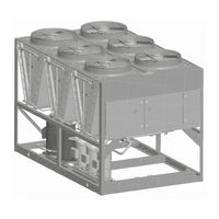
Johnson Controls YORK YLUA0158 Installation Operation & Maintenance (178 pages)
Air-Cooled Scroll Condensing Units, Style A and B 60 Hz, 80 ton to 160 ton, 281 kW to 522 kW
Brand:
Johnson Controls
| Category:
Heat Pump
| Size: 9 MB
Table of Contents
General Safety Guidelines
2
Safety Symbols
2
Revision Notes
3
Table of Contents
5
Section 1: General Equipment Information and Safety
11
Introduction
11
Compressors
11
Condenser
11
Refrigerant Circuit
11
Warranty
11
Safety and Quality
12
Responsibility for Safety
12
About this Manual
12
Misuse of Equipment
13
Structural Support
13
Emergency Shutdown
14
Safety Labels
14
Section 2: Product Description
15
Introduction
15
General System Description
15
FIGURE 1 - Compressors
15
Refrigerant Circuit
16
Microcomputer Control Center
16
High Ambient Kit
17
Communications
17
Power Panel
17
Accessories and Options
17
Power Options
17
Control Options
18
Unit Components
20
FIGURE 2 - Unit Components Front
20
FIGURE 3 - Power Panel Components
21
FIGURE 4 - Power Panel / Control Components
22
Nomenclature (Pin)
23
TABLE 1 - Product Identification Number (Pin)
23
Refrigerant Flow Diagram
27
FIGURE 5 - Refrigerant Flow Diagram
27
Process and Instrumentation Diagram
28
FIGURE 6 - Process and Instrumentation Diagram
28
Section 3: Handling and Storage
29
Delivery and Storage
29
Inspection
29
Unit Rigging
29
FIGURE 7 - Unit Rigging
29
Installation Checklist
31
Handling
31
Section 4: Installation
31
Location and Clearances
31
Rooftop Locations
31
Spring Isolators: Optional
32
Compressor Mounting
32
Pipework Arrangement
32
Ductwork Connection
32
Wiring
32
Compressor Heaters
33
Relief Valves
33
High Pressure Cutout
33
Electrical Wiring
33
Compressor Heaters
35
Refrigerant Piping
35
TABLE 2 - Fitting Equivalent Lengths
36
TABLE 3 - Refrigerant Piping Charges
36
TABLE 4 - Miscellaneous Liquid Line Pressure Drops
36
TABLE 5 - Refrigerant Line Connections
37
Oil Traps
38
Refrigerant Charge
38
Filter Driers, Sight Glasses, and TXV'S
38
Refrigerant Piping Notes
39
TABLE 6 - Refrigerant Line Pressure Drops (English)
39
Power Panel
40
Control Panel
40
FIGURE 8 - Single-Point Supply Connection - Terminal Block, Non-Fused Disconnect Switch
40
FIGURE 9 - Discharge Air Sensor Field Wiring
40
Control Wiring
41
FIGURE 10 - Control Wiring
41
Section 5: Technical Data
43
Operational Limitations
43
TABLE 7 - Voltage Limitations
43
Physical Data
44
TABLE 8 - Physical Data (English)
44
Electrical Data
45
TABLE 9 - Micro Panel Power Supply
45
TABLE 10 - Voltage Range
45
TABLE 11 - Standard Efficiency Unit Electrical Data (4 Compr) R-410A, Single Point
46
TABLE 12 - Standard Efficiency Unit Electrical Data (5 Compr) R-410A, Single Point
46
TABLE 13 - Standard Efficiency Unit Electrical Data (6 Compr) R-410A, Single Point
48
TABLE 14 - High Efficiency Unit Electrical Data (5 Compr) R-410A, Single Point
49
TABLE 15 - High Efficiency Unit Electrical Data (6 Compr) R-410A, Single Point
49
TABLE 16 - Standard Efficiency Unit Electrical Data (4 Compr) R-454B, Single Point
50
TABLE 17 - Standard Efficiency Unit Electrical Data (5 Compr) R-454B, Single Point
50
TABLE 18 - Standard Efficiency Unit Electrical Data (6 Compr) R-454B, Single Point
50
TABLE 19 - High Efficiency Unit Electrical Data (5 Compr) R-454B, Single Point
52
TABLE 20 - High Efficiency Unit Electrical Data (6 Compr) R-454B, Single Point
52
TABLE 21 - Standard Efficiency Unit Electrical Data (4 Compr) R-410A, Dual Point
54
TABLE 22 - Standard Efficiency Unit Electrical Data (5 Compr) R-410A, Dual Point
54
TABLE 23 - Standard Efficiency Unit Electrical Data (6 Compr) R-410A, Dual Point
56
TABLE 24 - High Efficiency Unit Electrical Data (5 Compr) R-410A, Dual Point
57
TABLE 25 - High Efficiency Unit Electrical Data (6 Compr) R-410, Dual Point
57
TABLE 26 - Standard Efficiency Unit Electrical Data (4 Compr) R-454B, Dual Point
58
TABLE 27 - Standard Efficiency Unit Electrical Data (5 Compr) R-454B, Dual Point
58
TABLE 28 - Standard Efficiency Unit Electrical Data (6 Compr) R-454B, Dual Point
58
TABLE 29 - High Efficiency Unit Electrical Data (5 Compr) R-454B, Dual Point
60
TABLE 30 - High Efficiency Unit Electrical Data (6 Compr) R-454B, Dual Point
60
TABLE 31 - Lug Sizing
62
Wiring Diagrams
68
FIGURE 11 - Elementary Wiring Diagram
68
Power Options Connection Diagram
78
FIGURE 12 - Power Options Connection Diagram
78
FIGURE 13 - Single Point and Dual Point Wiring
82
Wiring
84
FIGURE 14 - Wiring
84
Micro Panel Connections
86
FIGURE 15 - Micro Panel Connections
86
FIGURE 16 - Elementary Diagram
88
Dimensions
92
Clearances
95
FIGURE 17 - Unit Clearances - All Models
95
Weight Distribution and Isolator Mounting Positions
96
FIGURE 18 - Sample Printout Supplied in the Isolator Package and in the Chiller Panel Literature Packet
96
Isolator Information
97
Section 6: Commissioning
103
Commissioning
103
Preparation: Power off
103
Preparation: Power on
104
Switch Settings
104
Section 7: Unit Controls
109
Introduction
109
Microprocessor Board
109
Unit Switch
110
Display
110
Keypad
110
Battery Back-Up
110
Transformer
110
Single System Select and Programming Number of Compressors
110
Unit Status
111
General Status Messages
111
Status Key
111
System Safeties
113
FIGURE 19 - Status Key Messages Quick Reference List
116
Display/Print Keys
117
FIGURE 20 - Operation Data
120
Software Version
124
Entry Keys
125
Setpoints Keys
126
Program Key
128
TABLE 32 - Cooling Setpoints Programmable Limits and Defaults
131
TABLE 33 - Program and Defaults
131
FIGURE 21 - Setpoints Quick Reference List
132
Unit Keys
133
Option 6: Display Units
134
Option 14: Refrigerant Type
136
FIGURE 22 - Unit Keys Programming Quick Reference List
138
Section 8: Unit Operation
139
Capacity Control
139
Suction Pressure Limit Controls
139
Discharge Pressure Limit Controls
139
Discharge Air Temperature Control
139
FIGURE 23 - Discharge Air Temperature Control
140
TABLE 34 - Discharge Air Temperature Control for 5 and 6 Compressors (7 and 8 Steps)
140
TABLE 35 - Discharge Air Temperature Control for 4 Compressors (6 Steps)
140
Suction Pressure Control
141
FIGURE 24 - Suction Pressure Control
141
System Lead/Lag
142
Compressor Lead/Lag
142
Anti-Recycle Timer
142
Anti-Coincidence Timer
142
Evaporator Blower Control
142
Pumpdown Control
142
FIGURE 25 - YLUA0078 - YLUA0095 Fan Location (Typical)
143
TABLE 36 - YLUA0078 - YLUA0095 Condenser Fan Control Using Outdoor Ambient Temperature and Discharge Pressure
143
TABLE 37 - YLUA0078 - YLUA0095 Condenser Fan Control Using Discharge Pressure Only
143
TABLE 38 - YLUA0078 - YLUA0095 Low Ambient Condenser Fan Control
144
Condenser Fan Control
145
FIGURE 26 - YLUA0098 - YLUA0130 Fan Location
145
TABLE 39 - YLUA0098 - YLUA0130 Condenser Fan Control
145
FIGURE 27 - YLUA0148 - YLUA0158 Fan Location
146
TABLE 40 - YLUA0148 - YLUA0158 Condenser Fan Control
146
Load Limiting
147
Compressor Run Status
147
Alarm Status
147
TABLE 41 - Compressor Operation - Load Limiting
147
BAS/EMS Discharge Air Temperature Reset Using a Voltage or Current Signal
148
Section 9: Service and Troubleshooting
149
Clearing History Buffers
149
Service Mode Outputs
149
Service Mode Condensing Unit Configuration
150
Service Mode Analog and Digital Inputs
150
Control Inputs and Outputs
151
TABLE 42 - I/O Digital Inputs
151
TABLE 43 - I/O Digital Outputs
151
TABLE 44 - I/O Analog Inputs
151
TABLE 45 - I/O Analog Outputs
151
FIGURE 28 - Microboard Layout
152
Checking Inputs and Outputs
153
TABLE 46 - Outdoor Air Sensortemperature/Voltage/Correlation
153
Digital Inputs
153
TABLE 47 - Discharge Air Temperature Sensor Temperature/Voltage/Resistance Correlation
154
TABLE 48 - Pressure Transducers
155
Digital Outputs
156
FIGURE 29 - I/O Board Relay Contact Architecture
156
Optional Printer Installation
157
Assembly and Wiring
157
FIGURE 30 - Printer to Microboard Electrical Connections
157
TABLE 49 - Troubleshooting
158
Section 10: Maintenance
161
Important
161
Compressors Oil Level Check
161
Oil Analysis
161
Condenser Fan Motors
161
Condenser MCHX
161
Microchannel Coil Cleaning
161
Cleaning Procedure Required for Standard and Environment Guard Microchannel Coils
162
Cleaning Procedure for Environment Guard Premium Microchannel Coils
162
Steps to Touch-Up Small Sections of Finned Coil Surface
163
Steps to Touch-Up End (Dead) Tubes and Condenser Coil Headers
163
Materials Required
163
Chilled Liquid System Maintenance
164
Scheduled Maintenance
164
Chiller / Compressor Operating Log
164
Evaporator Freeze Damage
164
Glycol Concentration
164
Winterization
164
Before Applying Power to the Chiller, Ensure the Chilled Liquid System Is Filled
164
Removing Water/Glycol from the Evaporator
165
Operating Parameters
165
On-Board Battery Backup
165
Brazed Plate Heat Exchanger (Evaporator) Heater
165
Overall Unit Inspection
165
BAS Control
166
TABLE 50 - BAS Received Data
166
TABLE 51 - BAS Transmitted Data
166
TABLE 52 - BAS Operational and Fault Codes
168
Bacnet and Modbus Data Communication
169
TABLE 53 - Minimum, Maximum and Default Values
170
TABLE 54 - Real Time Error Numbers
170
TABLE 55 - Serial Communication Analog Value Data
171
TABLE 56 - Serial Communication Binary Value Data
171
TABLE 57 - Serial Communication Analog Input Data
171
TABLE 58 - Serial Communication Binary Input Data
173
TABLE 59 - Temperature Conversion Chart - Actual Temperature
174
TABLE 60 - Temperature Conversion Chart Differential Temperatures
174
TABLE 61 - Pressure Conversion Chart - Gauge or Differential
175
TABLE 62 - R-410A Pressure-Temperature Chart
175
TABLE 63 - R-454B Pressure-Temperature Chart
176
Advertisement
Advertisement
Related Products
Johnson Controls YORK YLUA0108Z Series
Johnson Controls YORK YLUA0130Z Series
Johnson Controls YORK YLUA0148Z Series
Johnson Controls YORK YLUA0158Z Series
Johnson Controls YORK YLUA0130
Johnson Controls YORK YLUA0148
Johnson Controls YORK YLUA0108YE
Johnson Controls YORK YLUA0130ZE
Johnson Controls YORK YLUA0148ZE
Johnson Controls YORK YLUA0158ZE
Johnson Controls Categories
Controller
Air Conditioner
Thermostat
Control Unit
Irrigation System
More Johnson Controls Manuals
Login
Sign In
OR
Sign in with Facebook
Sign in with Google
Upload manual
Upload from disk
Upload from URL