
Related Manuals for Bolin Technology N2-220X


Summary of Contents for Bolin Technology N2-220X
- Page 1 Home ››NDI Series ››NDI Indoor PTZ Cameras ››N Line Indoor PTZ Cameras ››N2-220X User Guide N2-220X NDI Indoor PTZ Camera User Guide Contents Important Information...
- Page 2 Before operating the unit, please read this manual thoroughly and retain it for future reference. Copyright Copyright 2015-2024 Bolin Technology, all rights reserved. No part of this manual may be copied, reproduced, translated, or distributed in any form or by any means without prior consent in writing from our company.
-
Page 3: Symbol Description
Legal Notice Attention: To ensure account security, the user should change the password after their first login. The user is recommended to set a strong password (no less than eight characters). Password login does not apply to certain models that do not need password login. The contents of this document are subject to change without prior notice. -
Page 4: What's In The Box
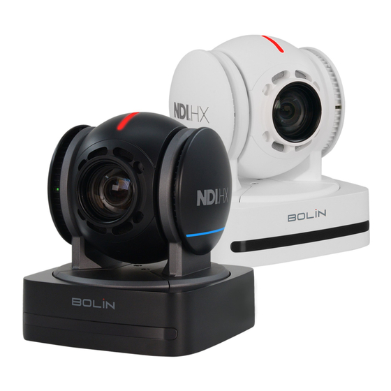
The product this manual refers to is covered by the Waste Electrical & Electronic Equipment (WEEE) Directive and must be disposed of in a responsible manner. What's In The Box N2 Series Indoor PTZ Camera (N2-220X) IR Remote Controller (VCC-RC-2) USB to 3.5mm Audio Jack Adapter (VCC-UA35IO) -
Page 5: Optional Accessories
Overview This user guide will provide users of the N2-220X indoor PTZ cameras with in-depth knowledge of the various features and functions of the camera and how it can be utilized. Functions limited to a specific camera model will be noted as such in the various sections. - Page 6 Features Sony 1/2.8 Inch CMOS sensor, Effective pixel number: 2.13 Megapixels. Resolution: Up to 1920×1080p60/50/30/25fps. Color Space supports YUV (YCbCr) and RGB. IP Resolution: Up to 1080P60. 20X optical and 16X digital zoom. 3G-SDI video output HDMI1.4 -Type A and USB 2.0 - Type C. On screen display (OSD), WDR On/Off, Day/Night mode On/Off, Contrast, Color Hue, Gamma (0 to 4) and High Sensitivity.
-
Page 7: Power Options
Quick Start Guide The N2-220X Indoor PTZ Camera has multiple connection options for video output, power input, control input, audio input and output, and synchronization. You can choose the Supports NDI® HX3 and are fully compatible with NDI-enabled hardware and software. -
Page 8: Video Output
Use only the 12V DC power adapter (JEITA type4) provided with the unit. (Do not use any other DC power adapter.) POE+ (IEEE802.3at) is supported for powering the camera. NOTE: Verify that the POE+ power source is sufficient for the camera’s full operation. The camera will auto-pan, tilt, and scan upon DC power connection. Network This camera offers a variety of functionalities via a network connection. -
Page 9: Control Input
2. Open an HTML5-enabled web browser on a computer and enter the IP address of the camera. By default, the camera is set to 192.168.0.13. The IP address can also be located under the “Status” menu of the camera’s On-Screen Display (OSD) or by using Bolin Technology’s IPC Search Tool in the Download Center. - Page 10 Functions of the IR Controller: 1. Menu - On-Screen Display (OSD) Toggle 2. IR ID Selector - Select which IR Channel (Camera) to be controlled 3. AI Function Buttons - Disabled 4. Buttons 1-9 - Used to set & recall corresponding presets. (See #6 to set a preset and #16 to erase a preset) 5.
- Page 11 NOTE: Any DIP Switch changes should be done with the camera off. RS-422 Serial Commands (VISCA) The camera is equipped with an RS-422 port, which facilitates VISCA control over serial commands. This RS-422 port is also compatible with RS-485. The camera can be connected via a serial connection to a PTZ controller or a computer.
- Page 12 Use RS-422 (VISCA) / RS485 (PELCO P/D) For camera operations, the RS-422/485 port can be utilized to connect controllers, such as a joystick keyboard or a PC station. This allows for the effortless management of pan, tilt, and zoom functions, as well as access to all preset functions using the controller’s buttons. To operate a PC station, it is essential to have a software application that is compatible with this unit.
- Page 13 VISCA (Non-Sony) Keyboard RS422 Connection Guide for Establishing RS422 Connection and Daisy Chain Configuration for Multiple Cameras with a Non-Sony Controller: The included extension cables, along with the RJ45 to RS422 Phoenix connector adapter, should be utilized to establish an RS422 connection for the control device.
- Page 14 PELCO P/D Keyboard RS485 Connection Important: Utilize RS422 ports when establishing an RS485 connection. Only employ TX+ and TX- for RS485 connections. • Set the RS422 control method using the OSD menu or Web interface. • Set the camera ID on the OSD menu using the remote controller. •...
- Page 15 The extension cables that are provided, along with the RJ45 to RS422 Phoenix connector adapter, should be utilized to establish an RS422 connection for the control device. Alternatively, you can establish an RS485 connection by directly connecting the camera and the controller using a CAT5/6 T-568B Standard Ethernet cable.
-
Page 16: Visca Over Ip
VISCA over IP Using VISCA over IP allows users to control the camera from anywhere that is on the same LAN as the camera. It involves connecting the PTZ camera to a network switch. The steps are as follows: 1. Connect the camera to the network by inserting one end of a CAT6 cable into the 10/100/1000 LAN port of the camera and the other end into a network switch. -
Page 17: Onvif Protocol
NOTE: Factory-Default Camera Settings for control of VISCA over IP Static IP Address: 192.168.0.13 Subnet Mask: 255.255.255.0 Gateway: 192.168.0.1 VISCA over IP Control Port: 52381 To change these settings, refer to the Web Interface Configuration section of this guide. NOTE: The VISCA over IP port of the controller MUST be set to 52381 to communicate with and control the camera. ONVIF Protocol Can be easily integrated with other ONVIF compliant devices and systems. -
Page 18: Tally Light
Tally Light Tally Light GPI I/O connection The camera is equipped with two tally lights, serving as visual indicators. When illuminated, these lights signal that the camera is actively operational. One front Tally light improves visibility, and an additional tally light positioned behind the camera block improves rear visibility. To activate the camera's Tally Light function, you need a video switch and a keyboard (not included). -
Page 19: Web Interface Configuration
2. GPI I/O Output Mode for Tally Signal Sent by Keyboard Controller: a. Connect the camera to the keyboard using a standard RS-422 control cable. b. Navigate to KEYBOARD SETTING > GPI I/O > Setting, and switch it to Output mode. Exit directly to the home menu. c. -
Page 20: Live View
Once connected to the network, the camera can be configured and controlled through the web interface on any web browser that supports HTML5. This next section will explain the various sections of the web interface and what they can do. LOGIN To log in to the web interface, first, make sure that the camera is connected to the network and that your computer is on the same subnet as the camera. - Page 21 See a preview of the video output (NOTE: This feed will be delayed by 1–2 seconds.) Adjust and control PTZ functions Set and recall camera presets Adjusting and Controlling PTZ Functions On the “Live View” page, the user will observe a “Menu” icon situated at the bottom right of the live view image. Additionally, on the right side of the page, there are “Pan/Tilt Controls”.
-
Page 22: Fast Settings
Adjusting OSD Menu Settings from the Web Interface The OSD Menu settings can be accessed and adjusted from the Web Interface. On the “Live View” page, locate and click the “Menu” icon situated at the bottom right of the live view image to display the OSD menu. The user can navigate through these settings using the arrows under “Pan/Tilt Control”. The middle button is used to select, and the right arrow button is used to modify the setting. -
Page 23: Camera Settings
CAMERA SETTINGS CAMERA - This page consists of 3 tabs: Codec, Digital Output, and OSD. CODEC: From the Codec tab, users can configure the video streams to meet their requirements. The various settings and their functions are described below. - Page 24 OUTPUT: Here you can select the HDMI/ SDI video resolution output of the camera. OVERLAY Steps to implement an on-screen overlay: 1. Begin by adding text to the title bar, such as in ‘1-Title’, then click on the checkbox located furthest to the left (which will turn red with a white check mark) to display it on the live feed image.
- Page 25 that this image will only be displayed on the user’s main stream. IMAGE - IMAGE SETTINGS The image settings page consists of 6 tabs. Exposure, White Balance, Picture, Picture 2, Scene, and Lens. The EXPOSURE tab lets you set the exposure to: You can choose from the following modes: Full Auto, Manual, Shutter Priority, or Iris Priority. Please be aware that the parameters (such as Iris, Shutter Speed, and others) will automatically adjust according to the selected mode.
- Page 26 PICTURE 1: The settings include adjustments for Sharpness and Hue, as well as 2D and 3D Noise Reduction. There are also options to turn on or off features such as Flip, Mirror, Portrait, Backlight Compensation, and De-Flicker. The De-Flicker feature has settings for Off, 50Hz, and 60Hz. PICTURE 2: The settings allow for adjustments to the Gamma level, Contrast, Saturation, and Brightness.
- Page 27 SCENE: The settings include Scene presets with options for Default, Brightness, Clear, and Soft. There are Defog options with settings for Off, Auto, Manual, and Low. The Day/Night Mode has settings for Day, Night, and Auto, with sensitivity adjustments available for Low, Middle, and High levels. LENS: The settings include a Mode option for Auto, Manual, and One Push White Balance.
-
Page 28: Audio Settings
COLOR MATRIX: You can emphasize or weaken a specific color region while keeping the white convergence point unchanged. AUDIO - AUDIO SETTINGS... -
Page 29: Network Settings
Audio Input: Mute On/Off Audio Compression setting: AAC, G711a or G711u Bit Rate selection: 30K, 40K, 48K, 64K, 96K,128K Sample Rate setting: 16K, 32K, 44.1K, and 48K Input Volume control: slider from 0 to 100. Apply settings or reset to Default settings. NOTE: When the audio compression is set to G711a or G711u, the Bit Rate is locked to 64K and Sample Rate to 8K. - Page 30 The NETWORK tab provides the following configuration options: Pattern: Choose between DHCP, which allows the camera to automatically receive an IP address from the DHCP server, or Static, which allows you to manually input an IP address. IP Address: Use the assigned IP address or manually enter a static IP address. Subnet Mask: This is determined based on the range of the IP address class.
- Page 31 The PORT tab provides the following configuration options: TCP Port: Adjustable within a range of 1 to 65535. UDP Port: Adjustable within a range of 1 to 65535. RTSP Port: Defaulted to 554. RTSP is the protocol used for real-time video playback over the network, compatible with software like VLC Media Player.
- Page 32 Navigate to the RTMP tab to stream or publish a video to a CDN (Content Delivery Network) or a cloud platform. You can obtain the URL stream and key number from an online platform such as YouTube or Twitch, usually found under Stream Settings in YouTube Studio. Stream Type: Choose between the Main or Sub Stream.
- Page 33 3. Enter the FTP server’s port number into the ‘Server Port’ field. This should match the port configured on the FTP server, typically port 21. 4. Enter the FTP server’s username and password into the ‘Server Username’ and ‘Server Password’ fields, respectively. These credentials should match those configured on the FTP server.
- Page 34 Stream Type: Main and Sub Stream options SRT Streaming: Enable: Caller, Listener and Rendezvous selection. Caller: Set the source or destination device as the initiator of the SRT streaming session. Note, Caller mode only is sent to one receiver. 1. The Caller device must know the IP address and port number of the Listener device. 2.
-
Page 35: System Settings
NDI Encoder Enable: Enable or disable the NDI encoder. When enabled, the camera will stream video using the NDI protocol. NDI Name: Enter a name for your NDI HX3 Indoor Camera. This name will be used to identify the camera on the network. Channel Name: Enter a name for the channel. - Page 36 The Device tab provides fundamental details about the PTZ camera. Device Name: You can assign a unique name to the camera and confirm by clicking Apply. You may need to share the information from this tab with the Bolin technical team, which includes the Model number, Serial number, IP Encoder Version, and AF Version.
- Page 37 Network Time Sync: Check this box to input the time from a Sync Server. Time Sync Server: Sync Server URL address. Port: Enter a Port number. Refresh: Select a refresh rate time:10 Min, 30 Min, 1 Hour, 1 Day. Apply settings or click on Default to reset. MAINTENANCE Firmware Update: Click on the File Browser section and select the Firmware file update.
-
Page 38: User Management
The User tab, located under the System section, is where you can manage operators who have access to the camera. Note that operators do not have the same level of access to system settings as administrators. User Management: 1. The ‘Add users’ button needs to be clicked. 2. - Page 39 N2-220X User Guide www.bolintechnology.com Bolin Technology...
Need help?
Do you have a question about the N2-220X and is the answer not in the manual?
Questions and answers