Advertisement
Quick Links
Network Camera
Quick Start Guide
1
Warning and Caution
■ Please read this instruction carefully before operating the unit and keep
it for further reference.
■ All the examples and pictures used here are for reference only.
■ The contents of this manual are subject to change without notice.
■ If the product does not work properly, please contact your dealer or the
nearest service center. Never attempt to disassemble the camera yourself.
(We shall not be responsible for any problems caused by unauthorized
repair or maintenance.)
■ Do not allow water or liquid intrusion into the camera.
■ In the use of the product, you must be strict compliance with the electrical
safety regulations of the nation and region. When the product is mounted on
wall or ceiling, the device shall be firmly fixed.
■ Do not use camera beyond specified voltage range.
■ The product must be grounded to reduce the risk of electric shock.
■ Do not drop the camera or subject it to physical shock.
■ Avoid touching the camera lens.
■ If cleaning is necessary, please use clean cloth to wipe it gently.
■ Do not aim the camera at the sun or extra bright place.
■ Do not place the camera in extremely hot, cold, dusty or damp locations, and do
not expose it to high electromagnetic radiation.
■ To avoid heat accumulation, good ventilation is required for operating
environment.
2
Package
Tapping screw×4
Camera
Quick start guide
CVBS&DC
CD
Drill template
Screwdriver
3
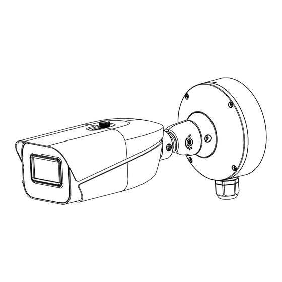
Overview
10-pin Interface:
PWR
GND
12V+
DC12V Output
(200mA)
Reset: Press Reset button for about 10s when the camera is powering on to restore the
default settings.
►
Connecting Alarm Input/Output
Alarm Input
Alarm Output
IPC
× 4
Plastic plug
Contact parameters of Relay:
Contact Load: resistive: 1A 125VAC/24VDC
Terminal for 12VD
Max. Voltage: 30VDC/125VAC
IN cable
C/24VAC power
Max. Current: 1A
Min. Current & Voltage: 10mA, 5VDC
10-pin Interface
Network Interface
Audio In Interface
SD card slot
Zoom-
Reset
CVBS&DC
Zoom+
IN Interface
ALM-I
RS 485
VO
GND
CVBS
D-
D+
GND
INA
CVBS Output
RS 485 Interface
Alarm Input
ALARM-INA
3
IPC
Sensor
ALARM-GND
4
Relay
ALARM-OPEN
ALARM-COM
+
DC
-
4
Installation
Please make sure that the wall or ceiling is strong enough to
withstand 3 times the weight of the camera. Please install the
camera in the dry environment.
① Install a micro SD card as shown below.
Audio Out Interface
DC12V Power
Interface
AC24V Power
Interface
ALM-O
NO
COM
Alarm Output
② Unscrew the mounting base of the camera and then remove the
junction box.
③ Drill the screw holes and the cable hole according to the drill
template.
Alarm output
Device
TF
63.6
(mm)
Ø155.4
Mounting
63.6
Base
4-Ø7.0
Ø90.0
Advertisement

Related Manuals for TVT TD-9444M3


Summary of Contents for TVT TD-9444M3
- Page 1 Overview Installation Network Camera Quick Start Guide Please make sure that the wall or ceiling is strong enough to 10-pin Interface withstand 3 times the weight of the camera. Please install the Network Interface camera in the dry environment. Audio In Interface ①...
- Page 2 ④ Mount the junction box to the wall. ⑦ Bracket adjustment-Before adjustment, preview the image of Device Network Search Immediate Refresh About the camera on a monitor and then loosen the lock screws to adjust Device Name Device Type Product Model IP Address Http Port Data Port...
Need help?
Do you have a question about the TD-9444M3 and is the answer not in the manual?
Questions and answers