Table of Contents
Advertisement
Quick Links
Network Camera
Quick Start Guide
■ Please read this instruction carefully before using the product and
keep it for further reference.
■ All the examples and pictures used here are for reference only.
■ The contents of this manual are subject to change without notice.
1
Warning and Caution
■ If the product does not work properly, please contact your dealer
or the nearest service center. Never attempt to disassemble the
camera yourself. (We shall not be responsible for any problems
caused by unauthorized repair or maintenance.)
■ Keep away from liquid while in use.
■ In the use of the product, you must be strict compliance with the
electrical safety regulations of the nation and region. When the
product is mounted on wall, the device shall be firmly fixed.
■ Do not use camera beyond specified voltage range.
■ Do not drop the camera or subject it to physical shock.
■ Avoid touching the camera lens.
■ If cleaning is necessary, please use clean cloth to wipe it gently.
If the device will not be used for a long time, please cover the lens
cap to protect the device from dirt.
■ Do not aim the camera at the sun or extra bright place.
■ Do not place the camera in extremely hot, cold (the operating
temperature shall be -10˚C~45˚C), dusty or damp locations, and do
not expose it to high electromagnetic radiation.
■ To avoid heat accumulation, good ventilation is required for
operating environment.
2
Package
Quick start guide
Camera
Drill template
2 tapping screws
3
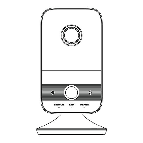
Overview
1
I
ALARM
G
O
DC12V
LAN
2
RST
3
4
STATUS
LINK ALARM
5
6
8
7
9
1
Lens
2
10
IR LED ( ON: visible)
3
11
Microphone
4
12
PIR (Passive Infrared) sensor
5
13
Power indicator
6
Network indicator
14
15
7
Alarm indicator
8
Light sensing
16
● Alarm Connections:
: Alarm output interface; G: Grounding
I: Alarm input interface;
O
Alarm input: Connect the cables of the sensor to I and G interfaces.
Alarm output: Connect the cables of the alarm output device to O and G
interfaces.
● Indicators
Power indicator: Green: the camera is started successfully.
Network indicator: Flashing blue: the camera is connected
to the wired network successfully.
CD
Alarm indicator: Red: alarms are triggered.
● Reset
2 plastic plugs
Press RST about 10s when the camera is powered on to
restore the default settings.
● WPS
WPS (Wi-Fi Protected Setup): Press the WPS button on the router
and then press the RST button on the camera within 120s to quickly
connect the Wi-Fi. Pressing the RST button on the camera and then
pressing the WPS button on the router will work as well. The red
14
alarm indicator will flash if the Wi-Fi is connected.
9
10
● 3-axis Bracket Adjustment
11
12
13
15
16
Ethernet connector & PoE
Speaker
4
Alarm I/G/O
Installation
Power connector
Reset or WPS
The camera can be placed on the desktop or installed on the wall.
Please make sure the wall is strong enough to withstand 3 times the
Micro SD card slot
weight of the camera. The steps of wall mounting are as follows.
3-axis bracket
① Attach the drill template to the place where you want to fix the
Mounting base
camera. Then drill the screw holes on the wall according to the drill
template.
② Peel off the drill template and then insert the plastic plugs and
screws into the screw holes. Please leave a little clearance between
the wall and the screws.
230°
71°
Advertisement
Table of Contents

Related Manuals for TVT TD-C12


Summary of Contents for TVT TD-C12
-
Page 1: Network Camera
● Indicators Network Camera Power indicator: Green: the camera is started successfully. Network indicator: Flashing blue: the camera is connected Quick Start Guide Quick start guide to the wired network successfully. Camera Alarm indicator: Red: alarms are triggered. ● Reset ■... - Page 2 ● Access the Camera Through Wi-Fi Plastic plug Network Connection A: You can quickly connect Wi-Fi through WPS function (See 3 Overview--WPS for more details). ● Access the Camera Through the Wired Network 34.5 B. You can also follow the steps below to connect Wi-Fi. Screw ①...
Need help?
Do you have a question about the TD-C12 and is the answer not in the manual?
Questions and answers