Bender ATICS-2 DIO Series Manual
Automatic transfer switching devices for safety power supplies
Hide thumbs
Also See for ATICS-2 DIO Series:
- Quick start manual (21 pages) ,
- Quick start manual (9 pages)
Advertisement
Quick Links
Manual EN
ATICS-2-...-DIO, ATICS-4-...-DIO
ATICS-2-63A-DIO, ATICS-2-80A-DIO
ATICS-4-80A-DIO, ATICS-4-125A-DIO, ATICS-4-160A-DIO
Automatic transfer switching devices for safety power supplies
Software version: D333 V1.3x, D334 V1.3x, D335 V1.0
ATICS-2-DIO_D00080_05_M_XXEN / 04.2024
Advertisement

Related Manuals for Bender ATICS-2 DIO Series


Summary of Contents for Bender ATICS-2 DIO Series
- Page 1 Manual EN ATICS-2-…-DIO, ATICS-4-…-DIO ATICS-2-63A-DIO, ATICS-2-80A-DIO ATICS-4-80A-DIO, ATICS-4-125A-DIO, ATICS-4-160A-DIO Automatic transfer switching devices for safety power supplies Software version: D333 V1.3x, D334 V1.3x, D335 V1.0 ATICS-2-DIO_D00080_05_M_XXEN / 04.2024...
- Page 2 ATICS-2-DIO_D00080_05_M_XXEN / 04.2024...
- Page 3 Indication of important instructions and information...............6 Signs and symbols............................6 Service and Support............................6 Training courses and seminars........................7 Delivery conditions............................7 Inspection, transport and storage......................7 Warranty and liability.............................7 Disposal of Bender devices..........................8 Safety..........................9 Intended use........................10 System description......................11 Properties................................. 11 4.1.1 Product description............................11 4.1.2...
- Page 4 Table of contents 5.1.4 DIN rail mounting............................23 5.1.5 Screw mounting on plate.......................... 24 Connection...............................24 5.2.1 Short-circuit protection..........................24 5.2.2 Connecting ATICS® safely...........................25 5.2.3 ATICS® basic configuration........................28 5.2.4 Connection example: ATICS® with bypass switch................30 5.2.5 Instructions for connection........................32 5.2.6 Fastening, inserting and securing connections.................32 Other functions..............................
- Page 5 ATICS-2-…-DIO, ATICS-4-…-DIO 8.3.6 Menu 6: Dig. input............................70 8.3.7 Menu 7: Info..............................70 Troubleshooting......................71 Fault and alarm messages......................... 71 9.1.1 Plain text messages............................71 9.1.2 Messages with error code or service code..................72 Frequently asked questions........................73 Periodic verification and service...................75 10.1 Periodic verification............................75 10.2...
- Page 6 Temperature range Recycling RoHS directives Service and Support Information and contact details about customer service, repair service or field service for Bender devices are available on the following website: Fast assistance | Bender GmbH & Co. KG. ATICS-2-DIO_D00080_05_M_XXEN / 04.2024...
- Page 7 Regular face-to-face or online seminars for customers and other interested parties: www.bender.de > know-how > seminars. Delivery conditions The conditions of sale and delivery set out by Bender GmbH & Co. KG apply. These can be obtained in printed or electronic format. The following applies to software products: "Software clause in respect of the licensing of standard software as part of deliveries,...
- Page 8 General information Disposal of Bender devices Abide by the national regulations and laws governing the disposal of this device. For more information on the disposal of Bender devices, refer to www.bender.de > service & support. ATICS-2-DIO_D00080_05_M_XXEN / 04.2024...
- Page 9 The rules for working on electrical systems must be observed. Bender devices are designed and built in accordance with the state of the art and accepted rules in respect of technical safety. However, the use of such devices may introduce risks to the life and limb of the user or third parties and/or result in damage to Bender devices or other property.
- Page 10 Intended use Intended use Transfer switching devices are used everywhere there is dependence on high availability from the power supply. The ATICS® automatic transfer switching and monitoring device is intended for the application described in the chapter “System description”, page 11. When the preferred supply fails, the ATICS® automatically switches to the second supply.
- Page 11 ATICS-2-…-DIO, ATICS-4-…-DIO System description Properties 4.1.1 Product description The ATICS® automatic transfer switching devices provide all functions for changeover between two independent power supplies and for monitoring unearthed power supplies. The integration of both the electronic system and the switching elements in one flat, compact device reduces space requirements in the switchgear cabinet, minimises the amount of wiring, and reduces the fault probability.
- Page 12 System description 4.2.1 Product life-cycle management Safety must be guaranteed over the entire life cycle, from the time it is designed, developed, manufactured, commissioned, maintained to the time it is taken out of service. Responsibility during the life cycle: For detailed information refer to: •...
- Page 13 ATICS-2-…-DIO, ATICS-4-…-DIO ATICS® tasks • Two-pole changeover of the power supply • Voltage monitoring of the preferred supply (line 1) • Voltage monitoring of the second supply (line 2) • Voltage monitoring at the automatic transfer switching device output (line 3) •...
- Page 14 If the ATICS® detects a supply failure or a fault, an alarm appears on the LCD, the “ALARM” LED lights up, the alarm relay trips (if set) and this alarm is forwarded to other Bender devices (such as an alarm indicator and test combination) via the BMS bus.
- Page 15 ATICS-2-…-DIO, ATICS-4-…-DIO 4.5.1.1 Time diagram: Changeover between preferred and redundant line Time diagrams: Times are not shown to scale. Example: Line 1 is set as preferred line. Legend t(pulse) Pulse time: 15 … 30 ms t(0) Dead time t(on) Response delay ALARM failure voltage line 1 Measuring time: approx.
- Page 16 System description 4.5.1.2 Time diagram: Staggered switching on after complete power failure Switching on at staggered intervals after a complete power failure (no voltage on either of the power supplies) prevents all loads from being switched on at the same time. Switch ATICS®...
- Page 17 ATICS-2-…-DIO, ATICS-4-…-DIO 4.5.1.3 Time diagram: Changeover to generator mode ATICS-2-DIO_D00080_05_M_XXEN / 04.2024...
- Page 18 System description Legend t(pulse) Pulse time: 15 … 30 ms t(0) Dead time t(on) Response delay ALARM failure voltage line 1 | Measuring time: approx. 50 ms t(Start) Switch-on delay after complete power failure and restart of ATICS® | Measuring time: approx. 50 ms t(off) Delay on release ALARM failure voltage line 1 | Measuring time: approx.
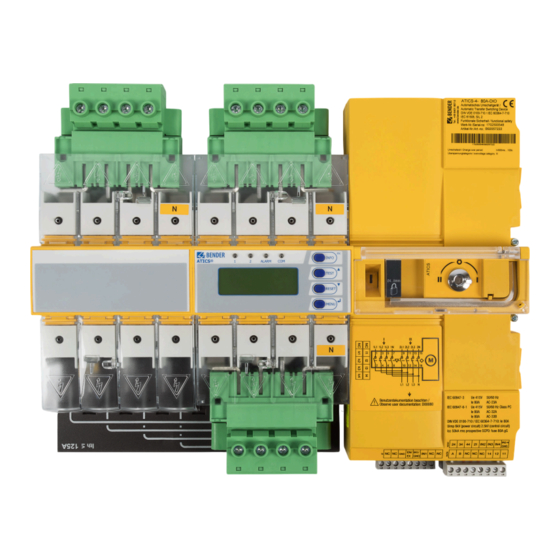
- Page 19 ATICS-2-…-DIO, ATICS-4-…-DIO ATICS-2-DIO front view Legend 1 Green plug connector for line 1 and line 2 2 Control buttons 3 Inspection window for switch position 4 Manual mode of the device, indicates the switch position 5 Allen key for manual mode 6 Transparent cover for changeover switch (manual mode), sealable 7 Wiring diagram for lines 1, 2 and 3 8 Three coded connector plugs...
- Page 20 System description ATICS-4-DIO front view Legend 1 Green plug connector for line 1 2 Green plug connector for line 2 3 Control buttons 4 Inspection window for switch position 5 Manual mode of the device, indicates the switch position 6 Allen key for manual mode 7 Transparent cover for changeover switch (manual mode), sealable 8 Wiring diagram for lines 1, 2 and 3 9 Three coded connector plugs...
- Page 21 ATICS-2-…-DIO, ATICS-4-…-DIO Mounting and connection DANGER Danger to life due to electric shock Touching live parts of the system carries the risk of electric shock. Before installing the device and prior to working on the device connections, make sure that the power supply is disconnected.
- Page 22 Mounting and connection 5.1.1 Dimension diagram ATICS-2-…-DIO Additional space required for auxiliary contact when using the bypass switch Rear view (dimensions for screw mounting on mounting plate) Cutout for terminal cover 5.1.2 Dimension diagram ATICS-4-…-DIO Additional space required for auxiliary contact when using the bypass switch Cutout to the terminal cover Dimensions for screw mounting on plate Additional space required for the connector plug of the measuring current transformer...
- Page 23 ATICS-2-…-DIO, ATICS-4-…-DIO 5.1.3 Removing terminal cover Push back the locking hook (B) in the middle of the top and bottom terminal cover (A) by using a screwdriver. Remove the terminal cover. 5.1.4 DIN rail mounting ADVICE Material damage due to loose screws If the screws are loose, ATICS®...
- Page 24 Mounting and connection 5.1.5 Screw mounting on plate • Observe dimension diagram of rear view. • Use M5 mounting screws. CAUTION Reduced voltage clearances caused by screw heads or washers Use mounting screws with flat screw heads and flat washers to provide for sufficient clearance to live conductors (voltage clearance).
- Page 25 ATICS-2-…-DIO, ATICS-4-…-DIO 5.2.2 Connecting ATICS® safely DANGER Danger to life due to electric shock! If any of the supplies are switched on, some of the system parts which are not yet fully installed may be live. Prevent unintended switch-on: Open the transparent cover. Wait until “manual mode”...
- Page 26 (short-circuit monitoring) grey GND, EN/EX Connection is intended only for ATICS-2-ISO-ES to connect ATICS-ES energy storage device or for Bender- internal purposes (12 V). In other cases the connection must not be used. IN1/GND, IN1 Digital input, configurable (see chapter “Settings menu 5: Dig.
- Page 27 ATICS-2-…-DIO, ATICS-4-…-DIO Anschlussklemmen ATICS-4-DIO Colour Terminal Description 1, 3, 5, 7 Connection line 1 (input line) 1L1, 1L2, 1L3, 1N 9, 11, 13, 15 Connection line 2 (input line) 2L1, 2L2, 2L3, 2N 10, 12, 14, 16 Connection line 3 (output line) L1, L2, L3, N GND, En/Ex Do not use, intended for future extensions.
- Page 28 Mounting and connection 5.2.3 ATICS® basic configuration WARNING Risk of destruction if connected incorrectly The terminals marked with “*” are intended for Bender-internal purposes only. If this is ignored, ATICS® may be damaged. Figure: ATICS-2-DIO basic configuration ATICS-2-DIO_D00080_05_M_XXEN / 04.2024...
- Page 29 ATICS-2-…-DIO, ATICS-4-…-DIO Figure 5-1: ATICS-4-DIO basic configuration ATICS-2-DIO_D00080_05_M_XXEN / 04.2024...
- Page 30 Connection example: ATICS® with bypass switch WARNING Risk of destruction if connected incorrectly The terminals marked with “*” are intended for Bender-internal purposes only. If this is ignored, ATICS® may be damaged. Figure: ATICS-2-DIO with bypass switch ATICS-2-DIO_D00080_05_M_XXEN / 04.2024...
- Page 31 ATICS-2-…-DIO, ATICS-4-…-DIO Figure: ATICS-4-DIO with bypass switch ATICS-2-DIO_D00080_05_M_XXEN / 04.2024...
- Page 32 The terminals A and B are available for connecting BMS-enabled devices. Alarm indicator and test combinations, alarm indicator and operator panels or other bus-enabled Bender devices can be connected. The bus line must be terminated at both ends with resistors (120 , 0.25 W). Please note the information in the “BMS bus”...
- Page 33 ATICS-2-…-DIO, ATICS-4-…-DIO ° ATICS-4-160A-DIO: 5 N m • Ensure that the lines are short-circuit and earth-fault proof! – For connecting the lines to the three connector plugs (C): • stripping length: 7 mm • tool: slotted screwdriver of 2.5 x 0.4 mm •...
- Page 34 Mounting and connection Enabling manual mode Variant A: Open the transparent cover. Set the digital input. “M/A” function must be set (see chapter “Settings menu 5: Dig. input”, page 63). Variant B: Place the handle on the Allen key, use the Allen key to switch over. 5.3.3 Lock ATICS®...
- Page 35 ATICS-2-…-DIO, ATICS-4-…-DIO Commissioning, settings and testing Design and installation 6.1.1 Safety advice Ensure that the displays work correctly MK… alarm indicator and test combinations, TM... alarm indicator and operator panels or BMS Ethernet gateways COM460…, which, together with ATICS®, are connected to a BMS bus must be provided with the latest operating software (e.g.
- Page 36 Commissioning, settings and testing This is achieved by entering the ATICS® device address in the alarm address table. If necessary, individual messages can also be programmed for channels 1, 2, 5, 7…11. No individual text may be programmed for channel 6. The failure of the other MK…/TM…/CP…...
- Page 37 ATICS-2-…-DIO, ATICS-4-…-DIO ATICS-4-DIO Entry in the menu 1. Description Operating message Alarm message Error channel Alarm/meas.values 1. Line 1: 228V Line 1 Voltage Voltage Phase seq. left, unbalance 2. Line 2: 183V Line 2 Voltage Voltage Phase seq. left, unbalance 3.
- Page 38 Commissioning, settings and testing Messages on the digital input The following operating and alarm messages may appear depending on the settings in chapter “Settings menu 5: Dig. input”, page 63: Menu Function of digital input Alarm on BMS bus BMS channel settings Digital input disabled No message...
- Page 39 ATICS-2-…-DIO, ATICS-4-…-DIO • The total off-time (from the point at which the fault occurs until the arc in the overcurrent protective device is cleared) must be less than the minimum delay for the changeover of the automatic transfer switching device. Setting: Response delay t(on) •...
- Page 40 Operation Operation Operating and display elements LED/Button Description LED “1” lights up: Line 1 is ready LED “2” lights up: Line 2 is ready LED “ALARM” lights up: Alarm message present LED “COM” flashes: Communication via BMS bus “INFO” Query standard information “ESC”...
- Page 41 ATICS-2-…-DIO, ATICS-4-…-DIO Quick reference guide 7.2.1 Display under normal operating conditions Line 1: Measured values of mains voltage and frequency Switch position of the automatic transfer switching device Line 2: Measured values of mains voltage and frequency Display of the load in the IT system in %. The maximum load current is adjustable.
- Page 42 Operation Press to display the current alarm: • Line 1: ALARM – xx = serial number of the displayed alarm – yy = number of pending messages • Line 2: Alarm status and alarm text Figure: Alarm message “Undervoltage” • Line 3: Measured value •...
- Page 43 ATICS-2-…-DIO, ATICS-4-…-DIO Menu item Function Reference 5. Test communication Communication test via the BMS bus. To do this, simulate an alarm and send an “Test menu 5: Test alarm message via the BMS bus. communication”, page 47 Test menus 2…4 are protected by a password (see chapter “Settings menu 10: Password”, page 68. Password protection is only effective if the password has been enabled.
- Page 44 Operation 7.2.3.1 Test menu 1: Autom. changeover Autom. changeover Test of the changeover function. The device switches to the redundant line. The changeover period t(1->2) is displayed. After the set time t(test) has elapsed, the device switches back to the preferred line. Cancel Return to test menu The date of the test is saved in the test logger to send a reminder for the next test once the test interval has...
- Page 45 ATICS-2-…-DIO, ATICS-4-…-DIO ADVICE Test is accidentally not completed If the test menu “Manual changeover” is left after switching over to the redundant line, then ATICS® remains in this switch position and in “TEST” mode. Wait until “Quit: RESET” appears on the display. Press the “RESET”...
- Page 46 Operation 7.2.3.4 Test menu 4: Generator Executing this function makes sense only when a generator is connected to the redundant line and the corresponding settings have been carried out (see chapter “Settings menu 1: Changeover”, page 59). To avoid voltage interruptions, in the test menu “Generator”, ATICS® does not switch to the redundant line. In order to test the generator and the changeover switch, select “Autom.
- Page 47 ATICS-2-…-DIO, ATICS-4-…-DIO 7.2.3.5 Test menu 5: Test communication Communication test via the BMS bus. In order to do this, a fault message is simulated. This alarm message is sent to evaluator devices (e.g. alarm indicator and operator panels, MK800, SMO…). Check that these devices are responding to the alarm message as requested.
- Page 48 Operation Menu item Function Reference 1. Alarm Reset alarm and fault messages on the device. “Reset menu 1: Alarm”, page 48 2. SwitchBackLock Disable the switch-back lock of the changeover function. The device switches “Reset menu 2: back to the redundant line. SwitchBackLock”, page 48 3.
- Page 49 ATICS-2-…-DIO, ATICS-4-…-DIO 7.2.4.3 Reset menu 3: Changeover Component failure possible with increasing service life! For operation according to IEC 61508-2, additional limit values are monitored (number of switching cycles, operating time, number of switching cycles in the event of a short circuit). If the set limit values are exceeded, the device displays a prewarning or an alarm. The alarm can be “deleted”...
- Page 50 Operation 7.2.4.4 Reset menu 4: Service alarm • Resetting the service prewarning suppresses the service prewarning until the next service appointment. • Resetting the service alarm sets the date for the next service appointment to “current date + service interval”. ATICS-2-DIO_D00080_05_M_XXEN / 04.2024...
- Page 51 Switching on and calling up the main menu When the device is connected to the power supply, the Bender logo appears on the display for approx. 3 seconds. If the device has been without power for several days, time and date must be readjusted.
- Page 52 Menu mode: Operation and setting Menu overview diagram The following diagram will help you to navigate through the menus: ATICS-2-DIO_D00080_05_M_XXEN / 04.2024...
- Page 53 ATICS-2-…-DIO, ATICS-4-…-DIO Function of the main menu Menu item Function Reference Exit Exit menu mode 1. Alarm/meas.values Display saved status messages, alarm messages and measured values “Menu 1: Alarm/ meas.values”, page 53 2. Changeover Display information on the changeover function (number, test) “Menu 2: Changeover”, page 56 3.
- Page 54 Menu mode: Operation and setting Menu Description Alarm digital input 2 Dig. input: (see chapter “Settings menu 5: Dig. input”, page 63) Alarm digital input 3 Dig. input: (see chapter “Settings menu 5: Dig. input”, page 63) Alarm digital input 4 Dig.
- Page 55 ATICS-2-…-DIO, ATICS-4-…-DIO Menu Description U1(3-N): 230V Line 1: Measured value mains voltage phase L3 to neutral conductor N U1(1-2): 400V Line 1: Measured values phase L1 to phase L2 U1(2-3): 400V Line 1: Measured values mains voltage phase L2 to phase L3 U1(3-1): 400V Line 1: Measured values mains voltage phase L3 to phase L1 Line 1: 50.0Hz...
- Page 56 Menu mode: Operation and setting Menu Description Return transfer delay time is enabled, seconds counting backwards or switchback lock enabled t(2->1): -- All messages (except measured value frequency) are also present on the BMS bus (see chapter “Messages with error code or service code”, page 72). 8.3.2 Menu 2: Changeover Display information on the changeover function (number, test).
- Page 57 (in this case: [4/1]). Channel 1 means that the first digital input has been changed. Please contact the Bender service and provide the identification number if the modification led to an undesirable behaviour of the device.
- Page 58 Adjustable in each case: change password, enable/disable password Password”, page 68 11. Service Only intended for settings by authorised Bender service personnel. Call up “Settings menu 11: information about the device status and make settings for specific operating Service”, page 69 conditions.
- Page 59 ATICS-2-…-DIO, ATICS-4-…-DIO 8.3.4.1 Settings menu 1: Changeover The times set in this menu determine the timing of a changeover. Observe also the time diagrams in chapter “The automatic transfer switching device”, page 13. Menu item Function Exit Go up one menu level 1.
- Page 60 Menu mode: Operation and setting Menu item Function 9. Reminder Prewarning time for test interval (set value smaller than test interval): Setting range: off, 1…60 days Resolution of setting: 1 day 10. Serviceinterv. Service interval: Setting range: off, 6…48 months Resolution of setting: 6 months 11.
- Page 61 Go up one menu level 1. Mode Current monitoring enabled No current monitoring 2. Current transformer STW3 Bender measuring current transformer STW3 STW4 Bender measuring current transformer STW4 3. CT monitoring CT connection monitoring enabled CT connection monitoring disabled Note: External interference from loads can cause false tripping. In this case, the function has to be disabled.
- Page 62 Menu mode: Operation and setting Figure: Configure one current transformer Figure: Configure all four current transformers 8.3.4.4 Settings menu 4: Relay In this menu, you can adjust settings for the mode of operation and function of the relay output (alarm relay). These functions can be set: alarm message (“ALARM”), operating message (“Active”), generator start (“GenSt”, only for relay 1).
- Page 63 ATICS-2-…-DIO, ATICS-4-…-DIO Adjusting the settings: Menu Description Exit Go up one menu level 1. Function ALARM Relay switches if at least one of the following menus 3…9 is set to “on” and the corresponding alarm message appears. Active Relay switches if at least one of the following menus 3…9 is set to “on” and the corresponding alarm message does not appear (operating message).
- Page 64 Menu mode: Operation and setting selected function is carried out when there are 0 volts there. It is for this reason that you should always set unused digital inputs to “off”. By selecting the function of the digital input, the recommended response value is automatically adjusted: –...
- Page 65 ATICS-2-…-DIO, ATICS-4-…-DIO Menu Description 4. t(off) Delay on release: Setting range: 100 ms…100 s Resolution of setting: starting at 50 ms The common alarm for the digital inputs 2…4 is signalled on channel 12 of the BMS bus. If one of these digital inputs is set to “ALARM”...
- Page 66 Menu mode: Operation and setting Data logger Description 4. U2(1-N) Line 2: Measured value mains voltage phase L1 to neutral conductor N 5. U2(2-N) Line 2: Measured value mains voltage phase L2 to neutral conductor N 6. U2(3-N) Line 2: Measured value mains voltage phase L3 to neutral conductor N 7.
- Page 67 ATICS-2-…-DIO, ATICS-4-…-DIO Menu Description 3. Delete Delete Clear data logger. Cancel Do not clear data logger. 8.3.4.7 Settings menu 7: Language Select the language for the menus and the messages to be displayed (alarm and operating messages) of the device. Menu Description Exit...
- Page 68 Menu mode: Operation and setting 8.3.4.9 Settings menu 9: Clock Time and date are required for displays in the “History/Loggers” menu. The time setting is synchronised via the BMS bus. The device with address 1 (MK…/TM…/CP…) synchronises all other devices every hour. The time setting for the ATICS®...
- Page 69 8.3.4.11 Settings menu 11: Service The service menu is intended for settings by authorised Bender service personnel. It is only accessible to the Bender service. In the service menu, information about the device status can be called up and settings for specific operating conditions can be made.
- Page 70 Date, time Line 3: Address set on the BMS bus Line 4: Serial number of the device Line 5…6: Software versions of the four controllers of the device … Bender address, website … Exit. Exit standard information. ATICS-2-DIO_D00080_05_M_XXEN / 04.2024...
- Page 71 “Settings menu 8: Interface”, page 67. Service by __ (date) Reminder for next service • Schedule appointment with the Bender service. Functional test by __ Reminder for next test • Schedule appointment for next test.
- Page 72 Changeover due to overcurrent or short circuit • Have qualified personnel assess the short-circuit detected. These changeovers reduce the life of load. Contact the Bender service. Alarm can the device. Currents exceeding 130 A or 250 A be acknowledged (see chapter “Reset menu 3: are considered to be overcurrents or short-circuit Changeover”, page 49)
- Page 73 Have the article and serial number of the device at hand. Contact the Bender service and state the type of error and the three-digit error code. Frequently asked questions A series of clicks is always heard around noon. What does that mean? ATICS®...
- Page 74 Why does writing back reports/backups lead to error messages? Like many Bender devices, ATICS® can be monitored and configured by means of a Bender gateway CP700, COM46x…, etc. The gateways are operated via a web user interface that is displayed using an internet browser.
- Page 75 Periodic verification and service 10.1 Periodic verification The use of Bender products ensures protective measures against certain hazards when operating electrical systems. The corresponding legal requirements are defined in the Ordinance on Industrial Safety and Health (BetrSichV) and the supplementary Technical Rules (TRBS): Every company is obliged to draw up a risk assessment for its work equipment (electrical systems and equipment).
- Page 76 Periodic verification and service 10.4 Operation with bypass switch The ATICS-BP-… bypass switch enables a parallel supply of line 3. Without interrupting the voltage on line 3, ATICS® can be switched or exchanged as desired. The green indicator indicates position 1 of the ATICS® device, which at the same time indicates that the bypass switch can be operated.
- Page 77 ATICS-2-…-DIO, ATICS-4-…-DIO WARNING Electric shock Mains voltage is present at the contacts of lines 1, 2 and 3, which causes an electric shock if touched. Only touch the insulated part of the connector. 10.5 Replacing ATICS® The plug connectors make it easy to replace the device if •...
- Page 78 Periodic verification and service Removing ATICS® in case of DIN rail mounting Undo screws (D). Remove lower and upper terminal covers (A) by using a screwdriver to push back the locking hook (B) located approximately in the middle of the cover in each case. ATICS-2-DIO: Use a screwdriver to pull the lower yellow slide lock (C) downwards and raise ATICS®...
- Page 79 ATICS-2-…-DIO, ATICS-4-…-DIO Removing ATICS® in case of screw mounting Remove lower and upper terminal covers (A) by using a screwdriver to push back the locking hook (B) in the middle of each cover. Undo the Allen screws of the terminals (C). Remove the green plug connectors (D) at top and bottom.
- Page 80 Technical data Technical data 11.1 Technical data ATICS-…-DIO Insulation coordination acc. to IEC 60664-1/IEC 60664-3 Overvoltage category Pollution degree outside, inside Rated insulation voltage ATICS-2-DIO/ATICS-4-DIO 250 V / 400 V Protective separation between Line 1 – Line 2; Line 1, 2, 3 – RS-485; Line 1, 2, 3 –...
- Page 81 ATICS-2-…-DIO, ATICS-4-…-DIO Display range measured value ATICS-2-DIO 20…276 V Display range measured value ATICS-4-DIO 20…520 V Operating uncertainty ±1 % Changeover period t < 500 ms…100 s Current monitoring (output current) Measuring current transformers STW3, STW4 Measuring range I (TRMS) STW3: 0…>...
- Page 82 Technical data Relay output 1 Switching element 1 potential-free changeover contact Operating mode adjustable n/o or n/c operation Adjustable function see “Settings menu 4: Relay ”, page 62 Electrical endurance under rated operating conditions 10,000 cycles Contact data according to IEC 61810 Rated operational current AC (resistive load, cos φ...
- Page 83 ATICS-2-…-DIO, ATICS-4-…-DIO Environment/EMC EN 61326 (see CE declaration) Classification of climatic conditions acc. to IEC 60721 Stationary use (IEC 60721-3-3) 3K22 Transport (IEC 60721-3-2) 2K11 Long-term storage (IEC 60721-3-1) 1K22 Operating temperature −25…+55 °C Classification of mechanical conditions acc. to IEC 60721 Stationary use (IEC 60721-3-3) 3M11 Transport (IEC 60721-3-2)
- Page 84 Technical data Other Operating mode continuous operation Mounting display-oriented For use at altitudes up to 2000 m AMSL Protection class Class I Protection class LCD under foil (DIN EN 60529) IP40 Enclosure material polycarbonate Flammability class UL 94 V-0 DIN rail mounting acc.
- Page 85 ATICS-2-…-DIO, ATICS-4-…-DIO 11.2 TÜV test report according to VDE 0100 Part 710 ATICS-2-DIO_D00080_05_M_XXEN / 04.2024...
- Page 86 Technical data 11.3 TÜV certificate regarding functional safety ATICS-2-DIO_D00080_05_M_XXEN / 04.2024...
- Page 87 • DIN EN 61558-1/Berichtigung 2 (VDE 0570-1/Amendment 2):2008-12 • DIN EN 61558-1/A1 (VDE 0570-1/A1):2009-11 The standards marked with * were part of the test conducted by TÜV Süd. The EU Declaration of Conformity is available at the following Internet address: bender.de/fileadmin/content/Products/CE/CEKO_Atics.pdf 11.5 Ordering information ATICS®-…-DIO Variants ATICS®-…-DIO 2-pole...
- Page 88 Technical data Type Version Rated operational Scope of delivery Art. No. current I ATICS-BP-2-80A-SET Bypass switch set AC 80 A Bridge, terminal cover, auxiliary contacts, B92057253 LEDs green/red ATICS®-…-DIO 4-pole Type Version Rated operational Scope of delivery Art. No. current I ATICS-4-80A-DIO 4-pole AC 80 A...
- Page 89 ATICS-2-…-DIO, ATICS-4-…-DIO Type Description Art. No. Manual MK800… COMTRAXX® MK800 dis- D00053 continued Optional Accessories Type Description Art. No. STW3 Measuring current transformer (short-circuit monitoring) for ATICS® < 100 A B98021000 STW4 Measuring current transformer (short-circuit monitoring) for ATICS® < 100 A B98021001 11.6 Additional documents...
- Page 90 Alle Rechte vorbehalten. 35305 Grünberg Nachdruck und Vervielfältigung nur mit Germany Genehmigung des Herausgebers. © Bender GmbH & Co. KG, Germany Subject to change! The specified Tel.: +49 6401 807-0 All rights reserved. standards take into account the edition info@bender.de Reprinting and duplicating only with valid until 04.2024 unless otherwise...
Need help?
Do you have a question about the ATICS-2 DIO Series and is the answer not in the manual?
Questions and answers