Bender ATICS-4-160A-DIO Manuals
Manuals and User Guides for Bender ATICS-4-160A-DIO. We have 5 Bender ATICS-4-160A-DIO manuals available for free PDF download: Manual, Quick Start Manual

Bender ATICS-4-160A-DIO Manual (112 pages)
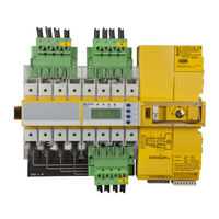
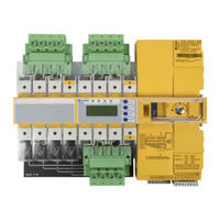
Automatic transfer switching devices for safety power supplies
Table of Contents
Advertisement
Bender ATICS-4-160A-DIO Manual (104 pages)
Automatic transfer switching devices for safety power supplies
Table of Contents
Bender ATICS-4-160A-DIO Manual (104 pages)
Brand: Bender
|
Category: Power Supply
|
Size: 4 MB
Table of Contents
Advertisement

Bender ATICS-4-160A-DIO Manual (90 pages)
Automatic transfer switching devices for safety power supplies

Bender ATICS-4-160A-DIO Quick Start Manual (12 pages)
Automatic transfer switching devices for safety power supplies