Table of Contents
Advertisement
Quick Links
Advertisement
Table of Contents

Related Manuals for Bender ATICS Series


Summary of Contents for Bender ATICS Series
- Page 1 ATICS-…-DIO ATICS-2-63A-DIO, ATICS-2-80A-DIO, ATICS-4-80A-DIO, ATICS-4-125A-DIO, ATICS-4-160A-DIO Automatic transfer switching devices for safety power supplies Software version: D333 V1.3x, D334 V1.3x, D335 V1.0 ATICS-DIO_D00080_03_M_XXEN / 04.2021 Manual EN...
- Page 2 Service und Support für Bender-Produkte Kundenservice Technische Unterstützung Carl-Benz-Strasse 8 • 35305 Grünberg • Germany Telefon: +49 6401 807-760 0700BenderHelp * Fax: +49 6401 807-629 E-Mail: support@bender-service.de 365 Tage von 07:00 - 20:00 Uhr (MEZ/UTC +1) * Festnetz dt. Telekom: Mo-Fr von 9-18 Uhr: 6,3 Cent / 30 Sek.; übrige Zeit: 6,3 Cent / Min.
-
Page 3: Table Of Contents
1.2.1 Signs and symbols ......................7 Training courses and seminars.................7 Delivery conditions .......................7 Inspection, transport and storage ................8 Warranty and liability....................8 Disposal of Bender devices ..................8 Safety ..........................8 General safety instructions ..................9 1.10 Device-specific safety instructions .................9 Intended use ..................11 System description ................. - Page 4 Mounting and connection ............. 27 Mounting ........................27 4.1.1 Dimension diagrams ....................27 4.1.2 Removing terminal cover ..................29 4.1.3 DIN rail mounting ...................... 29 4.1.4 Screw mounting on plate ..................30 Connection ........................30 4.2.1 Short-circuit protection ................... 30 4.2.2 Connecting the ATICS®...
- Page 5 ATICS-…-DIO 6.2.4.1 Reset menu 1: Alarm ......................57 6.2.4.2 Reset menu 2: Switch-Back Lock..................57 6.2.4.3 Reset menu 3: Changeover ....................57 6.2.4.4 Reset menu 4: Service alarm .....................58 Menu mode: Operation and setting ..........59 Switching on and calling up the main menu ..........59 Menu overview diagram ..................
- Page 6 Periodic verification and service ..........89 Periodic verification....................89 Maintenance ........................ 90 Cleaning ......................... 90 Operation with bypass switch ................90 Replacing the ATICS® ....................91 9.5.1 Removing the existing ATICS® ................92 9.5.2 Installing a new ATICS® .................... 94 Technical data ..................
-
Page 7: General Instructions
Training courses and seminars www.bender.de/en -> Know-how -> Seminars. Delivery conditions Bender sale and delivery conditions apply. These can be obtained from Bender in printed or electronic format. The following applies to software products: "Software clause in respect of the licensing of standard software as part of deliver-... -
Page 8: Inspection, Transport And Storage
• Non-observance of technical data. • Repairs carried out incorrectly. • Use of accessories and spare parts not recommended by Bender. • Catastrophes caused by external influences and force majeure. • Mounting and installation with device combinations not recommended by the manufacturer. -
Page 9: General Safety Instructions
General safety instructions Bender devices are designed and built in accordance with the state of the art and accepted rules in re- spect of technical safety. However, the use of such devices may introduce risks to the life and limb of the user or third parties and/or result in damage to Bender devices or other property. - Page 10 Intended use ATICS-DIO_D00080_03_M_XXEN / 04.2021...
-
Page 11: Intended Use
ATICS-…-DIO Intended use Transfer switching devices are used everywhere there is dependence on high availability from the pow- er supply. The ATICS® automatic transfer switching device is intended for the application described in the chapter „System description“ on p. 13. When the preferred supply fails, the ATICS® automatically switches to the second supply. - Page 12 System description ATICS-DIO_D00080_03_M_XXEN / 04.2021...
-
Page 13: System Description
ATICS-…-DIO System description Properties 3.1.1 Product description The ATICS® automatic transfer switching devices provide all functions for changeover between two in- dependent power supplies and for monitoring unearthed power supplies. The integration of both the electronic system and the switching elements in one flat, compact device reduces space requirements in the switchgear cabinet, minimises the amount of wiring, and reduces the fault probability. -
Page 14: Product Life-Cycle Management
Responsibility during the life cy- cle: Production Commissioning Maintenance Decommissioning Recycling Bender plant operator Bender For detailed information refer to: • Chapter „Commissioning, settings and testing“ on p. 43. • chapter „Periodic verification and service“ on p. 89. Application example Preferred supply Redundant supply (e.g. -
Page 15: Atics® Tasks
ATICS-…-DIO ATICS® tasks The ATICS® automatic transfer switching device has the following tasks: • Two-pole or four-pole changeover of the power supply • Voltage monitoring of the preferred supply (line 1) • Voltage monitoring of the second supply (line 2) •... - Page 16 If the ATICS® detects a supply failure or a fault, an alarm appears on the LCD, the "ALARM" LED lights up, the alarm relay trips (if set) and this alarm is forwarded to other Bender devices (such as an alarm indi- cator and test combination) via the BMS bus.
- Page 17 ATICS-…-DIO ATICS-DIO_D00080_03_M_XXEN / 04.2021...
-
Page 18: Time Diagram: Changeover Between Preferred And Redundant Line
System description 3.5.1.1 Time diagram: Changeover between preferred and redundant line Time diagrams: Times are not shown to scale. Example: Line 1 is set as preferred line. Changeover to line 2 Switching back to if line 1 has failed line 1 (normal operat Voltage line 1 Voltage line 2 Voltage output ATICS®... - Page 19 ATICS-…-DIO Switching back to line 1 tion with delay on release) (if line 2 has failed) t(0) t(2->1) t(Imp) t(Imp) t(off) t(0) t(Imp) t(Imp) t(on) ATICS-DIO_D00080_03_M_XXEN / 04.2021...
-
Page 20: Time Diagram: Staggered Switching After Complete Power Failure
System description 3.5.1.2 Time diagram: Staggered switching after complete power failure Switching on at staggered intervals after a complete power failure (no voltage on either of the power supplies) prevents all loads from being switched on at the same time. Switch the ATICS® to position "0" using an Allen key. - Page 21 ATICS-…-DIO ATICS-DIO_D00080_03_M_XXEN / 04.2021...
-
Page 22: Time Diagram: Changeover To Generator Mode
System description 3.5.1.3 Time diagram: Changeover to generator mode Generator mode Voltage line 1 Voltage line 2 Voltage output ATICS® Alarm failure line 1 Alarm failure line 2 Generator start relay Switch position t(Gen t(on) t(Imp) t(0) t(Imp) t(2->1) t(off) t(off) Start) Time delay... - Page 23 ATICS-…-DIO Switching back to line 1 (normal operation with delay on release) t(Imp) t(0) t(Imp) t(GenOff) Measuring time: approx. 50 ms Measuring time: approx. 50 ms Measuring time: approx. 50 ms suppressed until then. ATICS-DIO_D00080_03_M_XXEN / 04.2021...
-
Page 24: Monitoring The Device Functions
System description 3.5.2 Monitoring the device functions The control circuits are designed in such a way that, even though it is almost certain that a particular fault will occur, it cannot cause the power supply at the output of the automatic transfer switching de- vice to fail. -
Page 25: Atics-2-Dio Front View
ATICS-…-DIO ATICS-2-DIO front view Legend Green plug connector for line 1 and line 2 Control buttons Inspection window for switch position Manual mode of the device, indicates the switch position Allen key for manual mode Transparent cover for changeover switch (manual mode), sealable Wiring diagram for lines 1, 2 and 3 Three coded connector plugs Locking device for switch position 0... -
Page 26: Atics-4-Dio Front View
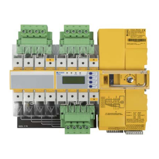
System description ATICS-4-DIO front view 13 12 Legend Green plug connector for line 1 Green plug connector for line 2 Control buttons Inspection window for switch position Manual mode of the device, indicates the switch position Allen key for manual mode Transparent cover for changeover switch (manual mode), sealable Wiring diagram for lines 1, 2 and 3 Three coded connector plugs... -
Page 27: Mounting And Connection
ATICS-…-DIO Mounting and connection of electrocution due to electric shock! Touching live parts of the system carries the risk of electric shock. Before installing and connecting the device, make sure that the installation has been de-energised. Observe the rules for working on electrical installations. - Page 28 Mounting and connection 104 *** 176 *** 14,7 115,3 326 ** Abb. 4–2 ATICS-2-DIO Additional space required for auxiliary contact when using the bypass switch Adapt the cutout to the terminal cover Dimensions for screw mounting on plate **** Additional space required for the connector plug of the measuring current transformer ***** 80 A/125 A version.
-
Page 29: Removing Terminal Cover
ATICS-…-DIO 4.1.2 Removing terminal cover 1. Push back the locking hook (B) in the middle of the top and bottom terminal cover (A) by N N N using a screwdriver. 2. Remove the terminal cover. 4.1.3 DIN rail mounting Description applies to ATICS-…-DIO ! Screws must be tightened, otherwise the vibrations generated during switching may aution damage the ATICS®. -
Page 30: Screw Mounting On Plate
Mounting and connection 4.1.4 Screw mounting on plate Description applies to ATICS-…-DIO • Observe dimension diagram of rear view. • Use M5 mounting screws : Screw heads or washers reduce voltage clearances. Provide for sufficient clearance to live aution conductors (voltage clearance) by using mounting screws with flat screw heads and flat washers. If mounted on electrically conductive material: The mounting plate has to be earthed and the area un- der the terminals has to be covered with insulating material. -
Page 31: Connecting The Atics® Safely
ATICS-…-DIO 4.2.2 Connecting the ATICS® safely of electrocution due to electric shock! If any of the supplies are switched on, some of the system parts which are not yet fully installed may be live. Preventing unintended switch-on: • Open the transparent cover •... - Page 32 Mounting and connection ATICS-2-DIO terminals IN2-4 IN1/ Legend Terminal Description 1, 3 Connection line 1 (input line) L, N 5, 7 Connection line 2 (input line) L, N 4, 6 Connection line 3 (output line) N, L l, k (grey) Connection measuring current transformer STW3/STW 4 (T3) for monitoring the load current downstream the transfer switching device (short-circuit monitoring) GND, En/Ex...
- Page 33 ATICS-…-DIO ATICS-4-DIO terminals IN2-4 IN1/ Legend Terminal Description 1, 3, 5, 7 Connection line 1 (input line) 1L1, 1L2, 1L3, 1N 9, 11, 13, 15 Connection line 2 (input line) 2L1, 2L2, 2L3, 2N 10, 12, 14, 16 Connection line 3 (output line) L1, L2, L3, N NC, NC (grey) Not used GND, En/Ex...
-
Page 34: Connection Examples Atics® Basic Configuration
4.2.3 Connection examples ATICS® basic configuration ! Risk of destruction if connected incorrectly. arning The terminals marked with "*" are intended for Bender-internal purposes only. If this is ignored, the ATICS® automatic transfer switching device may be damaged. ATICS-2-DIO ATICS-DIO_D00080_03_M_XXEN / 04.2021... - Page 35 ATICS-…-DIO ATICS-4-DIO ATICS-DIO_D00080_03_M_XXEN / 04.2021...
-
Page 36: Connection Examples: Atics® With Bypass Switch
4.2.4 Connection examples: ATICS® with bypass switch ! Risk of destruction if connected incorrectly. arning The terminals marked with "*" are intended for Bender-internal purposes only. If this is ignored, the ATICS® automatic transfer switching device may be damaged. ATICS-2-DIO... - Page 37 ATICS-…-DIO ATICS-DIO_D00080_03_M_XXEN / 04.2021...
- Page 38 Mounting and connection ATICS-4-DIO ATICS-DIO_D00080_03_M_XXEN / 04.2021...
- Page 39 ATICS-…-DIO ATICS-DIO_D00080_03_M_XXEN / 04.2021...
-
Page 40: Instructions For Connection
Ex works, terminals A and B are available for connecting BMS-enabled devices. Alarm indicator and test combinations, alarm indicator and operator panels or other bus-enabled Bender devices can be con- nected. The bus line must be terminated at both ends with resistors (120 Ω, 0.25 W). Please note the in- formation in the "BMS bus"... -
Page 41: Fastening, Inserting And Securing Connections
ATICS-…-DIO 4.2.6 Fastening, inserting and securing connections Connect the terminals to the plug connectors (A, B) and the three connector plugs (C) according to the wiring diagram. • Connect lines 1, 2 and 3 to the plug connectors (A,B). Observe the stripping length of 20 mm and do not use ferrules. -
Page 42: Other Functions
Mounting and connection Other functions 4.3.1 Sealing the transparent cover The transparent cover can only be sealed when it is closed (automatic mode). 4.3.2 Manual mode of injury from rotating Allen key. When the transparent cover is closed, the ATICS® is in automatic mode. The ATICS® detects this by the button being pressed under the transparent cover. -
Page 43: Commissioning, Settings And Testing
ATICS-…-DIO Commissioning, settings and testing Design and Installation of missing or incorrect displays on MK…, TM…, FTC… or CP9xx! MK… alarm indicator and test combinations, TM… alarm indicator and operator panels or COM460… BMS-Ethernet gateways which, together with an ATICS®, are connected to a BMS bus must be provided with the latest operating software (e.g. -
Page 44: Atics® Messages On The Bms Bus (Channel Use)
Commissioning, settings and testing This is achieved by entering the ATICS® device address in the alarm address table. If necessary, individu- al messages can also be programmed for channels 1, 2, 5, 7…11. No individual text may be pro- grammed for channel 6! The failure of the other MK…... - Page 45 ATICS-…-DIO Entry in the menu Description Operating Alarm mes- Error chan- 1. Alarm/meas.values message sage 10. Dig. input Dig. input3 --** Alarm text** 11. Dig. input Dig. input4 --** Alarm text** No function * Message dependent on the parameter assignment in the „Settings menu 1: Changeover“ on p. 67 -> "System" ** Message dependent on the input parameter assignment (see "„Messages for alarm on the digital input“...
- Page 46 Commissioning, settings and testing Entry in the menu Description Operating Alarm mes- Error chan- 1. Alarm/meas.values message sage 9. I(3):35A Load current in Current Current Connection fault the TN system on current trans- phase L3 former 10. I(3):35A Load current in Current Current Connection fault...
-
Page 47: Tests, Decommissioning
ATICS-…-DIO Menu Function of digital input Alarm on BMS bus BMS chan- settings 1<->2 Change preferred line No alarm TEST TEST- carry out changeover No alarm ALARM ATICS-2-DIO: Alarm "Digital input" 8, 9, 10, 11 Convert message at digital inputs 1…4 into alarms on the BMS bus. -
Page 48: Addressing Examples
Commissioning, settings and testing • As part of the response delay (to be custom-set), you must, at the very least, take into account the periods of time when the circuit experiences short interruptions, and the response times of the short-circuit protection equipment upstream or downstream. Regardless of this, a switchover pause corresponding to the installation location should be taken into account, in order to avoid switching overvoltages. -
Page 49: Operation
ATICS-…-DIO Operation Operating and display elements ALARM LED/Button Description LED "1" lights up: Line 1 is ready LED "2" lights up: Line 2 is ready LED "ALARM" lights up: Alarm present LED "COM" flashes: Communication via BMS bus "INFO" Query standard information "ESC"... -
Page 50: Quick Reference Guide
Operation Quick reference guide 6.2.1 Display under normal operating conditions Pos. Description ATICS-2-DIO Line 1: Measured values of mains voltage and frequency 228 V 231 V Switch position of the 50 . 0Hz 50 . 0Hz automatic transfer switching 12 : 23 160kΩ... -
Page 51: Test Function
228 V 0 . 00 V ATICS-…-DIO 50 . 0Hz 12 : 23 Press " " button to display the current alarm: Undervoltage • Line 1: ALARM xx / yy ALARM – xx = serial number of the displayed alarm Undervoltage –... - Page 52 Operation Test menus 2…4 are protected by a password (see chapter „Settings menu 10: Password“ on p. 80). Password protection is only effective if the password has been enabled. When an attempt is made to open one of these menus, the password entry screen appears automatically: TEST Enter password: 0 0 0...
-
Page 53: Test Menu 1: Autom. Changeover
ATICS-…-DIO 6.2.3.1 Test menu 1: Autom. changeover Autom. changeover Autom. changeover Cancel Autom. changeover Test of the changeover function. The device switches to the redundant line. The changeover period t(1->2) is displayed. After the set time t(test) has elapsed, the device switches back to the preferred line. Cancel Return to test menu Test... -
Page 54: Test Menu 3: Last Changeover
Operation Manual mode aborts manual test. When the transparent cover is opened after switching over to the redundant line, the ATICS® swit- ches to manual mode. The test will be aborted. After closing the transparent cover, the ATICS® swit- ches back to the preferred line. No entry will be made in the test logger. 6.2.3.3 Test menu 3: Last changeover If the ATICS®... -
Page 55: Test Menu 4: Generator
ATICS-…-DIO 6.2.3.4 Test menu 4: Generator Executing this function makes sense only when a generator is connected to the redundant line and the corresponding settings have been carried out (see chapter „Settings menu 1: Changeover“ on p. 67). To avoid voltage interruptions, in the test menu "Generator", the ATICS® does not switch to the redun- dant line. -
Page 56: Reset Function
Operation Select a channel: 1. Use the " " arrow button to go to the channel settings. Press the " " button. 2. Use the arrow buttons to select the channel for which the alarm message is to be simulated. Press the "... -
Page 57: Reset Menu 1: Alarm
ATICS-…-DIO 6.2.4.1 Reset menu 1: Alarm Delete Delete Cancel Delete Reset alarm and fault messages on the device. The progress of the test is shown on the display. The RESET is required if one or more alarm-triggering parameters are not constantly monitored and thus the end of the alarm condition has not been detected. -
Page 58: Reset Menu 4: Service Alarm
Operation Regardless of the IEC 61508-2 standard, the safe function of the device is of course still guaranteed due to the cyclical self-monitoring functions. Operation in accordance with DIN VDE 0100-710, DIN VDE 0100-718 or IEC 60364-7-710 is still possi- ble if the prescribed measures are implemented (see chapter „Periodic verification and service“... -
Page 59: Menu Mode: Operation And Setting
ATICS-…-DIO Menu mode: Operation and setting Switching on and calling up the main menu When the device is connected to the power supply, the follow- ing information appears on the display for approx. 3 seconds: If the device has been without power for several days, time and date must be readjusted. If there are no messages pending, the standard display will appear after the start. -
Page 60: Menu Overview Diagram
Menu mode: Operation and setting Menu overview diagram The following diagram will help you to navigate through the menus: Exit Exit 1.History 1.Alarm/meas.values 2.Data logger 3.Config. logger 2.Changeover 4.Test data logger 3.History/Logger 5.Service logger Exit 1.Changeover 2.Voltage 3.Current 4.Relay 5.Digital Input 4.Settings 6.Data logger 7.Language... -
Page 61: Function Of The Main Menu
ATICS-…-DIO Function of the main menu Menu item Function Page Exit Exit menu mode 1. Alarm/meas.values Display saved status messages, alarm messages and measured values P. 61 2. Changeover Display information on the changeover function (number, test) P. 64 3. History/Loggers Display history memory, data logger, configuration logger, test logger and P. -
Page 62: Alarm/Meas.values Atics-4-Dio
Menu mode: Operation and setting Menu Description No function Line 1: Measured value frequency Line 1: 50.0Hz Line 2: Measured value frequency Line 2: 50.0Hz 7.3.1.2 Alarm/meas.values ATICS-4-DIO Menu Description Exit Exit "Alarm/meas. values" menu; go up one menu level Line 1: Measured values mains voltage phase 1 to N* U1(1-N): 230V Line 2: Measured values mains voltage phase 1 to N*... - Page 63 ATICS-…-DIO Menu Description Line 1: Phase sequence of the phases L1, L2, L3 Phase seq: left Line 2: Measured value mains voltage phase L1 to neutral conductor N U2(1-N): 230V Line 2: Measured value mains voltage phase L2 to neutral conductor N U2(2-N): 230V Line 2: Measured value mains voltage phase L3 to neutral conductor N U2(3-N): 230V...
-
Page 64: Menu 2: Changeover
Menu mode: Operation and setting 7.3.2 Menu 2: Changeover Display information on the changeover function (number, test). The device shows the alarm status for each menu item: = no alarm, = alarm. Menu Description Exit Exit "Changeover" menu; go up one menu level Number of changeovers performed Changeover: xxx Operating hours counter (h=hours, d=days, mo=months) -
Page 65: Operating Example: History
ATICS-…-DIO Menu item Function 3. Config.logger Shows the history of all parameter changes, their origin, modified settings and the date of the change (can only be displayed on the device): Local Change has been made in the "Settings" menu on the device. External Change has been made via an external device (e.g. -
Page 66: Operating Example: Config.logger
(in this case: [4/1]). Channel 1 means that the first digital input has been changed. Please contact the Bender service and provide the identification number if the modification led to an undesirable behaviour of the device. 7.3.4 Menu 4: Settings The settings menus are protected by a password (see chapter „Settings menu 10: Password“... -
Page 67: Settings Menu 1: Changeover
The device has two separate passwords for the "Settings" menu and the "TEST" P. 80 menu. Adjustable in each case: change password, enable/disable password 11. Service Only intended for settings by authorised Bender service personnel. P. 81 Call up information about the device status and make settings for specific operat- ing conditions. - Page 68 Menu mode: Operation and setting Menu item Function 5. System U1-U2 Voltage line 1 - Voltage line 2 Line G Line 1 - Generator L1-L2 Line 1 - Line 2 AV-SV Normal power supply source - Safety power supply source SV-AV Safety power supply source - Normal power supply source SV-UPS...
-
Page 69: Settings Menu 2: Voltage
ATICS-…-DIO Menu item Function 10. Serviceinterv. Service interval: Setting range: off, 6…48 months Resolution of setting: 6 months 11. Reminder Warning time for service interval (d=day): Setting range: off, 1…60 days Resolution of setting: 1 day 12. t (GenStart) Time delay for changeover to generator (measured from "Voltage line 2 = OK"): Setting range: 0 s…100 s (only active when System=Line G) Resolution of settings:... -
Page 70: Settings Menu 3: Current
Exit settings menu "Current"; go up one menu level 1. Mode Current monitoring enabled No current monitoring 2. Current trans- STW3 Bender measuring current transformer STW3 former STW4 Bender measuring current transformer STW4 3. CT monitoring. CT connection monitoring enabled CT connection monitoring disabled Note: External interference from loads can cause false tripping. -
Page 71: Settings Menu 4: Relay
Exit settings menu "Current"; go up one menu level 1. Mode Current monitoring enabled No current monitoring 2. Current trans- STW3 Bender measuring current transformer STW3 former STW4 Bender measuring current transformer STW4 3. CT monitoring. CT connection monitoring enabled CT connection monitoring disabled Note: External interference from loads can cause false tripping. - Page 72 Menu mode: Operation and setting If "GenSt" is set, the operating mode for alarm relay 1 will always be set to "N/C-T". The other settings on the "Relay 1" menu are disabled. The alarm message "Failure line 2" is suppressed. If the setting "Line G"...
- Page 73 ATICS-…-DIO Adjusting the settings: Menu Description Exit Exit settings menu "Relay"; go up one menu level 1. Function ALARM Relay switches if at least one of the following menus 3…9 is set to "on" and the corresponding alarm message appears. Active Relay switches if at least one of the following menus 3…9 is set to "on"...
-
Page 74: Settings Menu 5: Dig. Input
Menu mode: Operation and setting The reminders for the test (7. Test interval) or the service (8. Serviceinterv) are always triggered at 12:00 pm. If these messages appear at night, the time is set incorrectly on the device. 7.3.4.5 Settings menu 5: Dig. input In this menu, you can adjust settings for the mode of operation and function of the digital inputs. - Page 75 ATICS-…-DIO Adjusting the settings: Menu Description Exit Exit settings menu "Voltage"; go up one menu level : A parameter change can result in an immediate changeover. 1. Functions Digital input disabled Manual/Automatic. Manual mode means that automatic changeover can no longer take place. Bypass Alarm "Bypass operation"...
-
Page 76: Settings Menu 6: Data Loggers
Menu mode: Operation and setting The common alarm for the digital inputs 2…4 is signalled on channel 12 of the BMS bus. If one of these digital inputs is set to "ALARM" and activated, an alarm is output on channel 12. It cannot be recognised which digital input has tripped. - Page 77 ATICS-…-DIO Data logger Description 6. U2(3-N) Line 2: Measured value mains voltage phase L3 to neutral conductor N 7. Position: 1 Switch position of the transfer switching device 8. I(1) Load current downstream of the transfer switching device on phase L1 8.
-
Page 78: Settings Menu 7: Language
Menu mode: Operation and setting Menu Description 2. Overwrite Once the maximum number of measured values which can be saved has been reached, the current measured value overwrites the oldest entry. Once the maximum number of measured values which can be saved has been reached, no further measured values are saved. -
Page 79: Settings Menu 9: Clock
ATICS-…-DIO Menu Description 4. Failure monitoring Reports when no (more) communication with the BMS master is detected. It is not monitored whether a BMS master is present. This setting is required when ATICS® is used as a "Stand-alone" device without BMS master. ! When this setting is selected, the conditions for functional sa- anger fety (SIL2) are no longer met. -
Page 80: Settings Menu 10: Password
Menu mode: Operation and setting 7.3.4.10 Settings menu 10: Password The device has two separate passwords for the "Settings" menu and the "TEST" menu. Menu Description Exit Exit settings menu "Password"; go up one menu level 1. Settings Change the password for the "Settings" menu, switch the password "on/off". Factory setting: Password: Status:... -
Page 81: Settings Menu 11: Service
The service menu is intended for settings by authorised Bender service personnel. It is only accessible to the Bender service. In the service menu, information about the device status can be called up and settings for specific operating conditions can be made. -
Page 82: Menu 7: Info
Address set on the BMS bus Address: 3 No.: 1234567890 Line 4: Serial number of the device Line 5…6: Software versions of the four controllers of the device … Bender address, website … Exit. Exit standard information. ATICS-DIO_D00080_03_M_XXEN / 04.2021... -
Page 83: Troubleshooting
If the device is operated without a BMS bus, the "Failure monitoring" (see chapter „Settings menu 8: Inter- face“ on p. 78) must be disabled. Service by __ Reminder for next service • Schedule appointment with the Bender service. (date) ATICS-DIO_D00080_03_M_XXEN / 04.2021... -
Page 84: Messages With Error Code Or Service Code
8.1.2 Messages with error code or service code Error code/service Description Action code 1.xx, 4.xx, 9.xx Fault message from the internal memory • Contact the Bender service. monitoring. 3.10 Prewarning • For functional safety SIL 2 require- ments according to IEC 61508-2, The max. number of the replacement must be planned. - Page 85 2. Note down what happened before the error: Operating steps, error messages of the device, environmental conditions, etc. 3. Have the article and serial number of the device at hand. 4. Contact the Bender service and state the type of error and the three-digit error code. ATICS-DIO_D00080_03_M_XXEN / 04.2021...
-
Page 86: Frequently Asked Questions
Troubleshooting Frequently asked questions A series of clicks is always heard at around noon. What does that mean? ATICS® carries out a coil trigger test once a day. The time is calculated as follows: 12:00:00 o'clock + (own BMS bus address * 10 s). If set to "Generator"... - Page 87 Why does writing back reports/backups lead to error messages? ATICS® – like many Bender devices – can be monitored and configured by means of a Bender gateway CP700, COM46x… etc. The gateways are operated via a web user interface that is displayed using an Internet browser.
- Page 88 Periodic verification and service ATICS-DIO_D00080_03_M_XXEN / 04.2021...
-
Page 89: Periodic Verification And Service
Periodic verification and service Periodic verification The use of Bender products ensures protective measures against certain hazards when operating elec- trical systems. The corresponding legal requirements are defined in the Ordinance on Industrial Safety and Health (BetrSichV) and the supplementary Technical Rules (TRBS): Every company is obliged to draw up a risk assessment for its work equipment (electrical systems and equipment). -
Page 90: Maintenance
Periodic verification and service Action To be Interval performed by Services for the periodic verification of Bender products in electrical Bender service Every twelve installations: or electrically months* • For checking the effectiveness of the protective measures monitored by skilled person Bender products as well as their disconnecting and switching functions, see „Settings menu 1: Changeover“... -
Page 91: Replacing The Atics
ATICS-…-DIO of short circuit if "Enable bypass" light is ignored. If ATICS® is not connected to the line to which the bypass switch is connected, a short circuit may oc- cur between line 1 and line 2. The bypass switch may only be operated when the green "Enable Bypass"... -
Page 92: Removing The Existing Atics
Periodic verification and service 9.5.1 Removing the existing ATICS® Description applies to ATICS-…-DIO. 1. Record settings on the existing ATICS®. The settings should match the entries in the checklist (see checklist, included in the scope of delivery). 2. Disconnect the device from the power supply or switch on the bypass switch. Switch existing ATICS®... - Page 93 ATICS-…-DIO Removing the ATICS® in case of DIN rail mounting Undo screws (D). N N N Remove lower and upper terminal covers (A) by using a screw- driver to push back the locking hook (B) located approximately in the middle of the cover in each case. ATICS-2-DIO: Use a screwdriver to pull the lower yellow slide lock (C) downwards and raise the ATICS®...
-
Page 94: Installing A New Atics
Periodic verification and service Removing the ATICS® in case of screw mounting Remove lower and upper terminal covers (A) by using a N N N screwdriver to push back the locking hook (B) located ap- proximately in the middle of the cover in each case. Undo the Allen screws of the terminals (C). -
Page 95: Technical Data
ATICS-…-DIO Technical data 10.1 Tabular data Insulation coordination acc. to IEC 60664-1/IEC 60664-3 Overvoltage category ��������������������������������������������������������������������������������������������������������������������������������������������������������������������������������� III Pollution degree outside, inside ������������������������������������������������������������������������������������������������������������������������������������������������������������������ 2 Rated insulation voltage ATICS-2-DIO/ATICS-4-DIO ��������������������������������������������������������������������������������������������������������������������250 V/400 V Protective separation between ������������������������������������������������������������������������������������������������������������Line 1 – Line 2; Line 1, 2, 3 – RS-485 ��������������������������������������������������������������������������������������������������������������������������������... - Page 96 Technical data Cable length: Single wire ≥ 0�75 mm² ������������� ��������������������������� ���������������������������������������������������������������������������������������������������������������������������0…1 m Single wire, twisted ≥ 0�75 mm² ������ ��������������������������� ������������������������������������������������������������������������������������������������������������������1…10 m Shielded cable ������������������������������������ �������������������������� ����������������������������������������������������������������������������������������������������������������10…40 m Cable: twisted pairs, shield connected to terminal I on one side, must not be earthed������������������ recommended: J-Y(St)Y min� n x 2 x 0�8 Displays and data memory Display: graphic display��...
- Page 97 ATICS-…-DIO BMS interface Interface/protocol� ����������������������������������������������������������������������������������������������������������������������������������������������������������������������RS-485/BMS Baud rate������������ ����������������������� �����������������������������������������������������������������������������������������������������������������������������������������������������9�6 kBit/s Cable length����������������������������������������������������������������������������������������������������������������������������������������������������������������������������������� ≤ 1200 m Cable: shielded, one end of shield connected to PE ���������������������������������������������������������������������������������������������� CAT6/CAT7 min� AWG23* * alternatively: ��������������������������������������������������������������������������������������twisted pair, one end of shield connected to PE J-Y(St)Y min� 2x0�8 Terminating resistor �...
- Page 98 Technical data Other Operating mode �� �������������������������������������������������������������������������������������������������������������������������������������������������������� continuous operation Mounting ����� �������������������������� ���������������������������������������������������������������������������������������������������������������������������������������������display-oriented For use at altitudes����� ����������������� �����������������������������������������������������������������������������������������������������������������������������������up to 2000 m AMSL Protection class ������������ ������������������������������������������������������������������������������������������������������������������������������������������������������������������������Class I Protection class LCD under foil (DIN EN 60529)���� ������������������� ��������������������������������������������������������������������������������������������������������������� IP40 Enclosure material ������ ����������������������������������������������������������������������������������������������������������������������������������������������������������� polycarbonate Flammability class����...
-
Page 99: Tüv Test Report According To Vde 0100 Part 710
ATICS-…-DIO 10.2 TÜV test report according to VDE 0100 Part 710 ATICS-DIO_D00080_03_M_XXEN / 04.2021... -
Page 100: Tüv Certificate Regarding Functional Safety
Technical data 10.3 TÜV certificate regarding functional safety ATICS-DIO_D00080_03_M_XXEN / 04.2021... -
Page 101: Standards And Certifications
ATICS-…-DIO 10.4 Standards and certifications The transfer switching device conforms to the following standards: • DIN VDE 0100-710 (VDE 0100 Part 710):2002-11* • DIN VDE 0100-710 (VDE 0100 Part 710):2012-10* • DIN VDE 0100-710 (VDE 0100-710) supplement 1:2014-06 • DIN VDE 0100-718 (VDE 0100-718):2014-06 •... - Page 102 Technical data 4-pole transfer switching device, 4 dig� in- puts, 4 relay outputs, short-circuit detection in TN systems, with sealable contact covers on the input and output sides, bridges on the ATICS-4-160A-DIO AC 160 A B92057224 D00080 output side, screw-type terminals (not plug- gable) for lines I, II, III�...
-
Page 103: Additional Documents
• ATICS-BP-SET (bypass switch set for ATICS®) • STW2, STW3, STW4 measuring current transformers • BMS bus Bender measuring device interface • COM465… BMS-Ethernet gateway for the connection of the Bender measuring device inter- face to TCP/IP networks • MK2430 alarm indicator and test combination •... - Page 104 Nachdruck und Vervielfältigung Reprinting and duplicating nur mit Genehmigung des Herausgebers. only with permission of the publisher. Bender GmbH & Co. KG Bender GmbH & Co. KG Postfach 1161 • 35301 Grünberg • Deutschland PO Box 1161 • 35301 Grünberg • Germany Londorfer Str.