Bender ATICS-2-63A-DIO Manual
Automatic transfer switching devices for safety power supplies
Hide thumbs
Also See for ATICS-2-63A-DIO:
- Manual (104 pages) ,
- Quick start manual (12 pages) ,
- Manual (90 pages)
Table of Contents

Related Manuals for Bender ATICS-2-63A-DIO


Summary of Contents for Bender ATICS-2-63A-DIO
- Page 1 Manual ATICS-2-63A-DIO, ATICS-2-80A-DIO, ATICS-4-80A-DIO, ATICS-4-125A-DIO, ATICS-4-160A-DIO Automatic transfer switching devices for safety power supplies Software version: D333 V1.2x/D334 V1.2x/D335 V1.0x ATICS-DIO_D00080_02_M_XXEN/08.2017...
- Page 2 Bender GmbH & Co. KG © Bender GmbH & Co. KG All rights reserved. P.O. Box 1161 • 35301 Gruenberg • Germany Londorfer Straße 65 • 35305 Gruenberg • Germany Reprinting only with permission Tel.: +49 6401 807-0 • Fax: +49 6401 807-259 of the publisher.
-
Page 3: Table Of Contents
Table of Contents 1. Important information ................... 7 How to use this manual ......................7 Technical support: service and support ................8 1.2.1 First level support ........................8 1.2.2 Repair service ..........................8 1.2.3 Field service ..........................8 Training courses ........................9 Delivery conditions ......................... - Page 4 Table of Contents 3.5.1.3 Time diagram: Changeover to generator mode ..........20 3.5.2 Monitoring the device functions ..................21 3.5.3 Power supply ........................... 21 3.5.4 Manual mode .......................... 21 ATICS-2-DIO front view ....................... 22 ATICS-4-DIO front view ....................... 23 4. Installation and connection ................25 Mounting ..........................
- Page 5 Table of Contents Addressing example ......................46 6. Operation ....................... 47 Operating and display elements ..................47 Quick reference guide ......................48 6.2.1 ATICS-2-DIO: Display under normal operating conditions ........48 6.2.2 ATICS-4-DIO: Display under normal operating conditions ........49 6.2.3 Display during fault condition ..................
- Page 6 Table of Contents 7.3.4.10 Settings menu 10: Password ..................81 7.3.4.11 Settings menu 11: Service ................... 82 7.3.5 Menu 5: Control ........................83 7.3.6 Menu 6: Digital Input ......................83 7.3.7 Menu 7: Info ..........................83 8. Troubleshooting ....................85 Fault and alarm messages ....................
-
Page 7: Important Information
This manual describes how to operate the ATICS® automatic transfer switching device. Before using the devices, please read this operating manual, the supplement entitled "Important safety instructions for Bender products" and the instruction leaflets supplied with the individual sys- tem components. -
Page 8: Technical Support: Service And Support
Important information This manual has been compiled with great care. It might nevertheless contain errors and mistakes. Bender cannot accept any liability for injury to persons or damage to property resulting from errors or mistakes in this manual. ATICS® is a registered trademark of Bender GmbH & Co. KG. -
Page 9: Training Courses
**Mo-Thu 7.00 a.m. - 8.00 p.m., Fr 7.00 a.m. - 13.00 p.m. 1.3 Training courses Bender is happy to provide training regarding the use of test equipment. The dates of training cours- es and workshops can be found on the Internet at www.bender-de.com -> Know-how -> Seminars. -
Page 10: Disposal
introduced to the market after 13 August 2005 must be taken back by the manufacturer and disposed of properly. For more information on the disposal of Bender devices, refer to our website at www.bender-de.com -> Service & support. ATICS-DIO_D00080_02_M_XXEN/08.2017... -
Page 11: Safety Instructions
2.1 General safety instructions Part of the device documentation in addition to this manual is the enclosed "Safety instructions for Bender products". 2.2 Work activities on electrical installations Only qualified personnel are permitted to carry out the work necessary to in- stall, commission and run a device or system. -
Page 12: Device-Specific Safety Instructions
2.5 General safety instructions Bender devices are designed and built in accordance with the state of the art and accepted rules in respect of technical safety. However, the use of such devices may introduce risks to the life and limb of the user or third parties and/or result in damage to Bender devices or other property. -
Page 13: System Description
3. System description 3.1 Properties 3.1.1 Product description The ATICS® transfer switching devices provide all functions for changeover between two independ- ent power supplies. The integration of both the electronic system and the switching elements in one flat, compact device reduces space requirements in the switchgear cabinet, minimises the amount of wiring, and reduces the fault probability. -
Page 14: Functional Safety
Responsibility during the life cycle: Production Commissioning Maintenance Decommissioning Recycling Bender plant operator Bender For detailed information refer to chapter "5. Commissioning, settings and testing" on page 41 chapter "9. Periodic verification and service" on page 91 ... -
Page 15: Application Example
System description 3.3 Application example ATICS-2-63A-DIO: Changeover between the preferred and the redundant line MK2430/MK800/TM800: Alarm at at least two points with independent power supplies for func- tional safety RCMS: RCMS460 or RCMS490 residual current monitors for localising residual and operating ... -
Page 16: Atics® Tasks
System description 3.4 ATICS® tasks The ATICS® transfer switching device has the following capabilities: Two-pole or four-pole changeover of the power supply Voltage monitoring for the preferred supply (Line 1) Voltage monitoring for the second supply (Line 2) ... - Page 17 If ATICS® detects a supply failure or a fault, an alarm appears on the LCD, the "ALARM" LED lights up, the alarm relay trips (if set) and this alarm is forwarded to other Bender devices (such as an alarm in- dicator and test combination) via the BMS bus.
-
Page 18: Time Diagram: Changeover Between The Preferred And The Redundant Line
System description 3.5.1.1 Time diagram: Changeover between the preferred and the redundant line Example: Line 1 is set as the preferred line. ATICS-DIO_D00080_02_M_XXEN/08.2017... -
Page 19: Time Diagram: Staggered Switching After Complete Power Failure
System description 3.5.1.2 Time diagram: Staggered switching after complete power failure After a complete power failure (i.e. no voltage on either of the power supplies) it is often necessary to switch to the supply at staggered intervals. This prevents all loads being switched on simultane- ously. -
Page 20: Time Diagram: Changeover To Generator Mode
System description 3.5.1.3 Time diagram: Changeover to generator mode ATICS-DIO_D00080_02_M_XXEN/08.2017... -
Page 21: Monitoring The Device Functions
System description 3.5.2 Monitoring the device functions The control circuits are designed in such a way that, even though it is almost certain that a particular fault will occur, it cannot cause the power supply at the output of the automatic transfer switching device to fail. -
Page 22: Atics-2-Dio Front View
System description 3.6 ATICS-2-DIO front view Legend Green plug connector for line 1 and line 2 Control buttons Inspection window for switch position Manual mode of the transfer switching device, indicates the switch position Allen key for manual mode Transparent cover for changeover switch (manual mode), sealable Wiring diagram for lines 1, 2 and 3 Three coded connector plugs Locking device for switch position 0... -
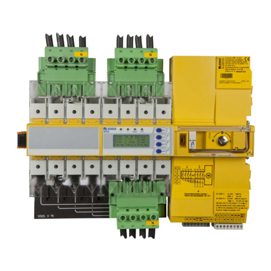
Page 23: Atics-4-Dio Front View
System description 3.7 ATICS-4-DIO front view 13 12 Legend Green plug connector for line 1 Green plug connector for line 2 Control buttons Inspection window for switch position Manual mode of the transfer switching device, indicates the switch position Allen key for manual mode Transparent cover for changeover switch (manual mode), sealable Wiring diagram for lines 1, 2 and 3 Three coded connector plugs... - Page 24 System description ATICS-DIO_D00080_02_M_XXEN/08.2017...
-
Page 25: Installation And Connection
4. Installation and connection Risk of electrocution due to electric shock! Touching live parts of the system carries the risk of electric shock. Before fitting the device and prior to working on the device connections, make sure that the DANGER power supply has been disconnected. -
Page 26: Atics-2-Dio Dimension Diagram
Installation and connection 4.1.1 ATICS-2-DIO dimension diagram 14,7 115,3 73,5 Only when using the bypass switch ATICS-BP-…: additional space required for auxiliary contact ** Adjust the cutout to the terminal cover *** Dimensions for screw mounting on mounting plate 4.1.2 ATICS-4-DIO dimension diagram 14,7 115,3... -
Page 27: Removing The Terminal Covers
Installation and connection 4.1.3 Removing the terminal covers 1. Push back the locking hook (B) in the middle of the top and bottom terminal cover (A) using a screwdriver. 2. Remove the terminal cover. 4.1.4 Mounting on DIN rail 1. Place ATICS® on the top edge of the rail. 2. -
Page 28: Screw Mounting On Plate
Installation and connection 5. Always tighten the mounting screws (D) (PZ1, 8,8 lb-in, 1 Nm). If the screws are not tight- ened, the vibration occur- ring during the switching CAUTION process damage ATICS®. 4.1.5 Screw mounting on plate Provide for sufficient clearance to live conductors (voltage clearance) by using mounting screws with flat screw heads and flat washers. -
Page 29: Connection
Installation and connection 4.2 Connection 4.2.1 Short-circuit protection The choice of back-up fuses F should ensure both short-circuit protection for the transformer and se- lectivity for the overcurrent devices connected downstream in the IT systems. The connecting wires between the automatic transfer switching devices and the overcurrent protec- tive device downstream are to be laid so that they are short-circuit and earth-fault proof. -
Page 30: Connecting Atics® Safely
Installation and connection 4.2.2 Connecting ATICS® safely Risk of fatal injury from electric shock If any of the supplies are switched on, some of the parts of the system which are not yet fully installed may be live. DANGER Open the transparent cover of the device for manual mode selection and wait until the display shows "Manual mode". - Page 31 Connection measuring current transformer T3 (STW3) for monitoring the load current downstream of the transfer switching device (short-circuit monitoring) GND, En/Ex Connection must not be used. Intended for Bender-internal purposes only (12 IN1/GND, IN1 Digital input, configurable (see "Settings menu 5: Digital input" on page 75)
- Page 32 L1, L2, L3, N Connection line 3 (output line) Not used GND, En/Ex Connection must not be used. Intended for Bender-internal purposes only (12 IN1/GND, IN1 Digital input, configurable (see "Settings menu 5: Digital input" on page 75) 24, 34, 44, 21...
-
Page 33: Connection Example: Atics-2-Dio Basic Configuration
Installation and connection 4.2.3 Connection example: ATICS-2-DIO basic configuration Risk of destruction if connected incorrectly The terminals marked "*" are intended for Bender-internal purposes only. If this is ignored, the ATICS® transfer switching device may be damaged. CAUTION ATICS-DIO_D00080_02_M_XXEN/08.2017... -
Page 34: Connection Example: Atics-4-Dio Basic Configuration
Installation and connection 4.2.4 Connection example: ATICS-4-DIO basic configuration Risk of destruction if connected incorrectly The terminals marked "*" are intended for Bender-internal purposes only. If this is ignored, the ATICS® transfer switching device may be damaged. CAUTION ATICS-DIO_D00080_02_M_XXEN/08.2017... -
Page 35: Connection Example: Atics-2-Dio With Bypass Switch
Installation and connection 4.2.5 Connection example: ATICS-2-DIO with bypass switch Risk of destruction if connected incorrectly The terminals marked "*" are intended for Bender-internal purposes only. If this is ignored, the ATICS® transfer switching device may be damaged. CAUTION ATICS-DIO_D00080_02_M_XXEN/08.2017... -
Page 36: Connection Example: Atics-2-Dio With Bypass Switch
Installation and connection 4.2.6 Connection example: ATICS-2-DIO with bypass switch Risk of destruction if connected incorrectly The terminals marked "*" are intended for Bender-internal purposes only. If this is ignored, the ATICS® transfer switching device may be damaged. CAUTION ATICS-DIO_D00080_02_M_XXEN/08.2017... -
Page 37: Instructions For Connection
Ex works, the terminals A and B are available for connecting BMS-enabled devices. Alarm indicator and test combinations, alarm indicator and operator panels or other bus-enabled Bender devices can be connected. The bus line must be terminated at both ends with resistors (120 Ω, 0.25 W). -
Page 38: Fastening, Inserting And Securing Connections
Installation and connection 4.2.8 Fastening, inserting and securing connections Connect the terminals to the plug connectors (A, B) and the connector plugs (C, D) according to the wiring diagram. Connect the lines 1, 2 and 3 to the plug connectors (A, B). Consider a stripping length of 20 mm ... -
Page 39: Other Functions
Installation and connection 4.3 Other functions 4.3.1 Sealing the transparent cover of the transfer switching device The transparent cover can only be sealed when it is closed (automatic mode). 4.3.2 Manual mode Risk of injury from rotating Allen key When the transparent cover is closed, ATICS® is in automatic mode. ATICS® de- tects this by means of the button being pressed under the transparent cover. -
Page 40: Locking The Transfer Switching Device With A Padlock
Installation and connection 4.3.3 Locking the transfer switching device with a padlock It is only possible to lock the selector switch in manual mode (transparent cover open). The locking device can only be locked in switch position "0". Padlock shackle diameter: 4 mm … 8 mm (3/16” … 5/16”) Locking the transfer switching device: 1. -
Page 41: Commissioning, Settings And Testing
5. Commissioning, settings and testing 5.1 Design and installation Risk of missing or false messages on the display on MK..., TM... or FTC... MK… alarm indicator and test combinations, TM... alarm indicator and opera- tor panels or BMS Ethernet gateways COM465…, which, together with ATICS®, CAUTION are connected to a BMS bus must be loaded with the latest operating software (e.g. -
Page 42: Configure Mk
Commissioning, settings and testing 5.1.1 Configure MK… or TM… Configure MK… or TM… in a meaningful way In addition to the alarm, also configure a brief message of what to do or who to notify. Examples: - Failure line 1. Call building services Tel. -123. MK…... -
Page 43: Atics-4-Dio: Messages On The Bms Bus (Channel Use)
Commissioning, settings and testing 5.1.3 ATICS-4-DIO: Messages on the BMS bus (channel use) Operation Entry in the menu Alarm chan 1.Alarm/meas. Description Error status message values message 1. Line 1: 228V Line 1 Voltage Voltage* Phase sequence left, unbalance 2. Line 2: 183V Line 2 Voltage Voltage*... -
Page 44: Tests, Decommissioning
Commissioning, settings and testing Messages for alarm on the digital input The following operational status and alarm messages may appear depending on the settings in the "Settings menu 5: Digital input": Menu Function of digital input Alarm on BMS bus BMS channel setting Digital input switched off... -
Page 45: Setting And Testing According To The Checklist
Commissioning, settings and testing 5.2 Setting and testing according to the checklist The settings made at the factory take into account a total changeover period t ≤ 0.5 s and switching back to the preferred supply within 10 seconds on voltage recovery. The response delay t(on), the dead time t(0), the delay on release t(off) and the return transfer delay time t(2->1) of ATICS®... -
Page 46: Addressing Example
Commissioning, settings and testing 5.3 Addressing example Insert terminating resistors correctly Communication via the BMS bus is only guaranteed when there is a terminating resistor at the beginning and at the end of the BMS bus. Other terminating resis- tors cause malfunctions and must not be used. Please note the information in the "BMS bus"... -
Page 47: Operation
6. Operation This chapter can also be used as a quick reference guide by technical operating personnel. 6.1 Operating and display elements ALARM COM LED and LCD Illuminated graphic LCD LED "1" lights up when line 1 is ready LED "2" lights up when line 2 is ready LED "Alarm"... -
Page 48: Quick Reference Guide
Operation 6.2 Quick reference guide 6.2.1 ATICS-2-DIO: Display under normal operating conditions There is no alarm message. The LCD shows the standard information. Example: 228V 231V 50.0Hz 50.0Hz 14:11 12.10.2010 Legend Line 1: Measured values of mains voltage and frequency Switch position of the transfer switching device Date and time Line 2: Measured values of mains voltage and frequency... -
Page 49: Atics-4-Dio: Display Under Normal Operating Conditions
Operation 6.2.2 ATICS-4-DIO: Display under normal operating conditions There is no alarm message. The LCD shows the standard information. Example: 228V 230V 227V 229V 229V 231V 14:11 50.0Hz 50.0Hz 12.10.2010 Legend Line 1: Measured values of mains voltage and frequency Switch position of the transfer switching device Date and time Line 2: Measured values of mains voltage and frequency... -
Page 50: Display During Fault Condition
Operation 6.2.3 Display during fault condition There is an alarm message. The yellow "Alarm" LED lights up. A detailed message appears on the LC display. Example: Line 2 has no voltage 228V 0.00V ATICS-2-DIO 50.0Hz 0.00Hz 14:11 Undervoltage 228V 0.00V ATICS-4-DIO... -
Page 51: Test Function
Operation 6.2.4 Test function A test is used to test the functioning of the device. There are several ways to call up a test menu: Select standard display and then press the "TEST" button on the front panel of the device for at ... -
Page 52: Test Menu 1: Autom. Changeover
Operation If manual mode is selected for changeover (transparent cover open or digital in- put set to "manual changeover") then no changeover can take place under the test menu "Autom. changeover" or "Manual changeover". ATICS® then displays the following fault alarm: Info TEST Cancel... -
Page 53: Test Menu 2: Manual Changeover
Operation 6.2.4.2 Test menu 2: Manual changeover Manual changeover Manual changeover Cancel Manual changeover Test of the changeover function. The device changes to the redundant line and remains in this switch position. The changeover period t(1->2) is dis- played. The device does not change back to the preferred line until the "RE- SET"... -
Page 54: Test Menu 3: Last Switch
Operation 6.2.4.3 Test menu 3: Last switch If ATICS® has changed over due to a failure or a planned shutdown of the preferred line, then the last switching operation can be saved as a test. Last switch 1.Date: 20.09.11 2.TEST: 02.03.11 Save 1. -
Page 55: Test Menu 4: Generator
Operation 6.2.4.4 Test menu 4: Generator Executing this function makes sense only when a generator is connected to the redundant line and the associated settings have been carried out (see "Settings menu 1: Changeover" on page 69). To avoid voltage interruptions, in the test menu "Generator", ATICS®... -
Page 56: Test Menu 5: Test Communication
Operation 6.2.4.5 Test menu 5: Test communication Test communication via the BMS bus. In order to do this, a fault message is simulated. This alarm message is sent to evaluator devices (e.g. alarm indicator and operator panels, MK800, SMO…). Check that these devices are responding to the alarm message as requested. Select a channel: 1. -
Page 57: Reset Function
Operation 6.2.5 Reset function A RESET is used to reset the alarm and fault messages for the device and for reactivating the switch- ing back interlocking function of the changeover switch. There are several ways to call up a test menu: Select standard display and then press the "RESET"... -
Page 58: Reset Menu 2: Switchbacklock
Operation 6.2.5.2 Reset menu 2: SwitchBackLock Delete Delete Cancel Delete Cancels the switching back interlocking function for changeover. The progress of the test is shown on the display. The device changes back to the redundant line. Cancel Back to reset menu There are different possibilities to deactivate the switching back interlocking function via a gateway (COM4xx, CP700 etc.): Via menu: Select "RESET >... -
Page 59: Reset Menu 3: Changeover
Operation 6.2.5.3 Reset menu 3: Changeover ATICS® monitors the parameters important for its service life. On reaching the set limits, the unit dis- plays an alarm message. Replacement of the device must be initiated. During the period until it is re- placed the annoying alarm can be "deleted"... - Page 60 Operation ATICS-DIO_D00080_02_M_XXEN/08.2017...
-
Page 61: Menu Mode: Operation And Setting
7. Menu mode: Operation and setting 7.1 Switching on and calling up the main menu When the device is connected to the power supply, the following information appears on the display for approx. 3 seconds. If the device has been without power for several days, the time and date must be reset. -
Page 62: Menu Overview Diagram
Menu mode: Operation and setting 7.2 Menu overview diagram The following diagram will help you to navigate through the menus: Exit Exit 1.History 1.Alarm/meas.values 2.Data logger 3.Config. logger 2.Changeover 4.Test data logger 3.History/Logger 5.Service logger Exit 1.Changeover 2.Voltage 3.Current 4.Relay 5.Digital Input 4.Settings 6.Data logger... -
Page 63: Main Menu Functions
Menu mode: Operation and setting 7.3 Main menu functions Menu item Function Page Exit Exit menu mode 1. Alarm/meas.values Displays saved status messages, alarm messages and measured values 2. Changeover Displays information on the changeover function (number, test) 3. History/Logger Displays the history memory, data logger, config. -
Page 64: Alarm/Meas. Values Atics-4-Dio
Menu mode: Operation and setting Menu Meaning without function Line 1: Measured value frequency Line 1: 50.0Hz Line 2: Measured value frequency Line 2: 50.0Hz 7.3.1.2 Alarm/meas. values ATICS-4-DIO Menu Meaning Exit Exit "Alarm/meas. values" menu; go up one menu level Line 1: Measured values mains voltage phase 1 to N* U1(1-N): 230V Line 2: Measured values mains voltage phase 1 to N*... -
Page 65: Menu 2: Changeover
Menu mode: Operation and setting Menu Meaning Line 1: Phase sequence of the phases L1, L2, L3 Phase sequence: left Line 2: Measured value mains voltage phase L1 to neutral conductor N U2(1-N): 230V Line 2: Measured value mains voltage phase L2 to neutral conductor N U2(2-N): 230V Line 2: Measured value mains voltage phase L3 to neutral conductor N U2(3-N): 230V... -
Page 66: Menu 3: History/Logger
Menu mode: Operation and setting 7.3.3 Menu 3: History/Logger The device saves the history of alarm messages, measured values, settings, tests and servicing activ- ities in different memories (logger). See the technical specifications for information about the maximum number of events which can be saved. -
Page 67: Operating Example: History
"off" to "0". The last line contains an identification code for the type of modification (in this case: [4/1]). Channel 1 means that the first digital input has been changed. Please contact the Bender service and provide the identification number, when the modifica- tion led to an undesirable behaviour of the device. -
Page 68: Menu 4: Settings
"TEST" menu. Adjustable in each case: Change password, enable/disable password 11. Service These settings can only be made by authorised Bender service personnel. Retrieve information about the device status, enter settings for special oper- ating conditions and execute a firmware update. -
Page 69: Settings Menu 1: Changeover
Menu mode: Operation and setting 7.3.4.1 Settings menu 1: Changeover The times set in this menu determine the timing of a changeover. Also note the time charts on page 18 et seq. The following settings for the changeover are available: Menu Meaning Exit... - Page 70 Menu mode: Operation and setting Menu Meaning 6. SwitchBackLock Switching back interlocking function is switched on Switching back interlocking function is switched off Also refer to "Time diagram: Changeover between the preferred and the redun- dant line" on page 18. 7.
-
Page 71: Settings Menu 2: Voltage
Menu mode: Operation and setting 7.3.4.2 Settings menu 2: Voltage In this menu, you can adjust settings for monitoring the voltage on line 1 and line 2 individually or together. Example: Line 1 is set to "Undervolt: 184 V". If the voltage on line 1 falls below 184 V, the device displays an alarm message. -
Page 72: Settings Menu 3: Current
Exit settings menu "Current"; go up one menu level 1. Mode Current monitoring is switched on Current monitoring switched off 2. CT STW3 Bender measuring current transformer STW3 STW4 Bender measuring current transformer STW4 3. CT monitor CT connection monitoring is switched on CT connection monitoring switched off Note: External interference from loads can cause false tripping. -
Page 73: Settings Menu 4: Relay
Menu mode: Operation and setting 7.3.4.4 Settings menu 4: Relay In this menu, you adjust settings for the mode of operation and function of the relay outputs (alarm relays). The function can be set for each relay as follows: alarm message, operational status message. - Page 74 Menu mode: Operation and setting Adjusting the settings: Meaning Menu Exit Exit settings menu "Relays"; go up one menu level 1. Function ALARM Relay switches if at least one of the following menus 3…9 is set to "on" and the associated alarm message appears. Active Relay switches if at least one of the following menus 3…9 is set to "on"...
-
Page 75: Settings Menu 5: Digital Input
Menu mode: Operation and setting 7.3.4.5 Settings menu 5: Digital input In this menu, you can adjust settings for the mode of operation and function of the digital inputs. The digital inputs are galvanically isolated. They are designed for an input of AC/DC 24 V. For each input, selection is possible when the input is set to: "24V"... - Page 76 Menu mode: Operation and setting Menu Meaning 1. Function Note: A parameter change may cause an immediate changeover. Digital input switched off Manual/Automatic. Manual mode means that automatic changeover can no longer take place. Bypass Alarm "Manual mode", but TEST changeover possible no2->1 Switching back interlocking function.
-
Page 77: Settings Menu 6: Data Logger
Menu mode: Operation and setting Do not set inputs with contradictory functions simultaneously! For each of the four digital inputs a function can be set. This function is only acti- vated when the input is activated. Example: Digital input is set to "1" Digital input 2 is set to "2"... - Page 78 Menu mode: Operation and setting Data logger Meaning 10. I(3) Load current downstream of the transfer switching device on phase L3 11. I(N) Load current downstream of the transfer switching device on neutral con- ductor N Selecting a data logger: 1.
-
Page 79: Settings Menu 7: Language
Menu mode: Operation and setting Adjusting settings and deleting data loggers: Menu Meaning Exit Exit settings menu "Data logger"; go up one menu level 1. Modific. Once the measured value is changed according to the set % value, a new meas- ured value is saved to the data logger. -
Page 80: Settings Menu 9: Clock
Menu mode: Operation and setting Menu Meaning 4. Failure monitoring Indicates when communication with the BMS master has not been detected (anymore). The presence of a BMS master is not monitored. This setting is required when ATICS® is used as a "Stand-alone" device without BMS master. When this setting is selected, the conditions for functional safety (SIL2) are no longer met. -
Page 81: Settings Menu 10: Password
Menu mode: Operation and setting 7.3.4.10 Settings menu 10: Password The device has two separate passwords for the "Settings" menu and the "TEST" menu. Menu Meaning Exit Exit settings menu "Password"; go up one menu level 1. Settings Change the password for the "Settings" menu, switch the password "on/off". Fac- tory setting: Password: Status:... -
Page 82: Settings Menu 11: Service
Password protection is disabled. 7.3.4.11 Settings menu 11: Service Only Bender service personnel are authorised to make settings in the Service menu. It is only acces- sible to Bender service. In the Service menu, information about the device status can be called up and settings for specific operating conditions can be made. -
Page 83: Menu 5: Control
Line 2: Date, time Line 3: Address set on the BMS bus Line 4: Serial number of the device Line 5…6: Software versions of the two controllers of the device … Bender address, website … Exit. Exit standard information. ATICS-DIO_D00080_02_M_XXEN/08.2017... - Page 84 Menu mode: Operation and setting ATICS-DIO_D00080_02_M_XXEN/08.2017...
-
Page 85: Troubleshooting
8. Troubleshooting 8.1 Fault and alarm messages In the event of an alarm, the messages of ATICS® will enable you to narrow down the possible causes. Some messages may point to several causes. The following possible faults are indicated by messages on the ATICS®... -
Page 86: Messages With Error Code Or Service Code
Troubleshooting Fault/message Description Action Service: __ (date) Reminder for next service - Agree date with Bender service. Functional test: Reminder for next test - Plan date for test. __ (date) - Run test. Manual mode Message "Manual mode" although - Check the connections of the digital input. - Page 87 2. Make a note of what happened prior to the fault: operator inputs, device error messages, ambi- ent conditions, etc. 3. Keep the article and serial number of the device to hand. 4. Speak to Bender Service, describe the type of fault and quote the three-digit error code. ATICS-DIO_D00080_02_M_XXEN/08.2017...
-
Page 88: Frequently Asked Questions
Troubleshooting 8.2 Frequently asked questions A series of clicks is always heard at around noon. What does that mean? ATICS® carries out a coil trigger test once a day. The time is calculated as follows: 12:00:00 o'clock + (own BMS bus address * 10 s). If configured to "Generator"... - Page 89 Why does writing back reports/backups lead to error messages? ATICS® can – like many Bender devices – be monitored and configured by means of a Bender gate- way CP700, COM46x… etc. The gateways are operated via a web user interface which is represented by means of an Internet browser.
- Page 90 Troubleshooting ATICS-DIO_D00080_02_M_XXEN/08.2017...
-
Page 91: Periodic Verification And Service
Time interval according to DIN VDE 0100-710 (VDE 0100 Part 710):2002-11: 6 months. Thereby the minimum requirements are satisfied. Bender recommends a monthly test to ensure that the operating personnel is familiar with the test- ing procedure in the event of a fault. -
Page 92: Maintenance
Periodic verification and service 9.2 Maintenance The ATICS® system does not contain any parts that must be maintained. Despite this, the intervals specified for periodic verification should be adhered to. We also recommend regularly checking the Allen screws at the ATICS® and the Torx® screws of the connectors on the incoming and outgoing lines of the automatic transfer switching device to make sure they are tight. -
Page 93: Replace Atics
Periodic verification and service Conditions for operation with the bypass switch Wiring must be carried out according to "Connection example: ATICS-2-DIO with bypass switch" on page 35 or according to "Connection example: ATICS-2-DIO with bypass switch" on page 36. The following settings are to be set in the "Settings menu 5: Digital input"... -
Page 94: Removing The Existing Atics
Periodic verification and service 9.5.1 Removing the existing ATICS® 1. Record settings on the existing ATICS®. The settings should match the entries on the checklist (see checklist in the appendix of this manual or, if necessary, update checklist). 2. Make device dead or switch on bypass switch. Switch existing ATICS® to manual mode and switch to switch position "0"... - Page 95 Periodic verification and service Remove the lower and upper terminal covers (E, F) by using a screwdriver to push back the locking hook located approximately in the middle of the cover in each case. ATICS-2-DIO: Use a screwdriver to pull the lower yellow slide lock (G) downwards and lift ATICS®...
- Page 96 Periodic verification and service Remove ATICS® from screw mounting Remove the lower and upper terminal covers (D, E) by using a screwdriver to push back the locking hook located approximately in the middle of the cover in each case. Undo the Allen screws of the terminals (F). Remove the green connectors (G) top and bottom.
-
Page 97: Installing A New Atics
Periodic verification and service 9.5.2 Installing a new ATICS® 1. Install ATICS®: "Mounting on DIN rail" see page 27 "Screw mounting on plate" see page 28 2. Connect ATICS® Insert bottom green plug connector (B) and secure with mounting screws. ATICS-2-DIO: After that, insert top green plug connector (A) and secure with mount- ing screws. - Page 98 Periodic verification and service ATICS-DIO_D00080_02_M_XXEN/08.2017...
-
Page 99: Technical Data
Rated operational voltage ......................AC 50…60 Hz, 230 V Supply voltage ...........................from monitored system Power consumption ATICS-2-63A-DIO........................≤ 16 W Power consumption ATICS-2-80A-DIO........................≤ 23 W Power consumption ATICS-4-80A-DIO........................≤ 39 W Power consumption ATICS-4-125A-DIO........................ ≤ 87 W Power consumption ATICS-4-160A-DIO......................≤ 119 W Current during the changeover process......................17 A/<... - Page 100 Technical data Cable: twisted pairs, shield to terminal 1 at one end, must not be earthed..recommended: J-Y(St)Y min. n x 2 x 0.8 Displays and data memory Display: graphic display ........................languages DE, EN, FR Alarm LEDs ...........................line 1, line 2, alarm, com History memory ............................
- Page 101 Technical data Classification of mechanical conditions acc. to IEC 60721: Stationary use (IEC 60721-3-3) ..........................3M4 Transport (IEC 60721-3-2) ............................2M2 Long-term storage (IEC 60721-3-1) .......................... 1M3 Terminals Power section Connection type (up to 125 A) ....................pluggable screw terminals Conductor cross section, rigid min./max......................1.5/35 mm² Conductor cross section, flexible min./max.
- Page 102 Rated peak withstand current I (kA peak) Utilisation category acc. to DIN EN 60947 Type Ie AC-23A Ie AC-23B Ie AC-32A Ie AC-32B Ie AC-33B ATICS-2-63A-DIO 63 A 63 A 63 A 63 A 63 A ATICS-2-80A-DIO 80 A 80 A...
-
Page 103: Tüv Test Report According To Vde0100 Part 710
Technical data 10.2 TÜV test report according to VDE0100 Part 710 ATICS-DIO_D00080_02_M_XXEN/08.2017... -
Page 104: Tüv Certificate Regarding Functional Safety
Technical data 10.3 TÜV certificate regarding functional safety ATICS-DIO_D00080_02_M_XXEN/08.2017... -
Page 105: Standards And Certifications
Technical data 10.4 Standards and certifications The transfer switching device conforms to the following standards: DIN VDE 0100-710 (VDE 0100 Part 710):2002-11* DIN VDE 0100-710 (VDE 0100 Part 710):2012-10* DIN VDE 0100-710 (VDE 0100 Part 710) supplement 1:2014-06 ... -
Page 106: Ordering Details
Rated operatio Type Description Art. No. current I ATICS-2-63A-DIO Two-pole transfer switching device, AC 63 A B92057212 4 digital inputs, 4 relay outputs, short-circuit detection in the TN system, with sealable con- tact covers on the output and input side, bridges on the output side and screw terminals for all connections. -
Page 107: Additional Documents
STW2, STW3, STW4 Measuring current transformers BMS bus Bender measuring device interface BMS-Ethernet gateway for the connection of the Bender measuring device interface to TCP/IP networks MK2430 Alarm indicator and test combination MK800 Alarm indicator and test combination ... - Page 108 Technical data ATICS-DIO_D00080_02_M_XXEN/08.2017...
-
Page 109: Index
Training courses 9 Automatic transfer switching device 16 Troubleshooting 85 Auxiliary contact 26 Navigation 62 Workshops 9 Bender service personnel 82 BMS bus (channel use) 42 Opening the main menu 61 Operating hours counter 59 Operating theatre lights 17 Operation 47... - Page 110 INDEX ATICS-DIO_D00080_02_M_XXEN/08.2017...
- Page 112 Bender GmbH & Co. KG P.O. Box 1161 • 35301 Gruenberg • Germany Londorfer Straße 65 • 35305 Gruenberg • Germany Tel.: +49 6401 807-0 • Fax: +49 6401 807-259 E-mail: info@bender.de • www.bender.de Fotos: Bender Archiv.
Need help?
Do you have a question about the ATICS-2-63A-DIO and is the answer not in the manual?
Questions and answers