Table of Contents
Advertisement
Quick Links
RTKA223182DR0000BU
Dual Output 11W 3-phase Input Flyback Demonstration Board using RAA223182
The dual output 11W universal input Flyback
demonstration board, RTKA223182DR0000BU,
featured RAA223182 1000V regulator demonstrates
a low-cost, high-performance isolated AC/DC solution
from a universal 3-phase input of 121V
to 12.5V and 5V outputs for smart Meter applications.
The RTKA223182DR0000BU has proprietary
cost-saving features, such as the short-time heavy
load operation, which eliminates the need for
transformer over-design for the short-time heavy load
in communication. The board operates in DCM with
constant frequency at 50kHz in normal operation,
complimented with valley switching, reducing
switching losses and EMI noises. The board has built-
in protections against input brownout, V
OV, V
UV, V
OV, overload, output short-circuit,
IN
IN
primary winding short, and over-temperature. The
board is pre-compliant with EN55022/CISPR 22
Class B conducted EMI limits and has the 4kV surge
capability by IEC61000-4-5 standard.
R16UZ0074EU0101 Rev.1.01
Mar 8, 2024
Features
▪ Short-time heavy load support
▪ Low BOM cost design
▪ EMI compliance for EN55022/CISPR22
to 500V
,
AC
AC
▪ Surge test compliance to IEC61000-4-5 up to 4kV
Specifications
This board is optimized for the following operating
conditions:
▪ Input voltage: 121V
▪ Operating temperature: -40C~105C
▪ Output: 12.5V/800mA; 5V/200mA
UV, V
▪ Output power: 11W
CC
CC
▪ Max short-time load support (80ms, set by the OVL
▪ Efficiency: >75% at100% load; >70% at 50% load
▪ Load regulation: 12.5V: <3.1%; 5V: <9.3%, 10% to
▪ Board dimension: 105mm×58mm.
Demonstration Board Manual
AC
pin cap): 21W
100% load
© 2024 Renesas Electronics
~ 500V
(phase to phase)
AC
Page 1
Advertisement
Table of Contents

Related Manuals for Renesas RTKA223182DR0000BU


Summary of Contents for Renesas RTKA223182DR0000BU
- Page 1 500V to 12.5V and 5V outputs for smart Meter applications. ▪ Surge test compliance to IEC61000-4-5 up to 4kV The RTKA223182DR0000BU has proprietary Specifications cost-saving features, such as the short-time heavy This board is optimized for the following operating...
-
Page 2: Table Of Contents
RTKA223182DR0000BU Demonstration Board Manual Contents Functional Description ..............3 Recommended Equipment . -
Page 3: Functional Description
2. While the AC power supply is off, connect the output cables of the AC power supply to the Va, Vb, Vc, and VN terminals of the RTKA223182DR0000BU. An optional power meter can be added between the AC power supply output and the input of the board. -
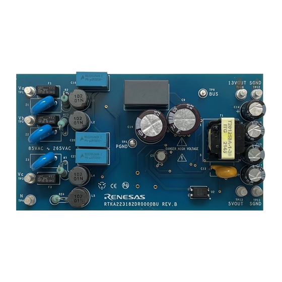
Page 4: Board Design
RTKA223182DR0000BU Demonstration Board Manual Board Design Photo Figure 2. RTKA223182DR0000BU Evaluation Board (Top) Figure 3. RTKA223182DR0000BU Evaluation Board (Bottom) R16UZ0074EU0101 Rev.1.01 Page 4 Mar 8, 2024... -
Page 5: Schematic Diagram
BAV21WS UNNAMED_2_RAA223182_I66_PIN1 UNNAMED_2_RAA223182_I66_PIN16 FSET 187K UNNAMED_2_RAA223182_I66_PIN3 UNNAMED_2_RAA223182_I66_PIN14 UNNAMED_2_RAA223182_I66_PIN13 UNNAMED_2_RAA223182_I66_PIN5 UNNAMED_2_RAA223182_I66_PIN12 VDET CDRV UNNAMED_2_RAA223182_I66_PIN6 UNNAMED_2_RAA223182_I66_PIN10 100PF UNNAMED_2_SMCAP_I182_A UNNAMED_2_SMCAP_I182_B 0.047UF RAA2231824GSP UNNAMED_2_EL817_I178_COL UNNAMED_2_EL817_I178_AN UNNAMED_2_EL817_I178_CAT EL817A-V DRAWN DATE: ENGINEER: DATE: AMNAT YAKAMNA 03/29/2023 JULIAN ZHU RELEASED BY: DATE: TITLE: Figure 4. RTKA223182DR0000BU Schematic... -
Page 6: Layout Guidelines
RTKA223182DR0000BU Demonstration Board Manual Layout Guidelines Proper layout is important to ensure a stable operation, good thermal behavior, EMI performance, and reliable operation for various operating environments. Pay attention to the following layout recommendations: ▪ Leave proper spacing. Recommend a minimum of 1.5mm between traces with voltage differences up to 400V and 2mm between traces with voltage differences up to 780V. -
Page 7: Bill Of Materials
RTKA223182DR0000BU Demonstration Board Manual Bill of Materials Manufacturer Reference Description Value Manufacturer Designator Part Number F1, F2, F3 Fuse 2A, 250V , Radial Bel Fuse RST 2 D2, D4 1A 1000V Bridge Rectifier 1A, 1000V, ABS Diodes Inc ABS10A-13 5.6V, 500mW, SOD-... - Page 8 RTKA223182DR0000BU Demonstration Board Manual Manufacturer Reference Description Value Manufacturer Designator Part Number R2, R7, Wire-wound Resistors 22, 5%, 1W, axial Yageo KNP100JR-73-22R R23, R24 40.2k, 1%, 1/16W, Thick Film Chip Resistor Generic Various 0603 Thick Film Chip Resistor Generic Various 8.25k, 1%, 1/16W,...
-
Page 9: Transformer Specifications
RTKA223182DR0000BU Demonstration Board Manual Transformer Specifications Figure 7. Transformer Specifications and Construction The transformer for the demonstration board is a customized part by ITG, and has the following key characteristics: ▪ Low cost E16 core ▪ Meet 7.0mm clearance and creepage distance ▪... -
Page 10: Typical Performance Graphs
RTKA223182DR0000BU Demonstration Board Manual Typical Performance Graphs = 121V AC ~500V AC , V = 12.5V, I = 800mA (max), V = 5V, I = 200mA (max), T = +25°C OUT1 OUT1 OUT2 OUT2 12.5V Output, 398Vac 5V Output, 398Vac 12.5V Output, 208Vac... -
Page 11: Short-Time Heavy Load
RTKA223182DR0000BU Demonstration Board Manual Short-Time Heavy Load The RTKA223182DR0000BU can support the short-time heavy load, as Figure 12 shows. The allowed operation time is limited by the capacitor on the OVL pin, as calculated by Equation 13 in the datasheet. A bigger OVL capacitor allows longer heavy-load operation. -
Page 12: Emi Performance
RTKA223182DR0000BU Demonstration Board Manual EMI Performance RTKA223182DR0000BU is compliant to the conducted EMI requirements of FCC Part 15 and CISPR22 Class B. Figure 16. 207V Phase-to-Phase, Line Figure 17. 207V Phase-to-Phase, Neutral Figure 18. 276V Phase-to-Phase, Line Figure 19. 276V... - Page 13 Renesas' products are provided only subject to Renesas' Terms and Conditions of Sale or other applicable terms agreed to in writing. No use of any Renesas resources expands or otherwise alters any applicable warranties or warranty disclaimers for these products.
Need help?
Do you have a question about the RTKA223182DR0000BU and is the answer not in the manual?
Questions and answers