Table of Contents
Advertisement
Quick Links
RTKA212831DR0000BU
The RTKA212831DR0000BU provides a simple
platform to demonstrate the performances of the
RAA212831. The RAA212831 is an integrated 72V
input voltage, 0.5A output load one synchronous buck
regulator with fixed switching frequency from 350kHz
and two 100mA, and 50mA output load linear
regulators LDOs. The buck can support a wide input
voltage range of 14V to 72V and adjusted output
voltage from 1.25V to 24V. The LDO_3V3 can support
a wide input voltage range of 6V to 12V, and the
output voltage is fixed at 3.3V. The LDO_5 can
support a wide input voltage range of 6V to 12V, and
the output voltage is fixed at 5V. It is designed for
small size and high integration electric-bike control
board power management. Integrated buck and
LDOs minimize the system components.
The Buck converter adopts peak current mode
control, providing 500mA current for load and
downstream LDO regulators, while the following
LDOs provide 5V and 3.3V regulated power sources
to the system. The current-mode buck converter
provides a fast transient response and cycle-by-cycle
switching current limit. All output voltages are fixed
internally with few external components.
The RAA212831 has a fixed frequency operation,
even the output terminal is light load condition,
therefore, the switching frequency is fixed during the
load variation. The RAA212831 can also use external
components to achieve standby function to control
buck output voltage as 6V or 12V. When the chip
wants to save more energy with LDOs operations
only, the external component can control buck output
voltage from 12V to 6V.
(a) Without External Standby Function
R16UZ0022EU0101 Rev.1.01
Jun 15, 2022
Features
▪ Buck Converter:
▪ 5V LDO Regulator:
▪ 3.3V LDO Regulator:
Specifications
This board is configured and optimized for the
following operating conditions:
▪ V
▪ VOUT = 6V~12V (For LDOs normal operations)
▪ IOUT_MAX = 0.5A
▪ VLDO_5V = 5V
▪ LDO_5V_MAX = 0.1A
▪ VLDO_3V3 = 3.3V
▪ ILDO_3V3_MAX = 0.05A
Figure 1. Typical Application Diagrams
Demonstration Board Manual
• 4.5V to 72V input voltage
• Adjustable output voltage from 1.25V to 24V
• 500mA output load capability
• 0.6Ω high-side MOSEFT r
• Fixed switching frequency 350kHz operation
• High side OCP, UVP, UVLO, OTP fault protection
• 6V to 12V input voltage
• Fixed output voltage 5V
• 100mA output load capability
• Current limit foldback function
• 6V to 12V input voltage
• Fixed output voltage 3.3V
• 50mA output load capability
• Current limit foldback function
= 14V to 72V (For VOUT is operated at 6V~12V)
IN
(b) with external standby function
© 2021 Renesas Electronics
DS(ON)
Page 1
Advertisement
Table of Contents

Related Manuals for Renesas RTKA212831DR0000BU


Summary of Contents for Renesas RTKA212831DR0000BU
- Page 1 Demonstration Board Manual RTKA212831DR0000BU Features The RTKA212831DR0000BU provides a simple platform to demonstrate the performances of the ▪ Buck Converter: RAA212831. The RAA212831 is an integrated 72V • 4.5V to 72V input voltage input voltage, 0.5A output load one synchronous buck •...
-
Page 2: Table Of Contents
RTKA212831DR0000BU Demonstration Board Manual Contents Functional Description ..............3 Operation Range . -
Page 3: Functional Description
Operation Range The RTKA212831DR0000BU demonstration board input voltage range is 14V to 72V. The output voltage is fixed at 12V when the EXTFB test point is high and 6V when the EXTFB test point is low. It is a simple setting for use. -
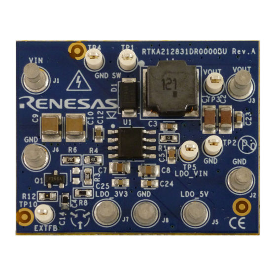
Page 4: Board Design
RTKA212831DR0000BU Demonstration Board Manual Board Design Figure 3. RTKA212831DR0000BU Demonstration Board (Top) Figure 4. RTKA212831DR0000BU Demonstration Board (Bottom) Layout Guidelines A good PCB layout is important to achieve expected performance. Consideration should be taken when placing the components and routing the trace to minimize the ground impedance and keep the parasitic inductance low. -
Page 5: Schematic Diagram
Schematic Diagram LDO_VIN LDO_VIN UNNAMED_3_SMCAP_I130_B UNNAMED_3_RAA212831_I160_7 VOUT 0.1UF LDO_5V 120UH LDO_5V UNNAMED_3_RAA212831_I160_3 LDO_3V3 VOUTN RAA212831 LDO_3V3 TP10 UNNAMED_3_NCHANNEL_I133_G EXTFB SI2342DS Figure 5. RTKA212831DR0000BU Board Circuit Schematic... -
Page 6: Bill Of Materials
RTKA212831DR0000BU Demonstration Board Manual Bill of Materials Ref Des Description Manufacturer Part Number IC SWITCHING REGULATOR, 8P, PSOP-8E, ROHS Renesas RAA212831GSP#AA0 COIL PWR INDUCTOR, SM, 8mm, 120µH, 20%, 1.15A, Wurth 74404084121 ROHS 1A 80V SCHOTTKY BARRIER RECTIFIER Diodes B180-13-F 6A, 8V, N-Channel (D-S) MOSFET... -
Page 7: Board Layout
RTKA212831DR0000BU Demonstration Board Manual Board Layout Figure 6. Top Layer Figure 7. Bottom Layer R16UZ0022EU0101 Rev.1.01 Page 7 Jun 15, 2022... -
Page 8: Typical Performance Graphs
RTKA212831DR0000BU Demonstration Board Manual Typical Performance Graphs = 56V, V = 6V, T = +25°C, unless otherwise noted. 6.03 VIN = 16V VIN = 24V VIN = 36V VIN = 48V 6.02 VIN = 56V VIN = 64V VIN = 72V 6.01... - Page 9 RTKA212831DR0000BU Demonstration Board Manual = 56V, V = 6V, T = +25°C, unless otherwise noted. 10V/Div 10V/Div 50mV/Div 2V/Div 200mA/Div 100mA/Div 100mA/Div VSTBY 500mV/Div 200µs/Div 200µs/Div Figure 14. Load Transient between 0.25A to 0.5A Figure 15. With External Standby Function at Full Load...
- Page 10 RTKA212831DR0000BU Demonstration Board Manual = 56V, V = 12V, T = +25°C, unless otherwise noted. 10V/Div 10V/Div 2V/Div 2V/Div 1V/Div 100mA/Div LDO5V 500mV/Div 100mA/Div LDO3V3 10ms/Div 2ms/Div Figure 20. Power-On at Full Load Figure 21. Power-On at Full Load with LDO Channels...
- Page 11 RTKA212831DR0000BU Demonstration Board Manual = VINLDO = 6V, VLDO5V = 5V, VLDO3V3 = 3.3V, T = +25°C, unless otherwise noted. (Cont.) 50mV/Div 50mV/Div LDOIN LDOIN 10mV/Div LDO3V3 20mV/Div LDO5V 10mA/Div 20mA/Div LDO3V3 LDO5V 200µs/Div 200µs/Div Figure 26. VLDO3V3 Load Transient between 0A to Figure 27.
-
Page 12: Ordering Information
RTKA212831DR0000BU Demonstration Board Manual Ordering Information Part Number Description RTKA212831DR0000BU RAA212831 Demonstration Board Revision History Revision Date Description 1.01 Jun 15, 2022 Updated Figures 3 and 4. 1.00 Sep 27, 2021 Initial release R16UZ0022EU0101 Rev.1.01 Page 12 Jun 15, 2022... - Page 13 Renesas' products are provided only subject to Renesas' Terms and Conditions of Sale or other applicable terms agreed to in writing. No use of any Renesas resources expands or otherwise alters any applicable warranties or warranty disclaimers for these products.
Need help?
Do you have a question about the RTKA212831DR0000BU and is the answer not in the manual?
Questions and answers