Advertisement
Safety Information

- Read the user manual before use and follow all safety information.
- Use the meter only as specified in this user manual. Otherwise meter protection may be impaired.
- Never use this meter on a circuit with voltages greater than 750Vrms @ 50/60 Hz.
- Do not operate the meter if the body or tests leads look damaged.
- Check the function selector range switch and make sure it is at the correct position before each measurement.
- Do not perform resistance and continuity test on a live circuit.
- Exercise extreme caution when measuring live systems with voltage greater than 60V DC or 30V AC.
- Use extreme care when working around bus bars and bare conductors.
- Do not use the meter in over range/overload conditions (OL).
- Change the battery when the
![]() symbol appears to avoid erroneous readings.
symbol appears to avoid erroneous readings.
 symbol appears to avoid erroneous readings.
Environmental Conditions:
Altitude up to 2000 meters.
Operating temperature: 0°C ~ 40°C, <80% RH, non-condensing
Storage temperature: -10°C ~ 60°C, <70% RH, battery removed
Pollution Degree: 2
Installation Categories III (600V), II (1000V)
Explanation of Symbols:
| Attention! Refer to operation Instructions. |
 | Dangerous voltage may be present at terminals. |
 | This instrument has double insulation. |
When servicing, use only specified replacement parts.
Specification
General Specification
Digital Display:
3 3/4 digits LCD display with maximum reading 3999
Analog Display:
Fast 42 segment analog bar graph display
Symbol and Scale range:
Automatic display according symbols and range input signal
Polarity:
 Displayed when negative signal applied to the input
Over Load:
 is Displayed when input signal exceeds measuring limit in 40A, resistance and continuity range.
In voltage, current and frequency range, this symbol will not be shown even the read reach the measuring limit. The measuring limit of these ranges are:
ACV: 750V
DCV: 1000V
ACA: 1000A
Hz: 10KHz
Sample Rate:
2 times/sec for digital data; 20 times/sec for analog bar
Low Battery Indication:
 displayed when the battery is below the required voltage
Power Source: 9V, NEDA1604 or 6F22 or 006P
Battery Life: 180 hrs typical (Alkaline)
Auto Power Off:
The meter will power itself OFF if there is no push button or rotary switch operation for 30 minutes.
To deactivate this function, press the "MAX MIN" button and keep it pressed down, then power up the probe.
Clamp opening size: 40mm
Dimension (L x W x H): 242 x 66 x 36 mm, 9.53 x 2.60 x1.42 inch
Weight: 400g, 14.10 OZ (battery included)
Accessory:
Instruction Manual, Carrying Case, Test lead, 9V Battery
Electrical Specification
The accuracy specification is defined as ±(...%reading+...count ) At 23±5, ≦80 %RH
ACA (400A/1000A Autorange)
| Range | Resolution | Accuracy | Overload Protection |
| 40A | 0.01A | ± ( 1.9%rdg + 5dgts ) 50 ~ 500Hz | 800Arms |
| 400A | 0.1A | 1000Arms | |
| 1000A | 1A |
ACV (Autorange)
| Range | Resolution | Accuracy | Input Impedance | Overload Protection |
| 400V | 0.1V | ±( 1.2%rdg + 5dgts ) 50 ~ 500Hz | 10MΩ | 1200Vpp |
| 750V | 1V |
DCV (Autorange)
| Range | Resolution | Accuracy | Input Impedance | Overload Protection |
| 400V | 0.1V | ±( 0.75%rdg + 2dgts ) | 10MΩ | 1200Vpp |
| 1000V | 1V |
Ohm (Resistance) (Autorange)
| Range | Resolution | Accuracy | Overload Protection |
| 400Ω | 0.1Ω | ± ( 1%rdg + 3dgts ) | 600Vrms |
| 4000Ω | 1Ω |
 (Diode)
| Range | Active Region | Overload Protection |
| | 0.6mA | 600Vrms |
Continuity (  )
)
| Range | Active Region | Overload Protection |
| <100 Ω | 600Vrms |
Frequency (Hz) (Autorange)
| Function | Range | Resolution | Sensitivity | Accuracy |
| A-Hz | 4k | 1Hz | 2Arms | (20~10KHz) ±( 0.1%rdg + 1dgts ) |
| 10k | 10Hz | 5Arms | ||
| V-Hz | 4K | 1Hz | 5Vrms | (10~10KHz) ±( 0.1%rdg + 1dgts ) |
| 10K | 10Hz | 10Vrms |
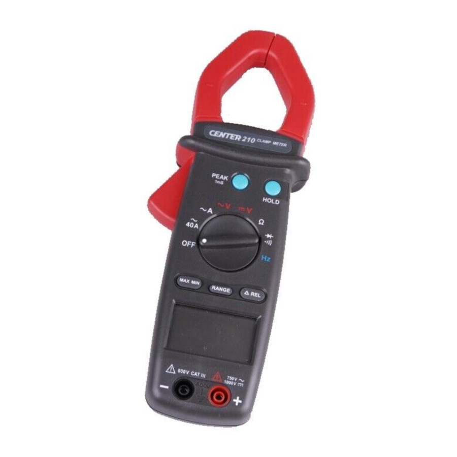
Instrument Familiarization
Part and Position

- Current Sensing Clamp
- Clamp opening handle
- Function select dial
- Hold Button
- Peak Hold Button
- Maximun Minimun Button
- Range button
- Relative Button
- LCD Display
- "COM" Terminal
- " + " test Terminal
Symbol Definition

Measuring Instruction
AC Current Measurement

Switch the main function selector to ~A range.
Open the clamp by pressing the jaw-opening handle and insert the cable to be measured into the jaw.
Close the clamp and get the reading from the LCD panel.
Note:
Before this measurement, disconnect the test lead with the meter for safety.
In some occasion that the reading is hard to read, push the HOLD button and read the result later.
ACV measurement

Switch the main function selector to ~V range.
Connect red test lead to "+" terminal and black one to the " COM " terminal.
Measure the voltage by touch the test lead tips to the test circuit where the value of voltage is needed.
Read the result from the LCD panel.
DCV measurement

Switch the main function selector to  range.
Connect red test lead to "+" terminal and black one to the " COM " terminal.
Measure the voltage by touch the test lead tips to the test circuit where the value of voltage is needed.
Read the result from the LCD panel.
Resistance measurement

Switch the main function to "  " range, check the power line is disconnected from the system.
Connect red test lead to "+" terminal and black one to the " COM " terminal.
Connect tips of the test leads to the points where the value of the resistance is needed.
Read the result from the LCD panel.
Note:
When take resistance value from a circuit system, make sure the power is cut off and all capacitors need to be discharged.
Continuity Test

Switch the main function to "  " range, check the power line is disconnected from the system.
Connect red test lead to "+" terminal and black one to the " COM " terminal.
Connect tips of the test leads to the points where the conduction condition needed.
If the resistance is under 100Ω, the beeper will sound continuously.
Frequency measurement from the terminals

Switch the main function to "Hz " range.
Connect red test lead to "+" terminal and black one to the " COM " terminal.
Connect tip of the test leads to the points where the frequency of the voltage signal is needed.
Read the Result from the LCD panel.
Frequency measurement with the clamp

Switch the main function selector to" Hz " range.
Open the clamp by pressing the clamp-opening handle and insert the cable to be measured into the clamp.
Close the clamp and get the reading form the LCD panel.
Note:
When doing frequency measurement, user should either use the terminal signal or clamp signal but not both. If both sources are applied an error reading will occur.
Button Operation
- Data Hold Function:
At any time, the user can hold the present reading by press the "Hold" button and release the held data by press it again. - Peak Hold Function:
This meter is built with 1ms peak hold function at ACA, ACV and DCV ranges.
Before the user wants to perform a peak hold operation, he must finish calibration process at first.
To invoke the calibration operation, the user must press and hold the peak button for 2 seconds. After that "CAL" will display on the LCD and the offset will be calculated and kept in the meter.
After the calibration the user can choose P+ or P- by press peak hold button to keep the peak reading. Press the peak button for 2 seconds will return the meter back to normal operation.
Once the function range is changed, the meter will need another calibration for peak measurement. - MAX/MIN Function:
Press the "MAX/MIN" button once will set the meter to MAX mode.
Press it once again will set the meter to MIN mode.
Press it once again and meter will display the present reading and still keep track of the MAX and MIN change. This mode will also indicated by blinking "MAX MIN" symbol.
Press the "MAX/MIN" button for more than 2 seconds will set the meter back to normal operation. - REL Function:
Press the "REL" button will change the zero to the present reading and the relative value will show on the LCD.
Press it once again and meter will display the relative zero point. This mode will also indicated by blinking "REL" symbol.
Press the "REL" button for more than 2 seconds will set the meter back to normal operation. - Range Function:
Press the " RANGE " button to select the manual range mode, and the![]() annunciator turn on and the meter remains in the same range it was.
annunciator turn on and the meter remains in the same range it was.
To exit the manual range mode and return to auto range mode, press and hold down " RANGE" button for 1 seconds.
Note: This function is disabled in frequency range.
 annunciator turn on and the meter remains in the same range it was.
Battery Changing
- When the battery voltage drop below proper operation range the
![]() symbol will appear on the LCD display and the battery need to be changed.
symbol will appear on the LCD display and the battery need to be changed. - Before changing the battery, switch the main dial to "OFF "and disconnect test leads.
Open the back cover by a screwdriver.
Replace the old batteries with a new 9V battery. - Close the back cover and fasten the screw.
 symbol will appear on the LCD display and the battery need to be changed.
Maintenance

Before open the meter, disconnect both test lead and never uses the meter before the cover is closed

To avoid contamination or static damage, do not touch the circuit board without proper static protection.
*REMARK:
- If the meter is not going to be used for a long time, take out the battery and do not store the meter in high temperature or high humidity environment.
- When take current measurement, keep the cable at the center of the clamp will get more accurate test result.
- Repairs or servicing not covered in this manual should be performed only by qualified personal.
*CLEANING:
Periodically wipe the case with a dry cloth. Do not use abrasives or solvents on this instruments.
CENTER TECHNOLOGY CORP.
4 / F NO. 415, Jung-Jeng Rd., 238 Shu-Lin Chien, Taipei, Taiwan
TEL: 886-2-26763926
FAX: 886-2-26763925
E-Mail: center@centertek.com
http://www.centertek.com
Documents / Resources
References
Download manual
Here you can download full pdf version of manual, it may contain additional safety instructions, warranty information, FCC rules, etc.
Advertisement


Need help?
Do you have a question about the 210 and is the answer not in the manual?
Questions and answers