Table of Contents
Advertisement
Quick Links
Advertisement
Table of Contents

Related Manuals for Center 28


Summary of Contents for Center 28
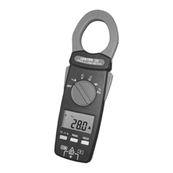
- Page 1 AC TRMS CLAMP METER...
-
Page 2: Table Of Contents
TABLE OF CONTENTS SAFETY INFORMATION ............1 2. GENERAL SPECIFICATION ............1 3. ELECTRICAL SPECIFICATION ............2 3-1 Direct Voltage................2 3-2 Direct Voltage (Peak Mode)............2 3-3 Alternating Voltage..............2 3-4 Alternating Voltage (Peak Mode)..........2 3-5 Alternating Current..............3 3-6 Alternating Current (Peak Mode)..........3 3-7 Resistance(Ω)................3 3-8 Continuity( )................3... -
Page 3: Safety Information
TRMS Clamp Meter SAFETY INFORMATION Do not operate the tester if the body of meter or the test lead look broken. Check the main function dial and make sure it is at the correct position before each measurement. Do not perform resistance and continuity test on a live power system. Do not apply voltage between the test terminals and test terminal to ground that exceed the maximum limit record in this manual. -
Page 4: Electrical Specification
TRMS Clamp Meter Auto Power Off: If there is no key or dial operation for 10 minutes, the meter will power itself off to save battery consumption. This function can be disabled by press and hold the “HOLD ” button then power the unit on. Over Load: When the signal larger than the maximum will be show Maximum jaw opening:... -
Page 5: Alternating Current
TRMS Clamp Meter 3-5 Alternating Current ( Range Resolution Accuracy Overload Protection 1.9%±5dgts(50~60Hz) 600A 0.1A 1000Arms 2.5%±5dgts(45~500Hz) 1000A 3-6 Alternating Current (Peak Model) Overload Protection Range Resolution Accuracy ±2.9% ± 5dgts 1000Arms 1000A 3-7 Resistance () Range Resolution Accuracy Overload Protection 600... -
Page 6: Description Of The Instrument
TRMS Clamp Meter 4. DESCRIPTION OF THE INSTRUMENT 4-1 Description Of The Display Auto Power Off Indication Polarity Indication Low Battery Indication Alternative Source Indication Direct Source Indication Current Measurement Indication Voltage Measurement Indication Capacitance Measurement Indication Data Hold Indication Peak Data Indication Continuity Test Indication /M/K... -
Page 7: Description Of Front And Rear
TRMS Clamp Meter 4-2 Description Of Front And Rear Current Sensing Clamp ○ Safety Protection Ring ○ Clamp Opening Handle ○ Function Select Dial ○ LCD Display ○ AC/DC Voltage & / & Hz/% ○ Select Button Peak Hold Button ○... -
Page 8: Button Instruction
TRMS Clamp Meter 5. BUTTON INSTRUCTION 5-1 HOLD Function It is possible to freeze the value displayed by pressing on the "HOLD" button. To deactivate this function, press the "HOLD" button a second time. 5-2 PEAK Function If you press on the "PEAK" button , the display will show " "... -
Page 9: Dc Voltage Measurement
TRMS Clamp Meter 6-2 DC Voltage Measurement: Switch the main function selector range. Connect red test lead to “ + ” terminal and black one to the “COM”terminal. Measure the voltage by touch the test lead tips to the test circuit where the value of voltage is needed. -
Page 10: Resistance Measurement
TRMS Clamp Meter 6-4 Resistance Measurement Switch the main function to range. Connect red test lead to “+”terminal and black one to the“COM”minal. Connect tip of the test leads to the points where the value of the resistance is needed. Read the result from the LCD panel. -
Page 11: Capacitance Measurement
TRMS Clamp Meter 6-6 Capacitance Measurement Switch the main function selector to range. Connect red test lead to “+” terminal and black one to the “COM” terminal. Connect tips of the test leads to the capacitor being tested. Read the capacitance value on LCD. Note: To avoid damage to the meter, disconnect circuit power and discharge... -
Page 12: Measurement Of Duty Cycle
TRMS Clamp Meter 6-9 Measurement Of Duty Cycle (%) Switch the main function to range. Press button to range. Connect red test lead to“+”terminal and black one to the “COM” terminal. Place the touch prods in contact with the points whose % is to be measured. -
Page 13: Maintenance
(2) When take current measurement, keep the cable at the center of the clamp will get more accurate test result. (3) Repairs or servicing not covered in this manual should be performed only by qualified personal. - Page 14 CENTER TECHNOLOGY CORP. 4F, NO.415, Jung-Jeng Rd., Shu-Lin Dist., New Taipei City 238, Taiwan TEL : 886-2-26763926 E-Mail : center@centertek.com FAX : 886-2-26763925 http : / / www.centertek.com GCA00028-02000...
Need help?
Do you have a question about the 28 and is the answer not in the manual?
Questions and answers