Advertisement
DESCRIPTION OF THE INSTRUMENT
Description Of The Display

 | Auto Power Off Indication |
 | Polarity Indication |
 | Low Battery Indication |
 | Alternative Source Indication |
 | Direct Source Indication |
 / / | Current / Voltage Measurement Indication |
 | Danger Voltage Indication |
 | Data Hold Indication |
 | Min/Max Indication |
 | Continuity Test Indication |
| M/ K | Measurement Unit |
 | Resistance measurement indication |
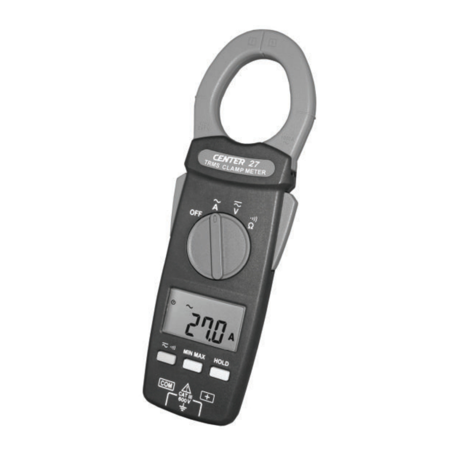
Description Of Front And Rear

- Current Sensing Clamp
- Safety Protection Ring
- Clamp Opening Handle
- Function Select Dial
- LCD Display
- AC/DC Voltage &
![]() Select Button
Select Button - Min/Max Button
- Data Hold Button
- COM Input Terminal
- Positive Input Terminal
- Battery Cabinet
 Select Button
BUTTON INSTRUCTION
HOLD Function
It is possible to freeze the value displayed by pressing on the "HOLD" button. To deactivate this function, press the "HOLD" button a second time.
MIN/MAX Function
Press the MIN/MAX button to enter the Min/Max mode. Press the MIN/MAX button, to read Max, Min, and current reading in sequence. Press the MIN/MAX button for 2 seconds, to exit the Min/Max mode.
AC/DC Voltage Select and  Select Button
Press ![]() button to select function.
button to select function.
To select function AC or DC in Voltage range.
To select continuity or Resistance in ![]() range.
range.
MEASURING INSTRUCTION
AC Voltage Measurement
Switch the main function selector to ![]() range.
range.
Connect red test lead to"+" terminal and black one to the "COM"terminal.
Measure the voltage by touch the test lead tips to the test circuit where the value of voltage is needed.
Read the result from the LCD panel.

DC Voltage Measurement
Switch the main function selector to ![]() range.
range.
Connect red test lead to "+" terminal and black one to the "COM"terminal.
Measure the voltage by touch the test lead tips to the test circuit where the value of voltage is needed.
Read the result from the LCD panel.
Note:
When the reading is exceeding 30V in ACV or DCV, the  symbol will be displayed on.

AC Current Measurement
Switch the main function selector to ![]() range.
range.
Open the clamp by pressing the jaw-opening handle and insert the cable to be measured into the jaw.
Close the clamp and get the reading from the LCD panel.
Note:
Before this measurement, disconnect the test lead with the meter for safety.
In some occasion that the reading is hard to read, push the HOLD button and read the result later.

Resistance Measurement
Switch the main function to  range.
Connect red test lead to "+"terminal and black one to the "COM" terminal.
Connect tip of the test leads to the points where the value of the resistance is needed.
Read the result from the LCD panel.
Note:
When take resistance value from a circuit system, make sure the power is cut off and all capacitors need to be discharged.

Continuity Test With Buzzer
Switch the main function to  range.
Connect red test lead to"+"terminal and black one to the "COM" terminal.
Connect tip of the test leads to the points where the conduction condition needed.
If the resistance is under 100Ω, the beeper will sound continuously.

BATTERY CHANGING

- When the battery voltage drop below proper operation range the
![]() symbol will appear on the LCD display and the battery needs to be changed.
symbol will appear on the LCD display and the battery needs to be changed. - Before changing the battery, switch the main dial to "OFF "and disconnect test leads.
![]() Open the back cover by an appropriate tool.
Open the back cover by an appropriate tool.- Replace the old battery with new 3V (CR2032) battery.
- Close the Battery cover.
MAINTENANCE

Before open the meter, disconnect both test lead and never uses the meter before the cover is closed.

To avoid contamination or static damage, do not touch the circuit board without proper static protection.
REMARK
- If the meter is not going to be used for a long time, take out the battery and do not store the meter in high temperature or high humidity environment.
- When take current measurement, keep the cable at the center of the clamp will get more accurate test result.
- Repairs or servicing not covered in this manual should be performed only by qualified personal.
CLEANING
Periodically wipe the case with a dry cloth.
Do not use abrasives or solvents on these instruments.
GENERAL SPECIFICATION
Digital Display:
4 digital liquid crystal(LCD), Maximum reading 6000.
Polarity:
When a negative signal is applied, the ![]() signal appears.
signal appears.
Low Battery Indication:
When the battery is under the proper operation range, ![]() will appear on the LCD display. Sample Rate: 2 times/sec.
will appear on the LCD display. Sample Rate: 2 times/sec.
Power Source:
CR2032 (3VDC) X 1
Typical battery Life: 24 hours (without buzzer)
Auto Power Off:
If there is no key or dial operation for 10 minutes, the meter will power itself off to save battery consumption. This function can be disabled by press and hold the "HOLD " button then power the unit on.
Over Load:
When the signal larger than the maximum will be show  .
.
Maximum jaw opening:
 40 mm
40 mm
Dimensions:
207 x 66 x 26 mm
Weight:
Approx. 153g (with battery)
Accessories:
Carrying case, Battery, Test Lead & Instruction Manual.
ELECTRICAL SPECIFICATION
The accuracy specification is defined as ±[...%reading+...count ] at 23±5°C, ≦80 %RH. True RMS for VAC and AAC accuracy are specified from 5% to 100% of range, crest factor CF <1.6 at full scale
& CF < 3.2 at half scale.
Direct Voltage ( ![]() )
)
| Range | Resolution | Accuracy | Overload Protection |
| 6V | 0.001V | 1% ± 2dgts | 600Vrms |
| 60V | 0.01V | ||
| 600V | 0.01V |
Input impedance: 10 M
Alternating Voltage ( ![]() )
)
| Range | Resolution | Accuracy | Overload Protection |
| 6V | 0.001V | 1.2% ± 5dgts (50~500Hz) | 600Vrms |
| 60V | 0.01V | ||
| 600V | 0.01V |
LCD displays 0 when the reading < 20counts (6V range only)
Input impedance: 10 M
Alternating Current ( ![]() )
)
| Range | Resolution | Accuracy | Overload Protection |
| 600A | 0.1A | 1.9% ± 5dgts(50~60Hz) 2.5% ± 5dgts(45~500Hz) | 1000Arms |
| 1000A | 1A |
Resistance 
| Range | Resolution | Accuracy | Overload Protection |
600 | 0.1 | 1% ± 2dgts | 600Vrms |
6K | 0.001K | ||
60K | 0.01K | ||
600K | 0.1K |
Continuity 
| Range | Resolution | Accuracy | Overload Protection |
600 | 0.1 | 1% ± 2dgts | 600Vrms |
 | Ohm function Buzzer<100 | ||
SAFETY INFORMATION
Do not operate the tester if the body of meter or the test lead look broken.
Check the main function dial and make sure it is at the correct position before each measurement.
Do not perform resistance and continuity test on a live power system. Do not apply voltage between the test terminals and test terminal to ground that exceed the maximum limit record in this manual.
Keep the fingers after the protection ring when measuring through the test lead.
Chang the battery when the ![]() symbol appears to avoid incorrect data.
symbol appears to avoid incorrect data.
Environmental Conditions
Operation Temperature: 0°C to 40°C(32°F to 104°F); < 80% RH
Storage Temperature: -10°C to 60°C(14°F to 140°F); < 70% RH
Explanation Symbols
 Attention refer to operation Instructions.
 Dangerous voltage may be present at terminals.

This instrument has double insulation.
Documents / ResourcesDownload manual
Here you can download full pdf version of manual, it may contain additional safety instructions, warranty information, FCC rules, etc.
Advertisement


Need help?
Do you have a question about the 27 and is the answer not in the manual?
Questions and answers