
Related Manuals for Center 232


Summary of Contents for Center 232
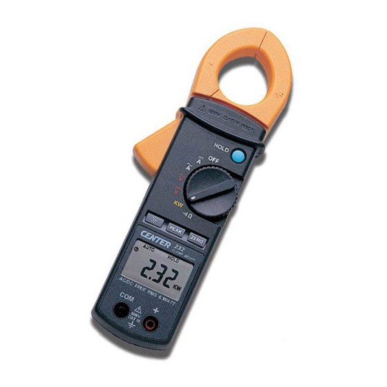
- Page 1 CLAMP METER 600V CAT 600A HOLD PEAK ZERO 600V CAT III AC\DC TRUE RMS & WATT...
-
Page 2: Table Of Contents
CONTENTS TITLE PAGE Safety Information ………………………………..…………..….1 Environmental Conditions………………………………….…..….…. 1 Explanation of Symbols……………….………………….…………… 1 Specification………..……………………………………………… 2 General Specification……………………...………………………….. 2 Electrical Specification……………………………...…………………. 3 III. Instrument Familiarization……………..………………………4 Symbol Definition………………………………………………………. 4 Part and Position……………….…………………….…………….…..4 Measuring Instruction……………..………..….……………...5 4.1 Current Measurement…………………...……………...………… 5 4.2 Voltage Measurement…………………………...………………... 6 4.3 Resistance Measurement &... -
Page 3: Safety Information
Safety Information – Read first • Read the user manual before use and follow all safety information. • Use the meter only as specified in this user manual. Otherwise meter protection may be impaired. • Never use this meter on a circuit with voltages greater than 650Vrms @ 50/60 Hz. -
Page 4: Specification
II. Specification General Specification: Digital Display: 4 digits LCD display with maximum reading 9999 Symbol and Scale range: Automatic display according symbols and range input signal. Polarity: Displayed when negative signal applied to the input. Over Load: is Displayed when input signal exceeds measuring limit. Sample Rate: 2.5 times/sec Low Battery Indication: displayed when the battery is below the required voltage. -
Page 5: Electrical Specification
Electrical Specification: The accuracy specification is defined as ±(…%reading+…count ) At 23 ±5℃, ≦80 %RH True RMS for ACV and ACA accuracy are specified from 5% to 100% of range. accuracy add ±(1%rdg) on Crest Factor 1.4<CF<3 at full scale & CF<6 at half scale. Overload Range Resolution... -
Page 6: Instrument Familiarization
III. Instrument Familiarization: Symbol Definition: Auto range indication Peak detect indication Low battery indication Data hold indication Zero indication Direct source indication Resistance measurement Auto power off indication with continuity beeper Alternative indication indication Voltage measurement indication Polarity indication Current measurement indication Watt measurement indication Part and Position :... -
Page 7: Measuring Instruction
IV. Measuring Instruction: 4.1 Current Measurement: Switch the main function selector to “ACA“ current range. Open the clamp by pressing the jaw-opening handle and insert the cable to be measured into the jaw. Switch the main function selector to “DCA” range. Wait for the reading to stabilize then press ZERO button to null the reading. -
Page 8: Voltage Measurement
4.2 Voltage Measurement: Switch the main function selector to “ACV” or “DCV” range. Connect red test lead to “+” terminal and black one to the “ COM ” terminal. Measure the voltage by touch the test lead tips to the test circuit where the value of voltage is needed. -
Page 9: Resistance Measurement & Continuity Test
4.3 Resistance Measurement and Continuity Test: Switch the main function to “ ” range, check power line disconnected from the system. Connect red test lead to “+” terminal and black one to the “ COM ” terminal. 600V CATIII 600A Connect tips of the test leads to the HOLD points where the value of the resistance... -
Page 10: Power Measurement
4.4 Power Measurement: Switch the main function selector to “KW” range. Open the clamp by pressing the jaw-opening handle and insert the cable to be measured into the jaw. Connect red test lead to “+” terminal and black one to the “ COM ” terminal. -
Page 11: Battery Changing
Back Light Function: Press the “Back Light” button will turn back light on and Press it once again will turn off. The meter will turn back light off if there is no push “Back Light” button for 30 seconds. ZERO Function: Press the “ZERO”... -
Page 12: Maintenance
When take current measurement, keep the cable at the center of the clamp will get more accurate test result. Repairs or servicing not covered in this manual should be performed only by qualified personal. - Page 13 CENTER TECHNOLOGY CORP. 4 / F NO. 415, Jung-Jeng Rd., 238 Shu-Lin, Taipei, Taiwan TEL : 886-2-26763926 E-Mail : center@centertek.com FAX : 886-2-26763925 http : / / www.centertek.com 232-00...
Need help?
Do you have a question about the 232 and is the answer not in the manual?
Questions and answers