Table of Contents
Advertisement
Quick Links
Advertisement
Table of Contents

Subscribe to Our Youtube Channel
Related Manuals for Center 261


Summary of Contents for Center 261
- Page 1 TRMS AC/DC LOW CURRENT CLAMP METER...
- Page 3 261-00 MAY. 105...
-
Page 4: Table Of Contents
TABLE OF CONTENTS 1. SAFETY INFORMATION…………………………………..1 2. GENERAL SPECIFICATION……………………………2 3. ELECTRICAL SPECIFICATION……………………………3 4. DESCRIPTION OF THE INSTRUMENT……………………6 4-1 Description of the display……………………………..6 4-2 Description of front and rear…………………………….7 5. BUTTON INSTRUCTION……………………………………8 5-1 HOLD function…….………………………………………8 5-2 Shift function……………………………………………8 5-3 ZERO function…….………………………………………8 5-4 BACKLIGHT function….…………………………………8 6. -
Page 5: Safety Information
TRMS AC/DC Low Current Clamp Meter SAFETY INFORMATION Do not operate the tester if the body of meter or the test lead looks broken. Check the main function dial and make sure it is at the correct position before each measurement. Do not perform resistance and continuity test on a live power system. -
Page 6: General Specification
TRMS AC/DC Low Current Clamp Meter 2. GENERAL SPECIFICATION Digital Display: 4 digital liquid crystal (LCD), maximum reading 6000. Polarity: When a negative signal is applied, the signal appears. Low Battery Indication: When the battery is under the proper operation range, will appear on the LCD display. -
Page 7: Electrical Specification
TRMS AC/DC Low Current Clamp Meter 3. ELECTRICAL SPECIFICATION The accuracy specification is defined as ± ( percent of reading + digit ) at 23±5°C, ≦80 %RH. DCmA Range Resolution Accuracy 4000mA 2.0% + 5dgts ACmA (True RMS) Accuracy Range Resolution 50~500Hz 4000mA... - Page 8 TRMS AC/DC Low Current Clamp Meter AC+DC A (True RMS) Accuracy Range Resolution 50~500Hz 40.00A 0.01A 2.5% + 5dgts 100.0A 4.5% + 5dgts 0.1A 200.0A 8.5% + 5dgts Range Resolution Accuracy 6.000V 0.001V 60.00V 0.01V 1.0% + 2dgts 600.0V 0.1V Input impedance: 1 M...
- Page 9 TRMS AC/DC Low Current Clamp Meter Capacitance Range Resolution Accuracy 1.000uF 0.001uF 10.00uF 0.01uF 3.0% + 8dgts 100.0uF 0.1uF 1000uF Diode test Range Resolution Accuracy 2.000V 0.001V 2.0% + 5dgts Resistance () Range Resolution Accuracy 600.0 0.1 6.000K 0.001K 1.0% + 3dgts 60.00K...
-
Page 10: Description Of The Instrument
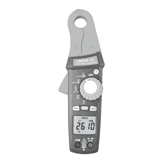
TRMS AC/DC Low Current Clamp Meter 4. DESCRIPTION OF THE INSTRUMENT 4-1 Description of the display: Auto power off indication Polarity indication Low battery indication Alternative source indication Direct source indication AC+DC measurement indication Current measurement indication Voltage measurement indication Capacitance measurement indication Diode measurement indication Resistance measurement indication... -
Page 11: Description Of Front And Rear
TRMS AC/DC Low Current Clamp Meter 4-2 Description of front and rear: ○ ○ Current sensing clamp Safety protection ring ○ ○ Backlight button Clamp opening handle ○ ○ Function select dial ZERO button ○ ○ Shift function button Data hold button ○... -
Page 12: Button Instruction
TRMS AC/DC Low Current Clamp Meter 5. BUTTON INSTRUCTION 5-1 HOLD function: It is possible to freeze the value displayed by pressing the "HOLD" button. Press the "HOLD" button again to exit the Hold mode. 5-2 Shift Function: Press " "... -
Page 13: Measuring Instruction
TRMS AC/DC Low Current Clamp Meter 6. MEASURING INSTRUCTION 6.1 DCmA、DCA measurement: With the clamp disconnected from any conductor, switch the function selector to DCmA or DCA range. Press "ZERO" button to zero reading. Open the clamp by pressing the jaw-opening handle and insert cable measured into the jaw. -
Page 14: Dcv Measurement
TRMS AC/DC Low Current Clamp Meter INCORRECT CORRECT 6-3 DCV measurement: WARNING! Maximum Input Voltage is 660V AC/DC. Do not attempt to take any voltage measurement that may exceed this maximum to avoid electrical shock hazard and/or damage to this instrument. Switch the main function selector... -
Page 15: Acv、Ac+Dcv Measurement
TRMS AC/DC Low Current Clamp Meter 6-4 ACV、AC+DCV measurement: WARNING! Maximum Input Voltage is 660V AC/DC. Do not attempt to take any voltage measurement that may exceed this maximum to avoid electrical shock hazard and/or damage to this instrument. Switch main function selector to ACV or AC+DCV... -
Page 16: Diode Test Measurement
TRMS AC/DC Low Current Clamp Meter capacitance. Use the DC voltage function to confirm that the capacitor is discharged. 6-6 Diode test measurement: Switch the main function selector to Diode range. Connect red test lead to “” terminal and black one to the "COM"... -
Page 17: Continuity Test With Buzzer
TRMS AC/DC Low Current Clamp Meter 6-8 Continuity test with buzzer: Switch the main function to range. Connect red test lead to “” terminal and black one to the "COM" terminal. Connect tip of the test leads to the points where the conduction condition needed. -
Page 18: Battery Replacement
TRMS AC/DC Low Current Clamp Meter 7. BATTERY REPLACEMENT When the battery voltage drops below proper operation range, the symbol will appear on the LCD display and the battery needs to be replaced. Before changing the battery, switch the main dial to “OFF ”and disconnect test leads. -
Page 19: Maintenance
When taking current measurement, keep the cable at the center of the clamp will get more accurate test result. Repairs or servicing not covered in this manual should be performed only by qualified personal. - Page 20 MEMO:...
- Page 21 MEMO:...
- Page 22 MEMO:...
- Page 24 CENTER TECHNOLOGY CORP. 4F, NO.415, Jung-Jeng Rd., Shu-Lin Dist., New Taipei City 238, Taiwan TEL : 886-2-26763926 E-Mail : center@centertek.com FAX : 886-2-26763925 http : / / www.centertek.com GCA000261-02000...
Need help?
Do you have a question about the 261 and is the answer not in the manual?
Questions and answers