
Related Manuals for Center 212


Summary of Contents for Center 212
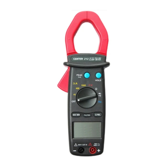
- Page 1 True Rms 1000 PEAK HOLD 1000 1000 1000 600V AC\DC CLAMP METER...
-
Page 2: Table Of Contents
CONTENTS TITLE PAGE I. Safety Information ………………………………………...1 Environmental Conditions……………………………………….…. 1 Explanation of Symbols……………….……………………………. 1 II. Specification …………………………………………………... 2 General Specification……………………...………………………... 2 Electrical Specification……………………………...……………… 2 III. Instrument Familiarization …………………………..3 Symbol Definition……………………………………………………. 4 Part and Position……………….…………………….……………..4 IV. Measuring Instruction ……………………………...…. 5 4.1 Current Measurement…………………………...……………...…….. -
Page 3: Safety Information
Safety Information – Read first • Read the user manual before use and follow all safety information. • Use the meter only as specified in this user manual. Otherwise meter protection may be impaired. • Never use this meter on a circuit with voltages greater than 750Vrms @ 50/60 Hz. -
Page 4: Specification
II. Specification General Specification: Digital Display: 3 3/4 digits LCD display with maximum reading 3999 Analog Display: Fast 40 segment analog bar graph display Symbol and Scale range: Automatic display according symbols and range input signal Polarity: Displayed when negative signal applied to the input Over Load: is Displayed when input signal exceeds measuring limit in 40A, 400A, resistance and continuity range. - Page 5 Range Resolution Accuracy Overload Protection 0.01A 50 ~ 60Hz 60 ~ 500Hz 1200Arms 400A 0.1A ± ( 1.9%rdg + 5dgts ) ± ( 2.5%rdg + 5dgts ) 1000A Range Resolution Accuracy Overload Protection 0.01A ± ( 2.5%rdg + 10dgts ) 1200Arms 400A 0.1A...
-
Page 6: Instrument Familiarization
III. Instrument Familiarization: Symbol Definition: Relative indication Positive Peak detect indication Continuity with beeper Alternative Diode function indication Auto Power Off indication Negative Peak detect indication Data Hold indication Manual range indication Resistance measurement indication Voltage & Current measurement indication Frequency Measurement indication Analog Bar display Direct Source indication... -
Page 7: Measuring Instruction
IV. Measuring Instruction: 4.1 Current Measurement: Switch the main function selector to proper current range. Open the clamp by pressing the jaw-opening handle and insert the cable to be measured into the jaw. Choose AC current measurement by pressing the AC/DC button for ACA reading. -
Page 8: Voltage Measurement
4.2 Voltage measurement: Switch the main function selector to voltage range. Connect red test lead to “+” terminal and black one to the “ COM ” terminal. Choose AC or DC by pressing the AC/DC button. Measure the voltage by touch the test lead tips to the test circuit where the value of voltage is needed. - Page 9 DCV measurement 1000 PEAK HOLD 1000 1000 1000 600V...
-
Page 10: Resistance Measurement
4.3 Resistance measurement: Switch the main function to “ ” range, check the power line is disconnected from the system . Connect red test lead to “+” terminal and black one to the “ COM ” terminal. Connect tips of the test leads to the points where the value of the resistance is needed. -
Page 11: Continuity Test
4.4 Continuity Test: Switch the main function to ” ” range, check the power line is disconnected from the system. Connect red test lead to “+” terminal and black one to the “ COM ” terminal. Connect tips of the test leads to the points where the conduction condition needed. -
Page 12: Diode Test
Diode Test: Switch the main function to ” ” range, check the power line is disconnected from the system. Connect red test lead to “+” terminal and black one to the “ COM ” terminal. Connect tips of red test lead to the anode side and black test lead to the cathode side of the diode being tested. -
Page 13: Frequency Measurement From The Terminals
4.5 Frequency measurement from the terminals: Switch the main function to “ ” range. Connect red test lead to “+” terminal and black one to the “ COM ” terminal. Connect tip of the test leads to the points where the frequency of the voltage signal is needed. -
Page 14: Frequency Measurement With The Clamp
4.6 Frequency measurement with the clamp: Switch the main function selector to“ ” range. Open the clamp by pressing the clamp-opening handle and insert the cable to be measured into the clamp. Close the clamp and get the reading form the LCD panel. Note: When doing frequency measurement, user should either use the terminal signal or clamp signal but not both. -
Page 15: Button Operation
4.7 Button Operation: Data Hold Function: At any time, the user can hold the present reading by press the “Hold” button and release the held data by press it again. Peak Hold Function: This meter is built with 1ms peak hold function at ACA, ACV, DCA and DCV ranges. -
Page 16: Battery Changing
When take current measurement, keep the cable at the center of the clamp will get more accurate test result. Repairs or servicing not covered in this manual should be performed only by qualified personal. - Page 17 CENTER TECHNOLOGY CORP. 4 / F NO. 415, Jung-Jeng Rd., 238 Shu-Lin, Taipei, Taiwan TEL : 886-2-26763926 E-Mail : center@centertek.com FAX : 886-2-26763925 http : / / www.centertek.com 212-00...
Need help?
Do you have a question about the 212 and is the answer not in the manual?
Questions and answers