
Related Manuals for Center 222


Summary of Contents for Center 222
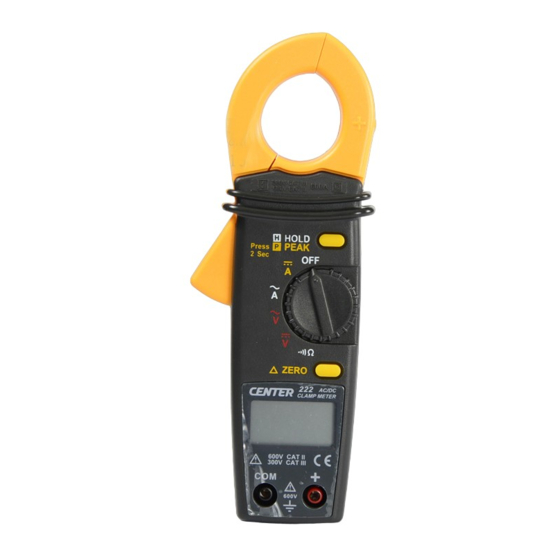
- Page 1 600V CAT II 600A 300V CAT III HOLD Press PEAK 2 Sec ZERO 600V CAT II 300V CAT III 600V MINI AC/DC CLAMP METER...
-
Page 2: Table Of Contents
CONTENTS TITLE PAGE I. Safety Information ………………………………... 1 Environmental Conditions…………………………….….. 1 Explanation of Symbols……………….…………………. 1 II. Specification ……………………………………….…. 2 General Specification……………………………………. 2 Electrical Specification…………………………………..3 III. Instrument Familiarization …………………… 4 Symbol Definition………………………………………….. 4 Instrument Familiarization………………………………... 4 Button Instruction…………………………………………..5 IV. Measuring Instruction …………………...………... -
Page 3: Safety Information
MINI CLAMP METER Instruction Manual Safety Information Do not operate the tester if the body of meter or the test lead look broken. Check the main function dial and make sure it is at the correct position before each measurement. Do not perform resistance and continuity test on a live power system. -
Page 4: Specification
MINI CLAMP METER Instruction Manual II. Specification General Specification: Digital Display: 4 digits LCD display with maximum reading 9999 Over Load: When the signal input is larger than the maximum will be show “ ”. Sample Rate: 2 times/sec Peak Hold Sample Rate: 10ms at DCV, DCA Low Power Indication: When the battery is under the proper operation range,... -
Page 5: Electrical Specification
MINI CLAMP METER Instruction Manual Electrical Specification: The accuracy specification is defined as ± ( …%reading + …count ) At 23 ± 5 ℃ , ≦ 80 %RH Range Resolution Accuracy ( 50Hz~500Hz) Overload Protection 600A 0.1A 2%+10 660Arms Range Resolution Accuracy Overload Protection 600A... -
Page 6: Instrument Familiarization
MINI CLAMP METER Instruction Manual III. Instrument Familiarization: Symbol Definition: Relative Indicator Peak Hold Alternate/Direct Signal Data Hold Low Battery Continuity Ampere Indicator Auto Power Off Indicator Voltage Indicator Digital Reading Ohm Indicator Instrument Familiarization: 600V CAT II 600A 300V CAT III HOLD Press PEAK... -
Page 7: Button Instruction
MINI CLAMP METER Instruction Manual Current Sensing Clamp Positive input terminal ○ ○ Safety protection ring Function select dial ○ ○ Clamp opening handle Peak / Data hold button ○ ○ LCD display Zero button ○ ○ COM input terminal ○... -
Page 8: Measuring Instruction
MINI CLAMP METER Instruction Manual IV. Measuring Instruction: 4.1 ACA measurement: Switch the function selector to A~ range. Open the clamp by pressing the jaw-opening handle and insert the cable to be measured into the jaw. Close the clamp and get the reading from the LCD panel. Note: Before this measurement, disconnect the test lead with the meter for safety. -
Page 9: Dca Measurement
MINI CLAMP METER Instruction Manual 4.2 DCA measurement: Switch the function selector to A rang. Press ZERO button to enter the zero reading. Open the clamp by pressing the jaw-opening handle and insert the cable to be measured into the jaw. Close the clamp and get the reading from the LCD panel. -
Page 10: Acv Measurement
MINI CLAMP METER Instruction Manual 4.3 ACV Measurement: WARNING! Maximum Input Voltage is 600V AC/DC. Do not attempt to Take any voltage measurement that may exceed to avoid Electrical shock hazard and/or damage to this instrument. Switch the function selector to V range. -
Page 11: Dcv Measurement
MINI CLAMP METER Instruction Manual 4.4 DCV measurement: Switch the function selector to V range. Connect red test lead to “+” terminal and black one to the “ COM “ terminal. Measure the voltage by touch the test lead tips to the test circuit where the value of voltage is needed. -
Page 12: Resistance Measurement
MINI CLAMP METER Instruction Manual 4.5 Resistance measurement: Switch the function selector to range. Connect red test lead to “+” terminal and black one to the “ COM ” terminal. Connect tip of the test leads to the points where the value of the resistance is needed. -
Page 13: Continuity Test
MINI CLAMP METER Instruction Manual 4.6 Continuity Test: Switch the function selector to range. Connect red test lead to “+” terminal and black one to the “ COM ” terminal. Connect tip of the test leads to the points where the conducting condition needed. -
Page 14: Battery Changing
* When make current measurement, keep the cable at the center of the clamp to get more accurate reading. CLEANING Periodically wipe the case with a dry cloth and without detergent. - Page 15 CENTER TECHNOLOGY CORP. 4 / F NO. 415, Jung-Jeng Rd., 238 Shu-Lin, Taipei, Taiwan TEL : 886-2-26763926 E-Mail : center@centertek.com FAX : 886-2-26763925 http : / / www.centertek.com 222-00...
Need help?
Do you have a question about the 222 and is the answer not in the manual?
Questions and answers