Table of Contents
Advertisement
Quick Links
Advertisement
Table of Contents

Related Manuals for Center 265


Summary of Contents for Center 265
- Page 1 Center 265 Leakage Current Clamp Meter Operating Manual...
-
Page 2: Table Of Contents
Center 265 True RMS Leakage Current Clamp Meter TABLE OF CONTENTS SAFETY INFORMATION ..............1 GENERAL SPECIFICATIONS ............... 1 ELECTRICAL SPECIFICATIONS ............2 3-1 AC mA Measurement ............... 2 3-2 AC A Measurement ................3 3-3 AC V Measurement ................3 3-4 DC V Measurement ................ -
Page 3: Safety Information
Clamp Meter SAFETY INFORMATION Do not operate the tester if there is any sign of damage to the tester or the test leads. Check the main function dial and make sure it is in the correct position before each measurement. Do not perform resistance and continuity tests on a live power system. -
Page 4: Electrical Specifications
Center 265 True RMS Leakage Current Clamp Meter Power Source: 1.5V size AAA battery X 2 Typical battery Life: (without buzzer, backlight) 40 hours at AC mA and ACA and ACV function; 60 hours at DCV and Ohm function. (Alkaline battery) -
Page 5: Ac A Measurement
Clamp Meter 3-2 ACA (True RMS) Accuracy Range Resolution 50~60 Hz 50~500 Hz 6.000 A 0.001 A 1.0% + 5 counts 2.0% + 5 counts 60.00 A 0.01 A Low Pass Filter Range Resolution Accuracy 6.000 A 0.001 A 2.0% + 5 counts 60.00 A 0.01 A 3-3 ACV (True RMS) -
Page 6: Resistance (Ω)
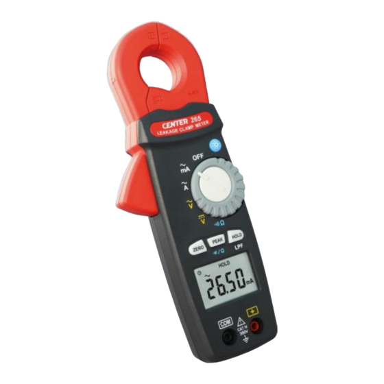
Center 265 True RMS Leakage Current Clamp Meter 4. DESCRIPTION OF THE INSTRUMENT 4-1 Description of the Display Auto power off indication Polarity indication Low battery indication AC measurement indication DC measurement indication Current measurement indication Voltage measurement indication ZERO indication... -
Page 7: Description Of Front And Rear
Clamp Meter 4-2 Description Of Front And Rear ○ Current Sensing Clamp ○ Safety protection ring ○ Backlight button ○ Clamp opening handle ○ Function select dial ○ ZERO button ○ PEAK & button ○ Data hold & LPF button ○... -
Page 8: Button Instruction
Center 265 True RMS Leakage Current Clamp Meter 5. BUTTON INSTRUCTION 5-1 HOLD & LPF Function It is possible to freeze the displayed value by pressing on the "HOLD" button. Press the "HOLD" button again to exit the Hold mode. -
Page 9: Measuring Instruction
Clamp Meter 6. MEASURING INSTRUCTION 6-1 AC A and AC mA measurement: Set the range selector switch to the desired position. The current to be measured should be within the selected measuring range. Normal measurement (see Fig.1): Press the jaw trigger to open the clampmeter jaws and close them over one conductor only. -
Page 10: Ac V Measurement
Center 265 True RMS Leakage Current Clamp Meter Fig.2 Measuring out of balance leakage current: 3-Phase 3-Wire system Single-Phase 2-Wire system 6-2 AC V Measurement: WARNING! Maximum Input Voltage is 300V AC/DC. Do not attempt to Take any voltage measurement that may exceed this maximum to avoid Electrical shock hazard and/or damage to this instrument. -
Page 11: Dc V Measurement
Clamp Meter 6-3 DC V Measurement: Switch main function selector to range. Connect the red test lead to the “ + ” terminal and black lead to the “COM”terminal. Measure voltage touching the test lead tips to the test circuit where the value of voltage is needed. -
Page 12: Resistance Measurement
Center 265 True RMS Leakage Current Clamp Meter 6-5 Resistance Measurement Switch the main function to range. Connect the red test lead to the “+”terminal and the black lead to the "COM" terminal. Connect tip of the test leads to the points where the value of the resistance is to be measured. -
Page 13: Maintenance
Keep the cable in the center of the clamp will return a more accurate test result when making current measurements. Repairs or servicing not covered in this manual should only be performed by qualified personnel.
Need help?
Do you have a question about the 265 and is the answer not in the manual?
Questions and answers