Advertisement
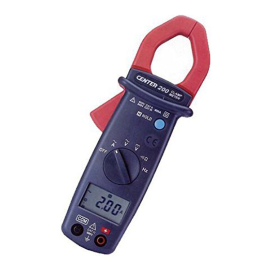
Instrument Familiarization

- Current Sensing Clamp
- Safety protection ring
- Clamp opening handle
- Function select dial
- LCD display
- COM input terminal
- Positive input terminal
- Data hold button
- Battery cabinet
Symbol Definition:

 | Low battery indication |
| AUTO | Auto range indication |
 | Manual range indication |
 | Hold Data indication |
 | Continuity function indication |
| V | Voltage measurement indication |
| A | Current measurement indication |
 | Alternative source indication |
 | Direct source indication |
 | Polarity indication |
 | Analog bar graph indication |
| MK Hz | Frequency Measurement indication |
Measuring Instruction
ACA measurement
Switch the main function selector to A  range. Open the clamp by pressing the jaw-opening handle and insert the cable to be measured into the jaw.
Close the clamp and get the reading from the LCD panel.
Note:
Before this measurement, disconnect the test lead with the meter for safety.
In some occasion that the reading is hard to read, push the HOLD button and read the result later.

ACV measurement
Switch the main function selector to V range. Connect red test lead to "+" terminal and black one to the " COM " terminal.
Measure the voltage by touch the test lead tips to the test circuit where the value of voltage is needed.
Read the result from the LCD panel.

DCV measurement
Switch the main function selector to V  range. Connect red test lead to "+" terminal and black one to the " COM " terminal.
Measure the voltage by touch the test lead tips to the test circuit where the value of voltage is needed.
Read the result from the LCD panel.

Resistance measurement
Switch the main function to  range. Connect red test lead to "+" terminal and black one to the " COM " terminal.
Connect tip of the test leads to the points where the value of the resistance is needed.
Read the result from the LCD panel.
Note:
When take resistance value from a circuit system, make sure the power is cut off and all capacitors need to be discharged.

Continuity Test
Switch the main function to range. Connect red test lead to "+" terminal and black one to the " COM " terminal.
Connect tip of the test leads to the points where the conduction condition needed.
If the resistance is under 40Ω, the beeper will sound continuously.

Frequency measurement from the terminals
Switch the main function to " Hz " range. Connect red test lead to "+" terminal and black one to the " COM " terminal.
Connect tip of the test leads to the points where the value of the resistance is needed.
Connect tip of the test leads to the points where the frequency of the voltage signal is needed.
Read the Result from the LCD panel.

Frequency measurement with the clamp
Switch the main function selector to" Hz " range.
Open the clamp by pressing the clamp-opening handle and insert the cable to be measured into the clamp.
Close the clamp and get the reading form the LCD panel.
Note:
When doing frequency measurement, user should either use the terminal signal or clamp signal but not both. If both sources are applied an error will occur.

Battery Changing

- When the battery voltage drop below proper operation range the
![]() symbol will appear on the LCD display and the battery need to changed.
symbol will appear on the LCD display and the battery need to changed. - Before changing the battery, switch the main dial to "OFF " and disconnect test leads.
Open the cover of the battery cabinet by a screwdriver.
Replace the old batteries with two UM-4 or AAA size batteries. - Close the battery cabinets cover and fasten the screw.
 symbol will appear on the LCD display and the battery need to changed.
Maintenance

Before open the battery door, disconnect both test lead and never uses the meter before the battery door is closed.

To avoid contamination or static damage, do not touch the circuit board without proper static protection.
REMARK
- If the meter is not going to be used for a long time, take out the battery and do not store the meter in high temperature or high humidity environment.
- When take current measurement, keep the cable at the center of the clamp will get more accurate test result.
- Repairs or servicing not covered in this manual should only by qualified personal.
CLEANING
Periodically wipe the case with a dry cloth and detergent.
Do not use abrasives or solvents on this instrument.
Safety Information
Do not operate the tester if the body of meter or the test lead look broken.
Check the main function dial and make sure it is at the correct position before each measurement. Do not perform resistance and continuity test on a live power system.
Do not apply voltage between the test terminals and test terminal to ground that exceed the maximum limit record in this manual.
Exercise extreme caution when measuring live system with voltage greater than 60V DC or 30V AC. Keep the fingers after the protection ring when measuring through the test lead.
Change the battery when the  symbol appears to avoid incorrect data.
Environmental Conditions:
Altitude up to 2000 meters.
Operating temperature: 0°C ~ 40°C, <80% RH, non-condensing
Storage temperature: -10°C ~ 60°C, <70% RH, battery removed
Pollution Degree: 2
Installation Categories II
Explanation of Symbols:
 Attention! Refer to operation Instructions.
 Dangerous voltage may be present at terminals.
 This instrument has double insulation.
Specification
General Specification:
Digital Display:
3 3/4 digits LCD display with maximum reading 3999
Analog Display: 42 segments fast analog bar display
Symbol and Scale range:
adjust automatically according range and input signal
Polarity:
When negative signal in apply to the tester,  will show.
Over Load:
When the signal larger than the maximum will be show 
Sample Rate:
2 times/sec for digital data
20 times/sec for analog bar
Low Power Indication:
When the battery is under the proper operation range,  will appear on the LCD display.
Power Source: UM-4 or AAA 1.5V battery x 2.
Auto Power Off:
If there is no key or dial operation for 30 minutes, the meter will power itself off to save battery consumption.
Clamp opening size: 25mm Dimension (L x W x H):
193 x 50 x 28mm, 7.60 x 1.97 x1.1 inch
Weight: 230g, 8.11OZ ( include battery)
Accessory:
Instruction Manual, Leather Case, Test lead, Battery 1.5Vx2
Battery Life: 250 hr approx. (alkaline battery)
Electrical Specification:
The accuracy specification is defined as ±(...%reading+...count )
At 23±5℃, ≦80 %RH
DCV (Autorange)
| Range | Resolution | Accuracy | Input Impedance | Overload Protection |
| 400V | 0.1V | 1%+2 | 1MΩ | 660Vrms |
| 600V | 1V |
ACV (Autorange)
| Range | Resolution | Accuracy | Input Impedance | Overload Protection |
| 50Hz~500Hz | ||||
| 400V | 0.1V | 1.5%+5 | 1MΩ | 660Vrms |
| 600V | 1V |
ACA (Autorange)
| Range | Resolution | Accuracy | Overload Protection | |
| 40A | 0.01A | 50Hz~60Hz | 60Hz~500Hz | 600Arms |
| 400A | 0.1A | 1.9%+5 | 2.5%+5 | |
Ohm ( Ω )
| Range | Resolution | Accuracy | MAX Test Voltage | Overload Protection |
| 400Ω | 0.1Ω | 1%+2 | 1.5VDC | 600Vrms |
Continuity ( )
| Range | Active Region | MAX Test Voltage | Overload Protection |
| | <40 Ohm | 1.5 VDC | 600Vrms |
Frequency (Hz) (Autorange)
| Function | Range | Resolution | Accuracy | Sensitivity | Overload Protection |
| Current Frequency | 20Hz - 4KHz | 1Hz | 0.1%+1 | 2Arms | 600Arms |
| 10KHz | 10Hz | ||||
| Voltage Frequency | 10Hz-4KHz | 1Hz | 0.1%+1 | 3Vrms | 600Vrms |
| 40KHz | 10Hz | ||||
| 400KHz | 100Hz | ||||
| 1MHz | 1KHz | 5Vrms |
CENTER TECHNOLOGY CORP.
4 / F NO. 415, Jung-Jeng Rd., 238 Shu-Lin, Taipei, Taiwan
TEL: 886-2-26763926
E-Mail: center@centertek.com
FAX: 886-2-26763925
http://www.centertek.com
Documents / Resources
References
Download manual
Here you can download full pdf version of manual, it may contain additional safety instructions, warranty information, FCC rules, etc.
Advertisement


Need help?
Do you have a question about the 200 and is the answer not in the manual?
Questions and answers