Advertisement
Quick Links
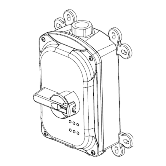
DISCONNECT SWITCH (HBLDS30 Series)
GENERAL INFORMATION:
• This Disconnect Switch provides ON-OFF control of a directly connected load.
• These devices are suitable for indoor and outdoor locations where watertight, corro-
sion resistant, or dust tight protection is required.
• This MANUAL MOTOR CONTROLLER is additionally listed within its horsepower
and voltage ratings as SUITABLE FOR MOTOR DISCONNECT, and provides ON-
OFF switched CONTROL and ISOLATION of connected loads from its power sup-
ply.
• NOTICE: For installation only by a qualified electrician in accordance with the Na-
tional Electrical Code® or the Canadian Electrical Code, local codes, and the in-
structions on the following pages.
• CAUTION: RISK OF ELECTRIC SHOCK. MORE THAN ONE SUPPLY DISCON-
NECT MAY BE REQUIRED TO DE-ENERGIZE THIS EQUIPMENT BEFORE SER-
VICING. DISCONNECT ALL POWER SUPPLIES TO ENCLOSURE BEFORE EX-
POSING INTERIOR.
• NOTICE: Separate overcurrent protection must be provided upstream in accordance with the National Electrical
code® Article 240 or Canadian Electrical Code, Section 14, as appropriate.
• FOR USE WITH COPPER CONDUCTORS ONLY.
• DO NOT tin conductors.
• Conductors shall be sized in accordance with the 60 °C column of Table 310.16 of the National Electrical Code or
Table 2 of the Canadian Electrical Code. Conductor insulation shall be rated 90 °C or higher.
• Suitable for use on a circuit capable of delivering not more than 10,000 rms symmetrical amperes, 600 VAC maxi-
mum.
• Suitable for use on a circuit capable of delivering not more than 65,000 rms symmetrical amperes, 600 VAC maxi-
mum when protected by Class J fuses rated 30 amperes maximum.
• This Disconnect Switch includes a lockout provision: ON-OFF control knob (in the OFF position) accepts up to a
5/16 inch (8mm) diameter shackle of a suitable padlock Lockout device to isolate energy from the connected equip-
ment as a method of compliance to OSHA Lockout/Tagout Regulation 29 CFR Part 1910.147. This feature, howev-
er, does NOT isolate the power supplied to the enclosure during internal servicing of the enclosure.
RATINGS: HBLDS30 Series
TABLE 1
30 Amp
600 VAC
1 HP
120 VAC 1Ø
3 HP
200-240 VAC 1Ø
5 HP
480 VAC 1Ø
7.5 HP
200-240 VAC 3Ø
15 HP
480 VAC 3Ø
15 HP
600 VAC 3Ø
Wiring Device-Kellems
Hubbell Incorporated (Delaware)
1-800-288-6000
Shelton, CT 06484
www.hubbell-wiring.com
PD3049 (Page 1)
HUBBELL 30 AMP CIRCUIT-LOCK
Installation and Operation Instructions
NOTICE: READ BEFORE INSTALLING AND USING THIS DEVICE.
TABLE 2
Switch
Ground
Neutral
Auxilary Contact
800H Selector Switch
800FP-SL32 Selector
Switch
04/24
CONDUCTOR
WIRE GA.
STRIP LENGTH
#8 to #14AWG
1/2 inch (13 mm)
#6 to #16 AWG
1/2 inch (13 mm)
#8 to #22 AWG
1/2 inch (13 mm)
#14 to #18 AWG
1/2 inch (13 mm)
#8 to #10AWG
1/2 inch (13 mm)
#8 to #12AWG
1/2 inch (13 mm)
Assembled in U.S.A.
Patent Pending
SCREW TORQUE
50 lb-in (5.7 N-m)
35.4 lb-in. (3.9 N-m)
35.4 lb-in. (3.9 N-m)
9 lb-in. (1.0 N-m)
6-8 lb-in (0.7-0.9 N-m)
6-8 lb-in (0.7-0.9 N-m)
Advertisement

Related Manuals for Hubbell CIRCUIT-LOCK HBLDS30 Series


Summary of Contents for Hubbell CIRCUIT-LOCK HBLDS30 Series
- Page 1 HUBBELL 30 AMP CIRCUIT-LOCK DISCONNECT SWITCH (HBLDS30 Series) Installation and Operation Instructions NOTICE: READ BEFORE INSTALLING AND USING THIS DEVICE. GENERAL INFORMATION: Assembled in U.S.A. • This Disconnect Switch provides ON-OFF control of a directly connected load. Patent Pending • These devices are suitable for indoor and outdoor locations where watertight, corro- sion resistant, or dust tight protection is required.
-
Page 2: Installation
Note: When connecting the upper left side hole location to a metallic conduit, a grounding (bonding) plate should be installed to ensure continuity of wiring system grounding. See Hubbell PD 3077. 1. Top feed is shown in Fig. M-3. Bottom feed is shown in Figs. M-4 and M-5. - Page 3 HUBBELL 30 AMP CIRCUIT-LOCK DISCONNECT SWITCH (HBLDS30 Series) C. DUAL CONDUIT ENTRY AND BACK FEED: See Figs. M-4 and M-5. Remove frame retention screws and remove frame. Drill or punch a 1.109 inch diameter (3/4” trade size) hole at the desired conduit entrance location. Use drill spots to accurately locate hole.
- Page 4 HUBBELL 30 AMP CIRCUIT-LOCK DISCONNECT SWITCH (HBLDS30 Series) D. WIRING INSTRUCTIONS 1. Caution: Ensure the connected device rating does not exceed the rating of this device. See General infor- mation regarding overcurrent protection. 2. Select the correct wiring diagram and wire the switch as shown.
- Page 5 HUBBELL 30 AMP CIRCUIT-LOCK DISCONNECT SWITCH (HBLDS30 Series) CLEANING PROCEDURES: • CAUTION: Use only chemicals and cleaning solutions that are safe for use with plastics and rubber gaskets. • CAUTION: Risk of electric shock. Do not clean this product while undergoing electrical maintenance or service 1.
Need help?
Do you have a question about the CIRCUIT-LOCK HBLDS30 Series and is the answer not in the manual?
Questions and answers