
Related Manuals for Hubbell USCO AVR


Summary of Contents for Hubbell USCO AVR
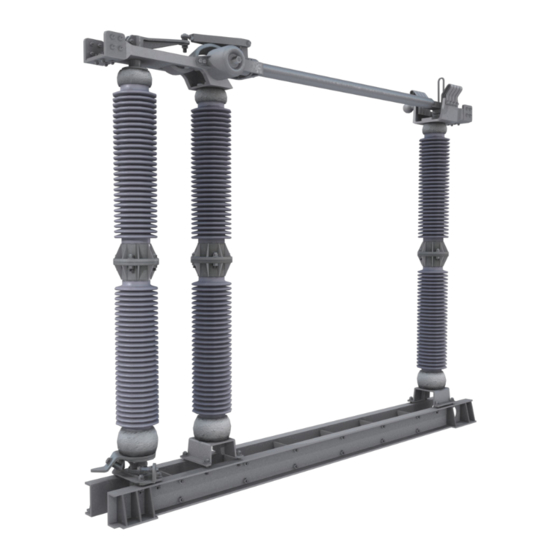
- Page 1 USCO™ Types AVR & AVRV Group Operated Aluminum, Outdoor, Vertical Break Air Switch 8.3 - 245 kV, 1200 - 3200A...
-
Page 2: Table Of Contents
Final Checklist ....................................8 Use of Leveling Studs ................................. 8 Installation Troubleshooting ..............................9 Installation Considerations ............................... 11 Operation Guide ................................... 12 Maintenance Guide ..................................14 Switch ldentification ................................... 15 Renewal Parts and Factory Service............................16 hubbell power systems... -
Page 3: Receiving Inspection
If the switch crate is damaged, remove the tie wires on each phase unit and operate the switch a few times, making sure the switch is not affected. If damage is found or suspected, file a claim immediately with the freight company and notify your local Hubbell representative. Handling and Storage Take a reasonable amount of care when handling and storing air break switches. - Page 4 Twist Pin Upper Drive Arm Jaw Contact Terminal Pad Blade Stop Closed Stop Twist Clamp Slot For Side-Side Adjustment Lower Operating Arm Leveling Studs Closed Stop Bearing Peg Bolts (When Furnished) FIGURE 2 - TYPICAL AVRV PHASE UNIT hubbell power systems...
-
Page 5: Mounting The Switch And Controls
Connect the reach rod as shown on the control drawing. If necessary, slide the adjustable arm up to the proper elevation and rotate it to the correct position (as shown on the control drawing), and pierce the set screws to hold the adjustable arm hubbell.com hubbell.com... - Page 6 systems...
-
Page 7: Switch And Control Adjustment
Check the arcing horns, if furnished, ensuring that continuous contact is made during the opening and closing of the switch. If not, slightly bend the arcing horns to make contact. Jaw Contact Alignment Acceptable Contact 1/4" Maximum Range FIGURE 4 - JAW CONTACT TOLERANCES hubbell.com... -
Page 8: Terminal Connections
2. Turn nut B on each stud counterclockwise until the adjustment is made. Note that tall insulators will only require a slight movement at the leveling studs to move the insulator several inches. Tighten nut A (and the peg bolts if equipped.) hubbell power systems... -
Page 9: Installation Troubleshooting
Contact your local Hubbell representative for additional information or troubleshooting assistance. Problem: In the closed position, the operating arms are against the closed stops, but in the open position, the switch phases are not fully open and the operating arms are not against the open stops. - Page 10 Rotate the operating fork 1/2 turn to shorten the linkage. Replace the twist pin and check operation. If necessary, shorten the linkage some more. When adjustment is complete, remember to replace the cotter pin and tighten the locknut on the ball joint. hubbell power systems...
-
Page 11: Installation Considerations
5.11 Inspection: Prior to being placed in service, the equipment should be carefully inspected and adjusted in accordance with the applicable drawings. The following suggestions are strongly advised prior to energization: hubbell.com... -
Page 12: Operation Guide
The control circuits and mechanism should be checked in this manner unless the overall adjustments are affected hubbell power systems... - Page 13 6.3 Load Interrupter Switches: Interrupter switches have specific capabilities for switching one or more of the following circuit types: 0.8 minimum lagging power factor load, parallel or loop load, transformer magnetizing, line charging, cable charging, and capacitor bank. Follow the manufacturer's instructions when operating interrupter switches. hubbell.com...
-
Page 14: Maintenance Guide
Do not grease the contacts. If lubrication is desired, spray the contacts with a dry graphite aerosol. Inspect arcing horns for signs of excessive arc damage and replace if necessary hubbell power systems... -
Page 15: Switch Ldentification
Section 7.1. Switch Identification When contacting the factory, refer to the Sales Order (SO) and line item number shown on the nameplate. All pertinent information on the switch is filed under this number. hubbell.com... -
Page 16: Renewal Parts And Factory Service
WARNING - De-energize and properly ground any applicable and adjacent equipment before performing any installation or maintenance. Work should only be undertaken by qualified personnel. ©2023 Hubbell Power Systems. All rights reserved. Hubbell and the Hubbell logo are registered trademarks or trademarks of Hubbell Incorporated. A proud member of the Hubbell family.
Need help?
Do you have a question about the USCO AVR and is the answer not in the manual?
Questions and answers