Advertisement
Table of Contents
Installation, OPERATION and MAINTENANCE
CHANCE TYPE M3 STATION SWITCH
GENERAL
WARNING
!
Read and understand these instructions before
installation or operation of this equipment. Competent
personnel who understand proper safety procedures
must select, install, and service this equipment. This
instruction guide is written for such personnel. This
guide is not a substitute for adequate training and
experience in safety procedures for this type of
equipment.
The A. B. Chance Type M3 disconnect switch is a
single-phase hookstick operated switch. It is for
manual switching of de-energized or parallel circuits
of overhead lines on an electrical distribution system.
The M3 switch has no current making or breaking
capacity. Design variations allow for applications as
an electrical distribution switch or as an electrical
station switch. A number of options (connectors,
captive hardware, by-pass studs, etc.) are available
to better fit the user's needs.
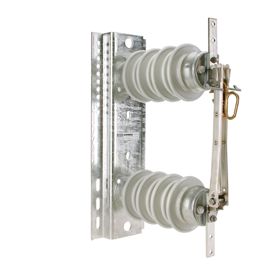
The station style M3 disconnect switch is made for
mounting in an inverted (Figure 1) or vertical position
(Figure 2).
Select a properly rated M3 switch for each installation
with consideration to continuous current, BIL, and
rated voltage. Should there be any concern on the use
of this M3 switch as rated, consult your supervisor
before installation.
Inspect the switch for damage or missing parts. If
damage from rough handling is evident, immediately
file a claim with the transportation company. Contact
the nearest Chance sales office for replacement parts.
These instructions do not claim to cover all details or variations in equipment, nor to provide for all possible conditions to be met
with concerning installation, operation, or maintenance of this equipment. If further information is desired or if particular
problems are encountered which are not sufficiently covered in this guide, contact A. B. Chance Company.
NOTE:
Because Hubbell has a policy of continuous product improvement, we reserve the right to change design and specifications without notice.
© Copyright 1996 Hubbell / Chance, 210 N. Allen, Centralia, MO 65240
®
POWER SYSTEMS, INC.
INSTRUCTIONS
FOR
BY PASS
STUD
(OPTIONAL)
CONNECTOR
(OPTIONAL)
Figure 1 — Inverted-Underhung
Printed in USA
®
BASE
INSULATOR
BLADE STOP PIN
OPEN LATCH
(OPTIONAL)
PULL RING
LOADBREAK HOOKS
Figure 2 — Vertical Mount
Part No. P807-0199
Rev. C 6/96
Advertisement
Table of Contents

Related Manuals for Hubbell M3


Summary of Contents for Hubbell M3
- Page 1 A. B. Chance Company. NOTE: Because Hubbell has a policy of continuous product improvement, we reserve the right to change design and specifications without notice. © Copyright 1996 Hubbell / Chance, 210 N. Allen, Centralia, MO 65240 Printed in USA ®...
- Page 2 INSTALLATION The M3 switch is supplied with a blade stop pin. Before raising switch for mounting, place this pin in the proper hole to obtain either a 90° or 160° (Figure 3) blade opening. Some switches may be supplied with an open blade latch. The stop pin must be in the 160°...
- Page 3 Figure 5 The M3 switch is properly closed when the blade hook is fully engaged with the latch portion of the blade stop as shown in Figure 6.
- Page 4 C37.35 “IEEE Guide for the Application, Installation, Operation, and Maintenance of High Voltage Air Disconnecting and Load Interrupter Switches.” ® ® POWER SYSTEMS, INC. © Copyright 1996 Hubbell / Chance, 210 N. Allen, Centralia, MO 65240 Printed in USA Part No. P807-0199 Rev. C 6/96...
Need help?
Do you have a question about the M3 and is the answer not in the manual?
Questions and answers