
Related Manuals for Hubbell USCO AGCH5


Summary of Contents for Hubbell USCO AGCH5
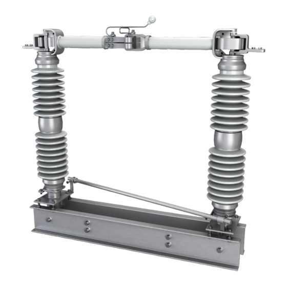
- Page 1 USCO™ Types AGCH5 & GCH4 Group Operated, Outdoor, Center Break Air Switch 8.3 - 362 kV, 1200 - 6000 A...
-
Page 2: Table Of Contents
Use of Leveling Studs ................................. 8 Changing Switch Opening Direction ........................... 9 Installation Troubleshooting ..............................10 Installation Considerations ..............................11 Operation Guide ................................... 12 Maintenance Guide ..................................14 Switch ldentification ................................... 15 Renewal Parts and Factory Service............................16 hubbell power systems... -
Page 3: Receiving Inspection
If the switch crate is damaged, remove the tie wires on each phase unit and operate the switch a few times, making sure the switch is not affected. If damage is found or suspected, file a claim immediately with the freight company and notify your local Hubbell representative. Handling and Storage Take a reasonable amount of care when handling and storing air break switches. - Page 4 "HTJC" compound or equivalent Arcing Horns Terminal Pads Hinge Blade Supports Female Blade Male Blade Insulator Cap Bolts Innerpole Linkage Switch Bearings Operating Arm Leveling Studs Stop Peg Bolts Switch Base FIGURE 1 - TYPICAL PHASE UNIT hubbell power systems...
-
Page 5: Mounting The Switch And Controls
Connect the reach rod as shown on the control drawing. If necessary, slide the adjustable arm up to the proper elevation and rotate it to the correct position (as shown on the control drawing), and pierce the set screws to hold the adjustable arm hubbell.com hubbell.com... - Page 6 systems...
-
Page 7: Switch And Control Adjustment
(if adjustment is necessary use the leveling studs, or shims under the live parts): Max. Adjustment ℄ From Properly Aligned Contact Male Contact to End of Contact Back-Up Male Contact Contact Backup FIGURE 3 - JAW CONTACT TOLERANCES hubbell.com... -
Page 8: Terminal Connections
2. Turn nut B on each stud counterclockwise until the adjustment is made. Note that tall insulators will only require a slight movement at the leveling studs to move the insulator several inches. Tighten nut A (and the peg bolts if equipped) hubbell power systems... -
Page 9: Changing Switch Opening Direction
Operate the switch several times to verify that the contacts are properly aligned and the switch phase travels fully open and closed. Male Female Right Hand Switch Left Hand Switch Female Male Drive End FIGURE 6 - SWITCH OPENING DIRECTIONS hubbell.com... -
Page 10: Installation Troubleshooting
Contact your local Hubbell representative for additional information or troubleshooting assistance. Problem: In the closed position, the operating arms are against the closed stops, but in the open position, the switch phases are not fully open and the operating arms are not against the open stops. -
Page 11: Installation Considerations
See 5.9 for adjustment considerations. 5.4 Rigidity: All switch bases and associated stationary parts should be rigidly bolted in place. 5.5 Line Conductors: Conductors should not subject the switching equipment to undue strains which could cause contact misalignment. hubbell.com... -
Page 12: Operation Guide
Guide for the Operation of High Voltage Disconnecting Switches IEEE 37.30.1 Operation Air Switches: High voltage disconnecting switches and ground switches are given no interrupting rating. If an interrupter is installed, the switch's break capability will be dependent upon the interrupter's ratings. hubbell power systems... - Page 13 6.3 Load Interrupter Switches: Switches with interrupters installed have specific capabilities for switching one or more of the following circuit types: 0.8 minimum lagging power factor load, parallel or loop load, transformer magnetizing, line charging, cable charging, and capacitor bank. Follow the manufacturer's instructions when operating interrupter switches. hubbell.com...
-
Page 14: Maintenance Guide
(remove) or per factory recommendation. (Do not grease the contacts. If additional lubrication is desired, spray the contacts with a dry graphite aerosol.) Inspect arcing horns for signs of excessive arc damage and replace if necessary hubbell power systems... -
Page 15: Switch Ldentification
Section 7.1. Switch Identification When contacting the factory, refer to the Sales Order (SO) and line item shown on the nameplate. All pertinent information on the switch is filed under this number. hubbell.com... -
Page 16: Renewal Parts And Factory Service
WARNING - De-energize and properly ground any applicable and adjacent equipment before performing any installation or maintenance. Work should only be undertaken by qualified personnel. ©2023 Hubbell Power Systems. All rights reserved. Hubbell and the Hubbell logo are registered trademarks or trademarks of Hubbell Incorporated. A proud member of the Hubbell family.
Need help?
Do you have a question about the USCO AGCH5 and is the answer not in the manual?
Questions and answers