
Related Manuals for Stratasys Dimension 1200es


Summary of Contents for Stratasys Dimension 1200es
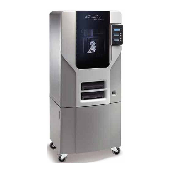
- Page 1 | c-support@stratasys.com Dimension 1200es/1200 ® 3D Printer Service Manual Part No. 209008-0001, Rev F April 2014...
- Page 2 This document is protected by copyright. All rights reserved. Its use, disclosure, and possession are restricted by copyright. No part of this document may be photocopied, reproduced or translated into another language without the prior written consent of Stratasys, Inc. Printed in the USA.
-
Page 3: About This Guide
About This Guide This service guide is designed to help you easily find the information you need to successfully service Dimension BST and SST systems. This guide is arranged in chapters with tabs for easy reference. When viewing the electronic PDF version, you can easily hyperlink to specific headings or chapters using the following methods: •... -
Page 5: Table Of Contents
Table of Contents Safety _______________________________________________________ 1-1 Hazard Classifications _______________________________________________________________ 1-1 Product Safety Symbols ______________________________________________________________ 1-1 Product Information Symbol__________________________________________________________ 1-1 Safety Devices ______________________________________________________________________ 1-1 System Overview ____________________________________________ 2-1 Dimension 1200/1200es Specifications________________________________________________ 2-2 Physical specifications ______________________________________________________________ 2-2 Facility specifications________________________________________________________________ 2-2 Workstation specifications ___________________________________________________________ 2-3 Environmental specifications_________________________________________________________ 2-3 What Happens When... - Page 6 Service Procedures __________________________________________ 4-1 Maintenance Preparation____________________________________________________________ 4-3 Pre-Maintenance Procedures ________________________________________________________ 4-3 Required Tools list ___________________________________________________________________ 4-4 Distributor/Reseller supplied Tools _________________________________________________ 4-4 Supplied by Stratasys ____________________________________________________________ 4-4 Exterior Components ________________________________________________________________ 4-5 Rear Panel ______________________________________________________________________ 4-5 Side Panels ______________________________________________________________________ 4-6 User Interface Panel _____________________________________________________________ 4-7...
- Page 7 120 VDC Power Supply (SST only) ________________________________________________ 4-45 5/12 VDC Power Supply _________________________________________________________ 4-48 Line Filter Board_________________________________________________________________ 4-51 AC Input _______________________________________________________________________ 4-54 Circuit Breaker__________________________________________________________________ 4-57 Gen 3 Electrical Components _______________________________________________________ 4-60 Power Distribution Board (PDB) __________________________________________________ 4-60 Controller Board ________________________________________________________________ 4-69 Single Board Computer (SBC) ___________________________________________________ 4-74 Hard Drive______________________________________________________________________ 4-81 Electronics Bay Cooling Fan _____________________________________________________ 4-87...
- Page 8 Chamber Thermocouple _______________________________________________________ 4-223 Chamber Heater ______________________________________________________________ 4-225 Chamber Fans ________________________________________________________________ 4-229 Z Sensors ______________________________________________________________________ 4-233 Purge Bucket Light _____________________________________________________________ 4-235 Z Motor & Belt _________________________________________________________________ 4-237 Z Stage Assembly ______________________________________________________________ 4-240 Receiver Components ____________________________________________________________ 4-250 Receiver Back Panel Assembly _________________________________________________ 4-250 Misc.
- Page 9 Major Codes ___________________________________________________________________ 6-16 Major Codes with Minor Codes __________________________________________________ 6-17 Non-Code Errors ___________________________________________________________________ 6-31 Part Quality Troubleshooting ________________________________________________________ 6-44 Brown streaks (burn marks) ______________________________________________________ 6-45 Loss of Extrusion (LOE) ___________________________________________________________ 6-46 Model embedded in to support _________________________________________________ 6-47 Moisture in material _____________________________________________________________ 6-48 Open seams ___________________________________________________________________ 6-49 Part curling _____________________________________________________________________ 6-50 Part fell over____________________________________________________________________ 6-51...
- Page 10 XY Table Installation Checklist _______________________________________________________ 9-5 Pre-Installation Checklist_____________________________________________________________ 9-6 System Information ______________________________________________________________ 9-6 System Installation Checklist _________________________________________________________ 9-7 Training Checklist ___________________________________________________________________ 9-8 Required Tool List ___________________________________________________________________ 9-10 Distributor/Reseller supplied _____________________________________________________ 9-10 Supplied by Stratasys (From attending training only) ______________________________ 9-10 Index_________________________________________________________ I-1...
-
Page 11: Safety
Safety Dimension 1200es/1200 are designed to be safe and reliable rapid prototyping systems. However, as an installer and service engineer for this equipment, it will be required that you access areas of the printer that are potentially dangerous. This chapter includes the hazard classifications that are listed throughout this guide. -
Page 13: System Overview
System Overview In this chapter you will learn about the main components of the system. The contents and page numbers of this chapter are as follows: Dimension 1200/1200es Specifications _______________________________________________ 2-2 Physical specifications ______________________________________________________________ 2-2 Facility specifications _______________________________________________________________ 2-2 Workstation specifications __________________________________________________________ 2-3 Environmental specifications ________________________________________________________ 2-3 What Happens When...______________________________________________________________ 2-3 Powering Up_____________________________________________________________________ 2-3... -
Page 14: Dimension 1200/1200Es Specifications
Dimension 1200/1200es Specifications Build Size Parts can be built up to 254 x 254 x 305 mm (10 x 10 x 12 in.) Material 1200 ABS- White, Black, Steel Grey, Red, Blue, Green, Yellow. 1200es ABS+ - Ivory, White, Black, Dark Grey, Red, Blue, Olive Green, Nectarine, Fluorescent Yellow. -
Page 15: Workstation Specifications
Workstation specifications Operating System Microsoft Windows XP, Microsoft Windows Vista or Microsoft Windows 7 Processor Minimum: 2.4 GHz Faster processors will shorten job processing times Minimum: 1GB (2GB for Windows Vista or Windows 7) Recommended: 2GB (3GB for Windows Vista or Windows 7) Hard Disk Installation: 90MB Monitor graphics... -
Page 16: Powering Off
Powering Off When the PDS (Power Down Switch) is turned off, the unit begins a controlled shut down. The active software processes are suspended, eliminating any disk I/O. The power to the liquefier and chamber is turned off. The Controller board monitors the temperature of the liquefier and chamber. -
Page 17: A System Error Occurs
A System Error Occurs Should an error occur during normal operation, the SBC will display SYSTEM ERROR followed by an error code such as code 14, 4. A code 14 is an error reported by the Controller board and the 4 indicates a bad or missing modeling base (foam or substrate). For a complete list of error codes, see Troubleshooting on page 6-1. -
Page 18: Gen 2 Electronics
Gen 2 Electronics Electronics Overview Figure 2-1: Gen 2 electronics block diagram... -
Page 19: Single Board Computer
Single Board Computer The single board computer (SBC) is the main processor in the system. It is a complete “PC compatible computer” on a single board. See Figure 2-2. The TCP/IP network interface connects directly to the RJ-45 connector on the SBC. The network interface supports both 10baseT and 100baseT operation. - Page 20 Figure 2-3: Old Ampro SBC detail Manufacturer name AMPRO To Power Down Switch and LCD To hard drive (ribbon cable) To LCD (ribbon cable) +5 and +12 VDC input RJ-45 Network connection Ampro SBC Figure 2-4: Nova 600 SBC detail Manufacturer name To hard drive (ribbon cable)
-
Page 21: Controller Board
Controller Board Overview The controller board in BST/SST provides all of the low level hardware control and sensing for the system. The software runs on the controller cpu and is flash resident (rather than on the HDD as with the SBC). Voltage Generation •... -
Page 22: Liquefier Temperature Control
Liquefier Temperature Control The liquefier T/C connects to the controller board through the power distribution board. The T/ C generates a variable low level current that depends on the temperature of the T/C. This analog signal from the T/C is amplified by the head board. It is then sent down the umbilical cable to the PDB, and then to the controller board. - Page 23 Actuators, Switches & Optical Sensors The input and output signals are passed through the PDB and then processed by the controller board. The non-motor actuators on a BST/SST system are 24 volt solenoids. The 24 volt power is supplied by the PDB which in turn is controlled by the controller board. The following is a list of actuators: •...
-
Page 24: Reset Button
Controller Board Layout Figure 2-6 below shows the layout of the controller board connectors with labels indicating where each of the functions described previously are connected. In addition to those functions, the figure shows a reset button, a set of dip switches, and the LEDs (D1-D3 and D6-D13). Figure 2-6: Controller board detail DIP switches SW2 SW5 SW6... - Page 25 Number (in black) Description Setting Default PMD pilot baud rate 57600 1-2 off, 3 on Pilot parity bits None Pilot stop bits Pilot protocol Point to point Unused Unused Number (in white) Description Default 16-24 Unused Number (in white) Description Default 8-15 Unused...
- Page 26 LEDs There are 11 LEDs located on the controller board. A grouping of three (D1-D3) are located on the lower left side. The other group of eight (D6-D13) are located on the upper right side. D1-D3 are lit when their associated voltage, as shown in table below, is present. The 3.3 VDC supply is generated on the controller board, +5 and +12 VDC come from the PDB.
-
Page 27: Power Distribution Board (Pdb)
Power Distribution Board (PDB) Figure 2-7: Power distribution board detail J16 - To LCD display (ribbon) J21 - Not used J13 - Chamber thermocouple connector J24 - To external UPS dry contact (768 Only) J14 - To controller (ribbon cable) J7 - To receiver J9 - Head umbilical II (X motor, filament motors,... -
Page 28: Chamber Temperature Control
AC line voltage comes into the PDB (Figure 2-7.) The voltage is routed through the solid state relay to an auto switching circuit. The circuit is used to supply the chamber heater voltage: 240 VAC in series, or 120 VAC in parallel. The solid state relay is controlled by the controller board, and turns the heater on/off to regulate the chamber temperature. -
Page 29: Test Points
Test Points Test points, located on the PDB board, are very useful for troubleshooting the system. The test points are listed below with a brief description. System Component Test Point Description TP26 Power fail signal from external UPS +5V REF Head T/C service reference Door Switch TP12... - Page 30 System Component Test Point Description Z Foam TP27 Z substrate sensor (5 VDC) +5 VDC TP34 +5 VDC +12 VDC TP33 +12 VDC +12 VDC SW TP32 +12 VDC switched (off when power enable is off, when powering up, and during download) +24 VDC TP31 +24 VDC...
-
Page 31: Gen 3 Electronics
Gen 3 Electronics Electronics Overview Figure 2-8: Gen 3 electronics block diagram Dimension 1200/1200es Service Manual 2-19... -
Page 32: Controller Board
Controller Board Overview The controller board in BST/SST provides all of the low level hardware control and sensing for the system. The software runs on the controller cpu and is flash resident (rather than on the HDD as with the SBC). Voltage Generation •... -
Page 33: Actuators, Switches & Optical Sensors
signal from the T/C is amplified by the head board (1200) or TC Amp Board (1200es). It is then sent down the umbilical cable to the PDB, and then to the controller board. An A to D converter in the ColdFire chip converts the analog signal to digital. In order to improve temperature resolution, this signal is biased. -
Page 34: Controller Board Layout
supplied by the PDB which in turn is controlled by the controller board. The following is a list of actuators: • Door solenoid – locks the door to the modeling chamber. • Cartridge latches (2) – holds cartridges in the receiver unit. •... - Page 35 Figure 2-10: Controller board connection detail Reset Button Located on the lower right side of the board, the reset button will do a hard reset of the controller board. Before continuing with normal operation after resetting the board, system power must be cycled.
- Page 36 Number (in white) Description Default Run built-in self test (BIST) Load Firmware (turn on when using SNDBIN.EXE) Disable door latching Unused Don’t reset controller when in command is issued Disable WatchDog timer Enable use of dc commands Unused Memory There are three types of memory contained on the controller board. •...
-
Page 37: Single Board Computer
Single Board Computer The single board computer (SBC) is the main processor in the system. It is a complete “PC compatible computer” on a single board. See Figure 2-11. The TCP/IP network interface connects directly to the RJ-45 connector on the SBC. The network interface supports both 10baseT and 100baseT operation. -
Page 38: Power Distribution Board (Pdb)
Power Distribution Board (PDB) Figure 2-12: Power Distribution Board detail AC power in To power switch and main thermal cutoff fuse To chamber heaters (AC) 24VDC in Mid unit harness 2 5/12 VDC in Receiver cable To controller - ribbon cable Head umbilical 2 J10 Head umbilical I J11 Head heater... - Page 39 There are two fuses on the power distribution board. See Figure 2-12. • Fuse F1 fuses the AC input to the +120 VDC supply. • Fuse F2 fuses the +120 VDC output. Chamber Temperature Control The chamber thermocouple (T/C) connects directly to the PDB and the signal is sent to the controller board.
- Page 40 System Component Test Point Description Model Thermocouple TP22 Voltage corresponds to model temperature (10 mV=° C) CH/HD Thermostat DL31 TP25 Chamber and head thermostat (snap switches) (+5 VDC if both switches closed) Normal = tp25 lo, tp42 hi ch thermostat fault=tp25 lo, tp42 lo. Head Thermostat DL31 TP42...
- Page 41 System Component LED Description +12 V DL19 +12 VDC present +12 V SW DL22 +12 VDC switched (power enabled) +24 V DL20 +24 VDC present +24 V SW DL21 +24 VDC switched (power enabled) +120 VDC DL18 +120 VDC will blink if voltage is above +50 VDC AC On/Off DL15 Drive signal to the power down relay...
-
Page 42: Head Board
Head Board Figure 2-15: Head board layout Rear view Front view J304 Z Sensor J302 Head Motor Power J303 Head Motor Ribbon Cable J301 Umbilical Cable J102 Support Heater U303 X Home Sensor J305 Toggle Sensor Support 120VDC LED (120 VDC present if on) Model 120VDC LED (120 VDC present if on) U304 X EOT Sensor... -
Page 43: Software
Software In this chapter you will learn about the software that is used in the system. The contents and page numbers of this chapter are as follows: System Software Download Procedure _______________________________________________ 3-2 Software Architecture _______________________________________________________________ 3-3 Operating System________________________________________________________________ 3-3 Display Driver ____________________________________________________________________ 3-3 Comm Server ____________________________________________________________________ 3-4 System Manager_________________________________________________________________ 3-4... -
Page 44: System Software Download Procedure
System Software Download Procedure Required Tools • “Dimension” system software and CatalystEX CD • Crossover cable or network connection • Notebook computer or workstation with Windows 2000, XP Pro, Vista or Windows 7. Caution: Do not open the printer door or interrupt power to the printer during the upgrade. -
Page 45: Software Architecture
Software Architecture Figure 3-16. shows the major software components that control the system. The software that runs on the Controller Board is EPROM based. The software that runs on the single board computer is stored on the HDD and loaded during power up. Like all PC compatible computers, the SBC runs a brief self-test on power up and then loads the operating system followed by the system’s application components. -
Page 46: Comm Server
Comm Server The comm server software on the system is the other half of the download software that is part of the CatalystEX workstation software. Parts to be built (.cmb files) are received by the comm server and saved on the data partition of the HDD. Queue management of the parts to be built is also part of the comm server. -
Page 47: Datastatex
DataStatEX Overview To inform resellers, distributors and customer support of DataStatEX’s release and its uses. DataStatEX is a “condensed” version of MaracaEX. It was developed to: • Aid in troubleshooting system problems by allowing the customer to view and report specific system information. - Page 48 Select the “connect to modeler” (two blue arrows) button to establish communications to the system. Information is now shown in the State, Internal State, and Home State windows of DataStatEX. From this point the customer can open any of the button options.
-
Page 49: Catalystex Help
CatalystEX Help CatalystEX Overview CatalystEX is an intuitive, user-friendly application designed to interface with Dimension 3D printers. It allows you to quickly and easily open a 3D drawing of a part, prepare the drawing for print, and send the print command to create the part. CatalystEX provides 'Help' information in two ways - through a Conventional Help file and through a Dynamic Help system. -
Page 50: Maracaex Help
MaracaEX Help Overview MaracaEX is a program used for machine configuration and troubleshooting. It is intended for use by trained service personnel only. Caution: It is possible, using this program, to damage the controller software and make the machine non-functional. Using MaracaEX you can select a modeler to work with, modify machine-specific configuration parameters, download new calibration file data, download new test parts, and test the machine's operation. -
Page 51: Modeler Setup
Modeler Setup In order to use MaracaEX on a network modeler, you must first create a modeler definition. You can create modeler definitions by clicking the + button in the main window. A modeler definition is made complete by specifying the following: •... - Page 52 Versions Product Version The current version number for the complete software release. Build Version The build number for current SBC software. Firmware Version The current version for the 186/Controller software. PLD Version The current version of the programmable logic devices on the 186 or Controller boards. Product serial The serial number of the complete system.
-
Page 53: Materials
P400R - is a standard release material. P400SR - is a standard soluble release material. Manufacturing Lot This is a lot code used by Stratasys to control the manufacturing process. Manufacturing Date This is the date that the cartridge was manufactured. -
Page 54: Part Calibration
Part Calibration Left Measured on left side of modeling base, front to back. Right Measured on right side of modeling base, front to back. Front Measured on front side of modeling base, left to right. Back Measured on back side of modeling base, left to right. Left Front Measured from front left corner to rear right corner. -
Page 55: Get Calibration
Get Calibration The Get Calibration button allows a single calibration file to be retrieved from any machine with a build number greater than or equal to 1132. This calibration file will also be on the system calibration floppy disk/CD that ships in the electronics pan for systems with a build number greater than or equal to 1132. -
Page 56: Help
Help Click the question mark to display the Help files. 3-14... -
Page 57: Service Procedures
Service Procedures This chapter describes removal and replacement procedures for Dimension 1200 and 1200es printers. Maintenance Preparation ___________________________________________________________ 4-3 Pre-Maintenance Procedures _______________________________________________________ 4-3 Required Tools list___________________________________________________________________ 4-4 Distributor/Reseller supplied Tools _________________________________________________ 4-4 Supplied by Stratasys_____________________________________________________________ 4-4 Exterior Components _______________________________________________________________ 4-5 Rear Panel ______________________________________________________________________ 4-5 Side Panels ______________________________________________________________________ 4-6 User Interface Panel______________________________________________________________ 4-7... - Page 58 Head Components _______________________________________________________________ 4-108 1200 Toggle Plate Assembly ____________________________________________________ 4-108 1200es Toggle Plate Assembly __________________________________________________ 4-116 Head Alignment Procedure ____________________________________________________ 4-123 Head Toggle Bar_______________________________________________________________ 4-139 Head Toggle Sensor ___________________________________________________________ 4-140 1200 Head Board ______________________________________________________________ 4-141 1200es Head Board ____________________________________________________________ 4-143 1200es TC Amp Board__________________________________________________________ 4-145 Head Motor ___________________________________________________________________ 4-146 Z Level Assembly (Z Foam Sensor) _______________________________________________ 4-149...
-
Page 59: Maintenance Preparation
Maintenance Preparation Should you have any questions about Dimension 1200 /1200es replacement procedures, contact Stratasys Customer Support at 1-800-801-6491 for further information or assistance. Read these warnings before performing any service on this system! Warning: Make sure the power is disconnected when performing any of the disassembly or assembly instructions in this chapter. -
Page 60: Required Tools List
Serial data cable (for issuing Tera Term commands). Serial to USB adapter, recommended IOGEAR GUC232A (for issuing Tera Term commands). Supplied by Stratasys Belt tension gauge (for adjusting XY table drive belts) Y-Motor belt tensioning tool (for adjusting belt Y table motor belt) -
Page 61: Exterior Components
Exterior Components Rear Panel Required Tools • ⁄ ” nut driver or standard screwdriver Removing the Rear Panel Using a ⁄ ” nut driver or standard screwdriver, loosen but do not remove the 5 mounting screws (the screws are ‘captured’ on the inside of the Side Panels). See Figure 4-17. -
Page 62: Side Panels
Side Panels Required Tools • ⁄ ” nut driver or standard screwdriver Removing the Side Panels Remove the Rear Panel (See “Removing the Rear Panel” on page 4-5.) Using a ⁄ ” nut driver or standard screwdriver, remove the 6 mounting screws. Figure 4-18. -
Page 63: User Interface Panel
User Interface Panel Required Tools • ⁄ ” allen wrench Removing the User Interface Panel Using a ⁄ ” allen wrench, remove the 2 screws holding the user interface panel to the front bezel. See Figure 4-19. Figure 4-19: User interface panel screw locations Carefully pull the user interface panel out. - Page 64 Figure 4-20: User interface panel connections Ribbon cable Ground connector Remove the user interface panel and discard. Installing the User Interface Panel Reinstall the ground wire by pushing the connector on to the spade. Reconnect the ribbon cable to the rear of the panel. Align the user interface panel and use a ⁄...
-
Page 65: Door Solenoid
Door Solenoid Required Tools • ⁄ ” nut driver or standard screwdriver • ⁄ ” box wrench (or adjustable wrench) • Cutters Removing the Door Solenoid Open the chamber door and locate the door solenoid/sensor cover. See Figure 4- Using a ⁄... - Page 66 Figure 4-22: Solenoid connector location Cut wire tie and discard. Disconnect the solenoid Using a ⁄ ” box wrench, remove the door solenoid mounting nut and lock washer. See Figure 4-23. Figure 4-23: Solenoid mounting nut location Nut and lock washer Remove the door solenoid by lifting upward and discard.
-
Page 67: Door Sensor
Door Sensor Required Tools • ⁄ ” nut driver or standard screwdriver • ⁄ ” box wrench (or adjustable wrench) • Cutters Removing the Door Sensor Open the chamber door and locate the door solenoid/sensor cover. Using a ⁄ ” nut driver or standard screwdriver, remove the 2 mounting screws. Figure 4-24. - Page 68 Figure 4-25: Sensor connector location Cut wire tie and discard. Disconnect the sensor Using a white marker, mark the door sensor for easy re-installation. See Figure 4- Using a ⁄ ” box wrench, loosen the door sensor jamnut and set aside. See Figure 4-26.
- Page 69 Installing the Door Sensor Mark the new sensor in the same place as the old sensor, or measure 0.300” inch from the bottom of the sensor and place a mark. See Figure 4-27. Figure 4-27: Sensor length 0.300” Thread the jamnut onto the sensor. Thread the sensor into the mounting bracket until the mark is even with the bottom of the mounting bracket.
-
Page 70: Front Door Glass Panel
Front Door Glass Panel Required Tools • Scraper Removing the Front Door Glass Panel Separate the panel from the door frame by inserting a scraper near each velcro strip and work the glass panel free of the door frame. See Figure 4-28. -
Page 71: Front Bezel
Front Bezel Required Tools • ⁄ ” nut driver or standard screwdriver • ⁄ ” nut driver or box wrench Removing the Front Bezel (Panel) Remove the user interface panel. See Removing the User Interface Panel on page 4-7. Remove the door solenoid/sensor cover. See Removing the Door Solenoid on page 4-9. - Page 72 Figure 4-30: Front bezel mounting screw locations Upper Bezel attach bolt (1 each side) Lower Bezel attach bolts (2 each side) Carefully slide the Bezel forward - do not put strain on wires running to printer - and set it aside. Installing the Front Bezel Install the Front Bezel - retain with washers and bolts.
-
Page 73: Gen 2 Electrical Components
Gen 2 Electrical Components Gen 2 electronics will be installed on printers with serial numbers between P4000 and P08999 Power Distribution Board (PDB) Required Tools • Phillips screwdriver • Small standard screwdriver • Grounding wrist strap Figure 4-31: Gen 2 power distribution board detail J16 - To LCD display (ribbon) J21 - Not used J13 - Chamber thermocouple connector... - Page 74 Removing the Power Distribution Board Power down the system using the power-down switch. Once the system is powered down, switch the circuit breaker to the off position. Unplug the AC power cord, RJ-45 network cable and UPS cable (if used) from the rear of the printer.
- Page 75 Figure 4-33: Chamber thermocouple location Chamber thermocouple Using a standard screwdriver, loosen the J24 DB-9 connector on the power distribution board and pull outward to disconnect. See Figure 4-34. Figure 4-34: J24 location J24 mounting screws Disconnect the J14, J17 and J19 ribbon cables from the power distribution board by pressing the tabs in and pulling outwards.
- Page 76 Figure 4-35: Power distribution board ribbon cable locations Disconnect the J15 ribbon cable by pressing the tabs in and pulling outward. See Figure 4-36. Figure 4-36: J15 ribbon cable location Disconnect the J4, J6 and J23 cables by pressing the tabs in and pulling outwards. Figure 4-37.
- Page 77 Figure 4-37: Power distribution board cable locations Disconnect the J1 and J22 cables by pressing the tabs in and pulling outwards. See Figure 4-38. Figure 4-38: Power distribution board cable locations At the back side of the power distribution board, disconnect the J16 ribbon cable by pulling outwards.
- Page 78 Figure 4-39: J16 cable location At the back side of the power distribution board, disconnect the J7, J10, J12, J8, J3 and J2 cables by pressing the tabs in and pulling outwards. See Figure 4-40. Figure 4-40: Power distribution board rear cable locations At the back side of the power distribution board, disconnect the J5, J9 and J11 cables by pressing the tabs in and pulling outwards.
- Page 79 Figure 4-41: Power distribution board rear cable locations Using a phillips screwdriver, remove the 11 power distribution board mounting screws. See Figure 4-42. Dimension 1200/1200es Service Manual 4-23...
- Page 80 Figure 4-42: Power distribution board mounting screw locations Locking tab Locking tab Gently pull the power distribution board away from the mounting posts. 4-24...
- Page 81 Reconnect the AC power cord, RJ-45 network cable and UPS cable (if used). Power on the system. The system should reach with no displayed errors. Idle Run a small test part and monitor system operation during build. Send the bad power distribution board back to Stratasys, Inc. Dimension 1200/1200es Service Manual 4-25...
-
Page 82: Controller Board
Controller Board Required Tools • Phillips screwdriver • Small standard screwdriver • Grounding wrist strap Figure 4-43: Controller board detail DIP switches Z axis PMD chip To PDB XY axis PMD chip and To PDB head drive motor PMD chip Serial port for Tera Term To PDB... - Page 83 Figure 4-44: Controller board location Controller Board Disconnect the J1, J2 and J3 ribbon cables by pressing the tabs in and pulling outwards. See Figure 4-45. Figure 4-45: Controller board ribbon cable locations Dimension 1200/1200es Service Manual 4-27...
- Page 84 Using a small standard screwdriver, loosen the 2 J15 DB-9 ribbon cable mounting screws and disconnect by pulling outwards. See Figure 4-46. Figure 4-46: J15 DB-9 cable location 2 mounting screws Using a phillips screwdriver, remove the 5 controller board mounting screws. See Figure 4-47.
- Page 85 Navigate CatalystEX to the CD drive and select the proper .UPG file for the printer. When finished downloading, verifying and installing, reboot the printer. Run a small test part and monitor system operation during build. Send the bad controller board back to Stratasys, Inc. Dimension 1200/1200es Service Manual 4-29...
-
Page 86: Single Board Computer (Sbc)
Single Board Computer (SBC) Required Tools • Phillips screwdriver • Small standard screwdriver • Grounding wrist strap Figure 4-49: Single board computer details AMPRO 2 SBC Power To hard drive (ribbon cable) To LCD (ribbon cable) +5/12 VDC input RJ-45 network connection NOVA-600 (manufacturer name) To hard drive (ribbon cable) To power... -
Page 87: Removing The Single Board Computer
Removing the Single Board Computer Power down the system using the power-down switch. Once the system is powered down, switch the circuit breaker to the off position. Unplug the AC power cord, RJ-45 network cable and UPS cable (if used) from the rear of the printer. - Page 88 Figure 4-51: RJ-45 network cable location RJ-45 network cable Disconnect the J11 ribbon cable (for Ampro SBC, CN7 for Nova SBC) by pulling outward. See Figure 4-52. Disconnect the J24 ribbon cable by pulling outward. See Figure 4-52. Figure 4-52: J11 and J24 ribbon cable locations Disconnect the power J100 cable by pulling outward.
- Page 89 Figure 4-53: J100 cable location J100 Using a phillips screwdriver, remove the 8 single board computer mounting screws and remove the single board computer. See Figure 4-54. Figure 4-54: Single board computer mounting screw locations Dimension 1200/1200es Service Manual 4-33...
- Page 90 Installing the Rear Panel on page 4-5. Reconnect the AC power cord, RJ-45 network cable and UPS cable (if used). Power up the printer. Run a small test part and monitor system operation during build. Send the bad single board computer back to Stratasys, Inc. 4-34...
-
Page 91: Hard Drive
Hard Drive Required Tools • Phillips screwdriver • Grounding wrist strap Removing the Hard Drive Power down the system using the power-down switch. Once the system is powered down, switch the circuit breaker to the off position. Unplug the AC power cord, RJ-45 network cable and UPS cable (if used) from the rear of the printer. - Page 92 Figure 4-56: Hard drive cable and mounting screw locations IDE ribbon cable Power input cable 2 mounting screws Remove the hard drive. Installing the Hard Drive Wear a grounding wrist strap and connect the end to the electronics bay pan. Align the back side of the hard drive with the mounting posts in the electronics bay.
- Page 93 .cal file – from hard drive to the calibration Floppy Disk/CD: on page 5-38. Replace the calibration floppy disk/CD in the electronics bay. Run a small test part and monitor system operation during build. Send the bad hard drive back to Stratasys, Inc. Dimension 1200/1200es Service Manual 4-37...
-
Page 94: Electronics Bay Cooling Fan
Electronics Bay Cooling Fan Required Tools • ⁄ ” allen wrench • Grounding wrist strap Removing the Electronics Bay Cooling Fan Power down the system using the power-down switch. Once the system is powered down, switch the circuit breaker to the off position. Unplug the AC power cord, RJ-45 network cable and UPS cable (if used) from the rear of the printer. - Page 95 Figure 4-59: Electronics bay cooling fan connector location Fan cable connector 2 lower mounting screws Remove the electronics bay cooling fan. Installing the Electronics Bay Cooling Fan Align the electronics bay cooling fan with the mounting holes. Using a ⁄ ”...
-
Page 96: 24 Vdc Power Supply
24 VDC Power Supply Required Tools • Phillips screwdriver • Grounding wrist strap Removing the 24 VDC Power Supply Power down the system using the power-down switch. Once the system is powered down, switch the circuit breaker to the off position. Unplug the AC power cord, RJ-45 network cable and UPS cable (if used) from the rear of the printer. - Page 97 Figure 4-61: 24 VDC power input cable location Power input cable Disconnect J4 from the power distribution board by pressing the tab in and pulling outward. See Figure 4-62. Figure 4-62: J4 location Using a phillips screwdriver, remove the 2 mounting screws. See Figure 4-63.
- Page 98 Figure 4-63: 24 VDC mounting screw locations 2 mounting screws Lift the power supply up and angle outwards to remove from the electronics bay. Using a phillips screwdriver, remove the 24V (red) cable and RTN (black) cable from the 24 VDC power supply. See Figure 4-64.
- Page 99 Figure 4-65: 24 VDC power supply mounting bracket mounting screw locations 2 mounting screws Installing the 24 VDC Power Supply Wear a grounding wrist strap and connect the end to the electronics bay pan. Align the 24 VDC power supply with the mounting bracket and use a phillips screwdriver to reinstall the 2 mounting screws.
- Page 100 Reinstall the electronics bay cooling fan. See Installing the Electronics Bay Cooling Fan on page 4-39. Reinstall the rear panel. See Installing the Rear Panel on page 4-5. Reconnect the AC power cord, RJ-45 network cable and UPS cable (if used). Power up the printer. Run a small test part and monitor system operation during build.
-
Page 101: Vdc Power Supply (Sst Only)
120 VDC Power Supply (SST only) Required Tools • Phillips screwdriver • Grounding wrist strap Removing the 120 VDC Power Supply Power down the system using the power-down switch. Once the system is powered down, switch the circuit breaker to the off position. Unplug the AC power cord, RJ-45 network cable and UPS cable (if used) from the rear of the printer. - Page 102 Figure 4-68: J601 cable location J601 Using a phillips screwdriver, remove the 3 mounting screws. See Figure 4-69. Figure 4-69: 120 VDC power supply mounting screw locations Locking tab Mounting screws Locking tab Mounting screw 4-46...
- Page 103 Installing the 120 VDC Power Supply Wear a grounding wrist strap and connect the end to the electronics bay pan. Align the 120 VDC power supply with the mounting holes and use a phillips screwdriver to reinstall the 3 mounting screws. Reconnect J601.
-
Page 104: 5/12 Vdc Power Supply
5/12 VDC Power Supply Required Tools • Phillips screwdriver • Grounding wrist strap Removing the 5/12 VDC Power Supply Power down the system using the power-down switch. Once the system is powered down, switch the circuit breaker to the off position. Unplug the AC power cord, RJ-45 network cable and UPS cable (if used) from the rear of the printer. - Page 105 Figure 4-71: J4 cable location Power input cable Using a phillips screwdriver, remove the 2 mounting screws. See Figure 4-72. Figure 4-72: 5/12 VDC power supply mounting screw locations 2 mounting screws Dimension 1200/1200es Service Manual 4-49...
- Page 106 Installing the 5/12 VDC Power Supply Wear a grounding wrist strap and connect the end to the electronics bay pan. Align the 5/12 VDC power supply with the mounting holes and use a phillips screwdriver to reinstall the 2 mounting screws. Reconnect the G2 ground wire.
-
Page 107: Line Filter Board
Line Filter Board Required Tools • Phillips screwdriver • Grounding wrist strap Removing the Line Filter Board Power down the system using the power-down switch. Once the system is powered down, switch the circuit breaker to the off position. Unplug the AC power cord, RJ-45 network cable and UPS cable (if used) from the rear of the printer. - Page 108 Figure 4-74: Input box mounting screw locations 3 mounting screws Disconnect L2-1 (black) and N2-1 (white) from the front of the line filter board. Figure 4-75. Disconnect LF2-P (black) and LF2-N (white) from the rear of the line filter board. Figure 4-75.
- Page 109 Figure 4-76: Line filter mounting screw locations 4 mounting screws Installing the Line Filter Board Wear a grounding wrist strap and connect the end to the electronics bay pan. Align the line filter with the mounting standoffs and use a phillips screwdriver to reinstall the 4 mounting screws.
-
Page 110: Ac Input
AC Input Required Tools • Phillips screwdriver • Grounding wrist strap Removing the AC Input Power down the system using the power-down switch. Once the system is powered down, switch the circuit breaker to the off position. Unplug the AC power cord, RJ-45 network cable and UPS cable (if used) from the rear of the printer. - Page 111 Figure 4-78: AC input mounting screw locations 2 mounting screws Using a phillips screwdriver, remove the 3 input box mounting screws. See Figure 4-79. Figure 4-79: Input box mounting screw locations 3 mounting screws Disconnect LF-P (black) from the bottom right side of the AC input by pulling outwards.
- Page 112 Figure 4-80: AC input connection locations LF-P LF-G LF-N Installing the AC Input Wear a grounding wrist strap and connect the end to the electronics bay pan. Reconnect LF-P (black) to the lower right side of the AC input. Reconnect LF-N (white) to the upper right side of the AC input. Reconnect LF-G (green) to the left side of the AC input.
-
Page 113: Circuit Breaker
Circuit Breaker Required Tools • Phillips screwdriver • Grounding wrist strap Removing the Circuit Breaker Power down the system using the power-down switch. Once the system is powered down, switch the circuit breaker to the off position. Unplug the AC power cord, RJ-45 network cable and UPS cable (if used) from the rear of the printer. - Page 114 Figure 4-82: AC input mounting screw locations 4 mounting screws Using a phillips screwdriver, remove the 3 input box mounting screws. See Figure 4-83. Figure 4-83: Input box mounting screw locations 3 mounting screws Disconnect CB1 (black) from the upper left side of the circuit breaker by pulling outward.
- Page 115 Disconnect CB2 (white) from the lower right side of the circuit breaker by pulling outward. See Figure 4-84. Figure 4-84: Circuit breaker connection locations Installing the Circuit Breaker Wear a grounding wrist strap and connect the end to the electronics bay pan. Reconnect CB1 (black) to the upper left side of the circuit breaker.
-
Page 116: Gen 3 Electrical Components
Gen 3 Electrical Components Gen 3 electronics will be installed on printers with serial numbers greater than P09000. Power Distribution Board (PDB) Required Tools • Standard screwdriver • Phillips screwdriver • Grounding wrist strap Figure 4-85: Power distribution board details AC power in To power switch and main thermal cutoff fuse... - Page 117 Removing the Power Distribution Board Power down the system using the power-down switch. Once the system is powered down, switch the circuit breaker to the off position. Unplug the AC power cord, RJ-45 network cable and UPS cable (if used) from the rear of the printer.
- Page 118 Figure 4-87: Chamber thermocouple location Chamber thermocouple Disconnect the J14, J17 and J18 ribbon cables from the power distribution board by pressing the tabs and pulling outwards. See Figure 4-88. Figure 4-88: Power distribution board ribbon cable locations Disconnect the J19 fan cable by pulling outwards. See Figure 4-89.
- Page 119 Figure 4-89: Power distribution board cable locations J2 mounting screws Disconnect J6 from the power distribution board by pressing the tab in and pulling outwards. See Figure 4-90. Disconnect J4 from the power distribution board by pressing the tab in and pulling outwards.
- Page 120 Figure 4-91: Power distribution board cable locations At the back side of the power distribution board, disconnect the J16 ribbon cable by pulling outwards. See Figure 4-92. Figure 4-92: J16 ribbon cable location Disconnect the J10, J21, J12, J7, J3 and J2 cables from the back side of the power distribution board by pressing the tabs in and pulling outwards.
- Page 121 Figure 4-93: Rear power distribution board cables Disconnect the J9, J11, J5 and J8 cables from the back side of the power distribution board by pressing the tabs in and pulling outwards. See Figure 4-94. Dimension 1200/1200es Service Manual 4-65...
- Page 122 Figure 4-94: Rear power distribution board cables Using a phillips screwdriver, remove the 11 power distribution board mounting screws. See Figure 4-95. 4-66...
- Page 123 Figure 4-95: Power distribution board mounting screw locations Locking tab Locking tab Gently pull the power distribution board away from the mounting posts. Dimension 1200/1200es Service Manual 4-67...
- Page 124 Reconnect the AC power cord, RJ-45 network cable and UPS cable (if used). Power on the system. The system should reach with no displayed errors. Idle Run a small test part and monitor system operation during build. Send the bad power distribution board back to Stratasys, Inc. 4-68...
-
Page 125: Controller Board
Controller Board Required Tools • Standard screwdriver • Phillips screwdriver • Grounding wrist strap Figure 4-96: Controller board detail Removing the Controller Board Power down the system using the power-down switch. Once the system is powered down, switch the circuit breaker to the off position. Unplug the AC power cord, RJ-45 network cable and UPS cable (if used) from the rear of the printer. - Page 126 Figure 4-97: Controller board location Controller board Disconnect the J1, J2 and J3 ribbon cables from the controller board by pressing the tabs and pulling outwards. See Figure 4-98. 4-70...
- Page 127 Figure 4-98: Ribbon cable locations Using a standard screwdriver, loosen the J15 DB-9 connector and pull outwards to disconnect. See Figure 4-99. Figure 4-99: J15 location 2 mounting screws Using a Phillips screwdriver, remove the 6 controller board mounting screws. See Figure 4-100.
- Page 128 Figure 4-100: Controller board mounting screw locations Gently pull the controller board at the P104 connector on the single board computer to remove. See Figure 4-101. Figure 4-101: P104 location P104 4-72...
- Page 129 Navigate CatalystEX to the CD drive and select the proper .UPG file for the printer. When finished downloading, verifying and installing, reboot the printer. Run a small test part and monitor system operation during build. Send the bad controller board back to Stratasys, Inc. Dimension 1200/1200es Service Manual 4-73...
-
Page 130: Single Board Computer (Sbc)
Single Board Computer (SBC) Required Tools • Standard screwdriver • Phillips screwdriver • Grounding wrist strap Figure 4-102: Single board computer detail Removing the IDE Single Board Computer Power down the system using the power-down switch. Once the system is powered down, switch the circuit breaker to the off position. - Page 131 Figure 4-103: Single board computer location Single board computer Remove the controller board. See Removing the Controller Board on page 4-69. Disconnect the IDE ribbon cable by pulling downwards. See Figure 4-104. Disconnect the power input cable by pulling outwards. See Figure 4-104.
- Page 132 Figure 4-104: IDE ribbon cable and power input cable locations IDE ribbon cable Power input cable Disconnect the RJ-45 network cable by pressing the tab in and pulling outwards. Figure 4-105. Using a standard screwdriver, loosen the 2 CN 20 DB-9 connector mounting screws and then pull outwards to remove.
- Page 133 Reconnect the AC power cord, RJ-45 network cable and UPS cable (if used). Power up the printer. Run a small test part and monitor system operation during build. Send the bad single board computer back to Stratasys, Inc. Dimension 1200/1200es Service Manual 4-77...
- Page 134 Removing the SATA Single Board Computer Power down the system using the power-down switch. Once the system is powered down, switch the circuit breaker to the off position. Unplug the AC power cord, RJ-45 network cable and UPS cable (if used) from the rear of the printer.
- Page 135 Figure 4-108: SATA cable and power input cable locations SATA cable Power input cable Disconnect the RJ-45 network cable by pressing the tab in and pulling outwards. Figure 4-109. Using a standard screwdriver, loosen the 2 CN 20 DB-9 connector mounting screws and then pull outwards to remove.
- Page 136 Installing the Rear Panel on page 4-5. Reconnect the AC power cord, RJ-45 network cable and UPS cable (if used). Power up the printer. Run a small test part and monitor system operation during build. Send the bad single board computer back to Stratasys, Inc. 4-80...
-
Page 137: Hard Drive
Hard Drive Required Tools • Phillips screwdriver • Grounding wrist strap Removing the IDE Hard Drive Power down the system using the power-down switch. Once the system is powered down, switch the circuit breaker to the off position. Unplug the AC power cord, RJ-45 network cable and UPS cable (if used) from the rear of the printer. - Page 138 Figure 4-112: Hard drive connector locations IDE ribbon Power input 2 mounting cable cable screws Remove the hard drive from the electronics bay. Installing the IDE Hard Drive Wear a grounding wrist strap and connect the end to the electronics bay pan. Align the hard drive with the mounting posts.
- Page 139 .cal file – from hard drive to the calibration Floppy Disk/CD: on page 5-38. Replace the calibration floppy disk/CD in the electronics bay. Run a small test part and monitor system operation during build. Send the bad hard drive back to Stratasys, Inc. Dimension 1200/1200es Service Manual 4-83...
- Page 140 Removing the SATA Hard Drive Power down the system using the power-down switch. Once the system is powered down, switch the circuit breaker to the off position. Unplug the AC power cord, RJ-45 network cable and UPS cable (if used) from the rear of the printer.
- Page 141 Figure 4-115: Hard drive connector locations Power input cable SATA 2 mounting cable screws Remove the hard drive from the electronics bay. Installing the SATA Hard Drive Wear a grounding wrist strap and connect the end to the electronics bay pan. Align the hard drive with the mounting posts.
- Page 142 .cal file – from hard drive to the calibration Floppy Disk/CD: on page 5-38. Replace the calibration floppy disk/CD in the electronics bay. Run a small test part and monitor system operation during build. Send the bad hard drive back to Stratasys, Inc. 4-86...
-
Page 143: Electronics Bay Cooling Fan
Electronics Bay Cooling Fan Required Tools • ⁄ ” allen wrench • Grounding wrist strap Removing the Electronics Bay Cooling Fan Power down the system using the power-down switch. Once the system is powered down, switch the circuit breaker to the off position. Unplug the AC power cord, RJ-45 network cable and UPS cable (if used) from the rear of the printer. - Page 144 Figure 4-118: Electronics bay cooling fan connector location Fan cable connector 2 lower mounting screws Remove the electronics bay cooling fan. Installing the Electronics Bay Cooling Fan Align the electronics bay cooling fan with the mounting holes. Using a ⁄ ”...
-
Page 145: 24 Vdc Power Supply
24 VDC Power Supply Required Tools • Phillips screwdriver • Grounding wrist strap Removing the 24 VDC Power Supply Power down the system using the power-down switch. Once the system is powered down, switch the circuit breaker to the off position. Unplug the AC power cord, RJ-45 network cable and UPS cable (if used) from the rear of the printer. - Page 146 Figure 4-120: Power input cable location Power input cable Using a phillips screwdriver, loosen but do not remove the J1, J2, J3 and J4 output wire terminals and remove the wires from the terminal. See Figure 4-121. Figure 4-121: 24 VDC output wire locations Using a phillips screwdriver, remove the 24 VDC power supply mounting screws.
- Page 147 Figure 4-122: 24 VDC power supply mounting screw locations 2 mounting screws Lift the 24 VDC power supply upwards and angle out of the electronics bay. Turn the 24 VDC power supply over and use a phillips screwdriver to remove the 2 mounting bracket mounting screws.
- Page 148 Installing the 24 VDC Power Supply Wear a grounding wrist strap and connect the end to the electronics bay pan. Align the 24 VDC power supply with the mounting bracket and use a phillips screwdriver to reinstall the 2 mounting screws. Align the 24 VDC power supply mounting bracket tabs with the slots in the electronics bay and slide into place.
-
Page 149: Vdc Power Supply (Sst Only)
120 VDC Power Supply (SST only) Required Tools • Phillips screwdriver • Grounding wrist strap Removing the 120 VDC Power Supply Power down the system using the power-down switch. Once the system is powered down, switch the circuit breaker to the off position. Unplug the AC power cord, RJ-45 network cable and UPS cable (if used) from the rear of the printer. - Page 150 Figure 4-127: J601 cable location J601 Using a phillips screwdriver, remove the 3 mounting screws. See Figure 4-128. Figure 4-128: 120 VDC power supply mounting screw locations Locking tab Mounting screws Locking tab Mounting screw 4-94...
- Page 151 Installing the 120 VDC Power Supply Wear a grounding wrist strap and connect the end to the electronics bay pan. Align the 120 VDC power supply with the mounting holes and use a phillips screwdriver to reinstall the 3 mounting screws. Reconnect J601.
-
Page 152: 5/12 Vdc Power Supply
5/12 VDC Power Supply Required Tools • Phillips screwdriver • Grounding wrist strap Removing the 5/12 VDC Power Supply Power down the system using the power-down switch. Once the system is powered down, switch the circuit breaker to the off position. Unplug the AC power cord, RJ-45 network cable and UPS cable (if used) from the rear of the printer. - Page 153 Figure 4-130: J4 cable location Power input cable Using a phillips screwdriver, remove the 2 mounting screws. See Figure 4-131. Figure 4-131: 5/12 VDC power supply mounting screw locations 2 mounting screws Dimension 1200/1200es Service Manual 4-97...
- Page 154 Installing the 5/12 VDC Power Supply Wear a grounding wrist strap and connect the end to the electronics bay pan. Align the 5/12 VDC power supply with the mounting holes and use a phillips screwdriver to reinstall the 2 mounting screws. Reconnect the G2 ground wire.
-
Page 155: Line Filter Board
Line Filter Board Required Tools • Phillips screwdriver • Grounding wrist strap Removing the Line Filter Board: Power down the system using the power-down switch. Once the system is powered down, switch the circuit breaker to the off position. Unplug the AC power cord, RJ-45 network cable and UPS cable (if used) from the rear of the printer. - Page 156 Figure 4-133: Input box mounting screw locations 3 mounting screws Disconnect L2-1 (black) and N2-1 (white) from the front of the line filter board. Figure 4-134. Disconnect LF2-P (black) and LF2-N (white) from the rear of the line filter board. Figure 4-134.
- Page 157 Figure 4-135: Line filter mounting screw locations 4 mounting screws Installing the Line Filter Board Wear a grounding wrist strap and connect the end to the electronics bay pan. Align the line filter with the mounting standoffs and use a phillips screwdriver to reinstall the 4 mounting screws.
-
Page 158: Ac Input
AC Input Required Tools • Phillips screwdriver • Grounding wrist strap Removing the AC Input Power down the system using the power-down switch. Once the system is powered down, switch the circuit breaker to the off position. Unplug the AC power cord, RJ-45 network cable and UPS cable (if used) from the rear of the printer. - Page 159 Figure 4-137: AC input mounting screw locations 2 mounting screws Using a phillips screwdriver, remove the 3 input box mounting screws. See Figure 4-138. Figure 4-138: Input box mounting screw locations 3 mounting screws Disconnect LF-P (black) from the bottom right side of the AC input by pulling outwards.
- Page 160 Figure 4-139: AC input connection locations LF-P LF-G LF-N Installing the AC Input Wear a grounding wrist strap and connect the end to the electronics bay pan. Reconnect LF-P (black) to the lower right side of the AC input. Reconnect LF-N (white) to the upper right side of the AC input. Reconnect LF-G (green) to the left side of the AC input.
-
Page 161: Circuit Breaker
Circuit Breaker Required Tools • Phillips screwdriver • Grounding wrist strap Removing the Circuit Breaker Power down the system using the power-down switch. Once the system is powered down, switch the circuit breaker to the off position. Unplug the AC power cord, RJ-45 network cable and UPS cable (if used) from the rear of the printer. - Page 162 Figure 4-141: Input box mounting screw locations 3 mounting screws Disconnect CB1 (black) from the upper left side of the circuit breaker by pulling outward. See Figure 4-142. Disconnect CB2 (white) from the upper right side of the circuit breaker by pulling outward.
-
Page 163: Installing The Circuit Breaker
Figure 4-143: Circuit breaker tab locations Upper tab Lower tab Installing the Circuit Breaker Wear a grounding wrist strap and connect the end to the electronics bay pan. Push the circuit breaker into the input box until it locks in place. Reconnect CB1 (black) to the upper left side of the circuit breaker. -
Page 164: Head Components
Head Components 1200 Toggle Plate Assembly Caution: Wear a grounding wrist strap when performing this procedure. Required Tools • ⁄ ” nut driver or standard screwdriver • ⁄ ” allen wrench • Phillips screwdriver • Needle nose pliers • Wire ties •... - Page 165 Removing the 1200 Toggle Plate Assembly Unload model and support material. Power down the printer. Remove the rear panel, see Removing the Rear Panel on page 4-5. Remove the right side panel, see Removing the Side Panels on page 4-6. Position the head in the center of the build envelope. Remove plastic head cover by squeezing raised pads on sides of cover, see Figure 4-145.
- Page 166 Figure 4-147: Liquefier tip mounting screw locations Support Model liquefier liquefier mounting mounting screws screws Use a needle nose pliers to grasp the stainless steel shield of the tip. Pull the tip shield toward you, then pull down to remove the tip. Discard the used tip.
- Page 167 Remove any excess support/model material around the heater assemblies and toggle plate assembly. Remove the protective strip from the adhesive band on the new teflon shield. Position the new teflon shield on the inside of the cover. Center the intersecting cut lines of the teflon shield in the center of the heat shield holes, Figure 4-149.
- Page 168 Figure 4-150: Head Heater and Thermocouple Connections Support heater Model heater connection connection Model thermocouple Support connection thermocouple connection Filament tubes and retaining clips Using a ⁄ ” allen wrench, loosen and remove the lower toggle pin screw, see #14 Figure 4-151.
- Page 169 Figure 4-151: Toggle Plate Assembly Item Nomenclature Item Nomenclature Translator Clip Toggle Plate Assembly Toggle Spring Plate, Toggle Assembly Washer, Thrust, Lower Toggle Shaft Spring, Upper Toggle Shaft Spring, Lower Toggle Shaft Washer, Front, Upper Toggle Shaft Screw, Lower Toggle Shaft Screw, Upper Toggle Shaft Washer, Thrust, Lower Toggle Shaft Shim...
- Page 170 Installing the 1200 Toggle Plate Assembly Caution: Before installing the toggle plate, make sure that the mounting screws for the head motor are tight. Caution: When installing the toggle plate assembly, follow the Toggle Plate Assembly Installation Checklist on page 9-4. If it was removed, install the rear washer on the upper toggle shaft, see #16 in Figure 4-151.
- Page 171 Perform part based calibrations, see Part Based Calibration on page 5-3. Get the .cal file from the printer and copy to a new floppy disk/CD. See “Get” .cal file – from hard drive to the calibration Floppy Disk/CD: on page 5-38. Replace the calibration floppy disk/CD in the electronics bay. Reinstall the heat shield.
-
Page 172: 1200Es Toggle Plate Assembly
1200es Toggle Plate Assembly Required Tools • ⁄ ” nut driver or standard screwdriver • ⁄ ” allen wrench • Phillips screwdriver • Needle nose pliers • Wire ties • Alignment rod set • Shims • Spring removal tool Figure 4-153: Alignment rods and shims Shims Drive wheel Liquefier... - Page 173 Removing the 1200es Toggle Plate Assembly Unload model and support material. Power down the printer. Remove the rear panel, see Removing the Rear Panel on page 4-5. Remove the right side panel, see Removing the Side Panels on page 4-6. Position the head in the center of the build envelope. Remove plastic head cover by squeezing raised pads on sides of cover, see Figure 4-154.
- Page 174 Use a ⁄ ” allen wrench to loosen the tip (heater block clamp) screws three to four full turns counterclockwise - or until the top of the screws are flush with the metal cover. See Figure 4-156. Figure 4-156: Liquefier tip mounting screw locations Support Model liquefier...
- Page 175 Replace the teflon shield if necessary, see Figure 4-158. Remove the old teflon shield from the heat shield - remove excess adhesive and support/modeling material. Remove any excess support/model material around the heater assemblies and toggle plate assembly. Remove the protective strip from the adhesive band on the new teflon shield. Position the new teflon shield on the inside of the cover.
- Page 176 Using a ⁄ ” allen wrench, loosen and remove the lower toggle pin screw, see #14 Figure 4-160. Remove the lower toggle shaft spring, see #13 in Figure 4-160. Remove the lower toggle shaft thrust washers, see #12 in Figure 4-160. Note: If the lower toggle thrust washer has a copper side, there will be a specific orientation for assembly.
- Page 177 Figure 4-160: Toggle Plate Assembly Item Nomenclature Item Nomenclature Translator Clip Toggle Plate Assembly Toggle Spring Plate, Toggle Assembly Washer, Thrust, Lower Toggle Shaft Spring, Upper Toggle Shaft Spring, Lower Toggle Shaft Washer, Front, Upper Toggle Shaft Screw, Lower Toggle Shaft Screw, Upper Toggle Shaft Washer, Thrust, Lower Toggle Shaft Shim...
- Page 178 Installing the 1200es Toggle Plate Assembly Caution: Before installing the toggle plate, make sure that the mounting screws for the head motor are tight. Caution: When installing the toggle plate assembly, follow the Toggle Plate Assembly Installation Checklist on page 9-4. If it was removed, install the rear washer on the upper toggle shaft, see #16 in Figure 4-160.
-
Page 179: Head Alignment Procedure
Head Alignment Procedure Note: This procedure must be accomplished in its entirety and in the order presented. The procedure consists of 3 sub-procedures: • Liquefier, drive wheel, and filament guide alignment. • Idler Wheel Check/Adjustment • Liquefier Alignment Check Liquefier, Drive Wheel and Filament Guide Alignment Warning: Use eye protection when removing or installing the pivot block spring. - Page 180 Figure 4-162: SST 1200 Support filament guide mounting screw locations Support filament guide mounting screws Using a ⁄ ” allen wrench, remove the drive wheel set screw, see Figure 4-163. Remove the drive wheel pulling it off of the drive shaft. Use the end of the spring removal tool to clean out the old LocTite from the inside diameter of the drive wheel.
- Page 181 Figure 4-163: Heater block screw locations Drive wheel set screw Heater block Heater block mounting screws clamp screws Make sure that the drive wheel alignment rod is straight. Roll the rod along a flat surface to check for bends. Straighten as necessary. Insert the drive wheel alignment rod from the bottom of the support (left side) heater block, see Figure 4-164.
- Page 182 Note: Make sure that the heater block does not move while tightening the mount screws by holding it in place firmly with your thumb. With the drive wheel set screw loose, gently move the toggle bar to the right until the alignment rod rests in the groove of the drive wheel.
- Page 183 Figure 4-166: Heater block screw locations Heater block mounting screws Heater block clamp screws Make sure that the Drive Wheel alignment rod is straight. Roll the rod along a flat surface to check for bends. Straighten as necessary. Insert the drive wheel alignment rod from the bottom of the model (right side) heater block, see Figure 4-167.
- Page 184 Loosen the heater block clamp screws and remove the alignment rod. Reinstall the left side pivot block: Make sure the shim washer is installed, see #6 in Figure 4-160. Note: The shim normally remains on the pin when the pivot block is removed. Reinstall the teflon washer and retaining clip.
-
Page 185: Idler Wheel Check/Adjustment
Idler Wheel Check/Adjustment This procedure sets the idler wheel stopping point. Drive wheel alignment must be performed before this procedure. Warning: Use eye protection when removing or installing the pivot block spring. Caution: Use care when installing the pivot block spring so as to prevent spring distortion. - Page 186 Insert a 0.003 inch feeler gauge between the drive wheel and the idler wheel. Figure 4-169. Place the toggle bar in the full left position. Adjust the screw to obtain a light drag on .003 inch feeler gauge. Insert a 0.005 inch feeler gauge between the drive wheel and the idler wheel. Figure 4-169.
- Page 187 Insert a 0.015 inch feeler gauge between the drive wheel and the idler wheel. Return the toggle bar to the full right position - the 0.015 inch feeler gauge should be firmly held between the drive wheel and the idler wheel. Place the toggle bar in the neutral position.
- Page 188 Figure 4-170: Idler Wheel Adjustment - Left Side Left side idler wheel tension adjust screw. For BST: Use 0.003 inch and 0.005 inch feeler gauges to check clearance. For SST: Use 0.012 inch, 0.015, and 0.010 inch feeler gauges to check clearance.
- Page 189 Liquefier Alignment Check This aligns the liquefier tubes with the filament path. Install the new liquefier tips: For BST 1200 and BST 1200es, the SUPPORT tip and MODEL tip are interchangeable. Both sides use the MODEL tip. (The tips come in a red capped container).
- Page 190 Figure 4-172: Tip Stainless Steel Shield Alignment INCORRECT - INCORRECT - CORRECT Shield interference Tip not seated Using a ⁄ ” allen wrench, firmly tighten the heater block clamp screws. Repeat steps through for second tip. Verify right (Model) side alignment: Move the toggle bar to the full right position.
- Page 191 Figure 4-174: Model liquefier alignment check Acceptable Unacceptable Perform a physical check of the alignment by pushing down on the top of the alignment rod so that it enters the inlet of the liquefier. Alignment is not correct if additional pressure is required on the rod as it enters the inlet - the pressure required to move the rod should be consistent throughout its travel.
- Page 192 Figure 4-175: Alignment rod placement Alignment rod Move the toggle bar to the full right position. Visually check the alignment of the alignment rod with the liquefier inlet tube. The liquefier inlet must be aligned with the centerline of the alignment rod.
- Page 193 Firmly hold the heater block in position and tighten the heater block mounting screw. Move the toggle bar to the full left position and remove the alignment rod. Using a ⁄ ” allen wrench, loosen the model and support heater block clamp screws.
- Page 194 Reassemble the Toggle Plate Assembly Reinstall the heat shield. Install the model and support tips. Check and adjust the brush/flicker height, see Adjusting Brush/Flicker Height (1200) on page 5-50. Reconnect the filament tubes to the top of the toggle plate assembly - make sure the model tube is on the right;...
-
Page 195: Head Toggle Bar
Head Toggle Bar Removing the Toggle Bar Caution: Do not lubricate the toggle bar. Clean only with a dry cloth. Be careful not to damage the reflective tape. Remove the toggle plate assembly, see “Removing the 1200 Toggle Plate Assembly” on page 4-109 “Removing the 1200es Toggle Plate Assembly”... -
Page 196: Head Toggle Sensor
Head Toggle Sensor Required Tools • ⁄ ” nut driver or standard screwdriver Removing the Toggle Sensor Remove the toggle plate assembly, see “Removing the 1200 Toggle Plate Assembly” on page 4-109 “Removing the 1200es Toggle Plate Assembly” on page 4-117. -
Page 197: 1200 Head Board
1200 Head Board Required Tools • ⁄ ” nut driver or standard screwdriver Removing the Head Board Remove the toggle plate assembly, see Removing the 1200 Toggle Plate Assembly on page 4-109. Disconnect the toggle sensor electrical lead from the head board by pressing the tab in and pulling upward, see Figure 4-180. - Page 198 Figure 4-181: Head board rear connections Z foam level sensor connector Head motor connectors (2) Using a ⁄ ” nut driver or standard screwdriver, remove the 4 head board mounting screws and remove the head board, see Figure 4-182. Figure 4-182: Head board mounting screw locations Mounting Mounting screws (2)
-
Page 199: 1200Es Head Board
1200es Head Board Required Tools • ⁄ ” nut driver or standard screwdriver Removing the Head Board Power down the printer. Disconnect the toggle sensor electrical lead from the head board by pressing the tab in and pulling outward, see Figure 4-183. - Page 200 Figure 4-184: Head board rear connections Z foam level sensor connector Head motor connectors (2) Using a ⁄ ” nut driver or standard screwdriver, remove the 4 head board mounting screws and remove the head board, see Figure 4-185. Figure 4-185: Head board mounting screw locations Mounting Mounting screws (2)
-
Page 201: 1200Es Tc Amp Board
1200es TC Amp Board Required Tools • ⁄ ” nut driver or standard screwdriver Removing the TC Amp Board Power down the printer. Remove the rear panel, see Removing the Rear Panel on page 4-5. Remove the side panels, see Removing the Side Panels on page 4-6. Disconnect the model and support thermocouple wires from the TC Amp board by pulling outwards, see Figure 4-186. -
Page 202: Head Motor
Head Motor Required Tools • ⁄ ” Allen wrench • Standard screwdriver • Cutters • Wire tie • LocTite 222 Removing the Head Motor Remove the toggle plate assembly, see “Removing the 1200 Toggle Plate Assembly” on page 4-109 Removing the 1200es Toggle Plate Assembly on page 4-117. - Page 203 Figure 4-188: Drive wheel set screw location Drive wheel set screw Using a standard screwdriver, remove the 4 motor mounting screws while carefully removing the motor from the translator, see Figure 4-189. Figure 4-189: Head motor mounting screw locations Mounting screws (2) Mounting screws (2) Dimension 1200/1200es Service Manual 4-147...
- Page 204 Installing the Head Motor Position the head motor onto the rear of the translator. Orient the head motor so the electrical leads are on the top side. Apply LocTite 222 to the 4 head motor mounting screws. Install and tighten the screws.
-
Page 205: Z Level Assembly (Z Foam Sensor)
Z Level Assembly (Z Foam Sensor) Required Tools • ⁄ ” allen wrench • Wire ties • Soft rag • Small brush Removing the Z Foam Sensor Power down the printer. Remove the rear panel, see Removing the Rear Panel on page 4-5. Remove the right side panel, see Removing the Side Panels on page 4-6. - Page 206 Installing the Z Foam Sensor Align the sensor with the mounting holes and use a ⁄ ” allen wrench to reinstall the 2 mounting screws. Reconnect the Z foam sensor to the back side of the head board. Reinstall a wire tie around the Z foam sensor wire and the head motor. Removing the Z Level Assembly Remove the Z foam sensor, see Removing the Z Foam Sensor on page 4-149.
- Page 207 Figure 4-193: Z Level Assembly Disassembly Push actuator upwards and slide toggle bar to the right Housing disassembled Cleaning the Z Level Assembly This procedure should be performed as part of routine maintenance and before doing any additional troubleshooting, if you encounter: •...
- Page 208 Assembling the Z Level Assembly Place spring back in position onto the actuator. Slide the actuator assembly up into the housing. Push actuator upward until bottom (point) of actuator is flush with the bottom of the housing. Position the toggle bar with the track (groove) facing towards the front of the printer (thin part of arm to the left).
-
Page 209: 1200 Umbilical Cable
1200 Umbilical Cable Required Tools • ⁄ ” Allen wrench • ⁄ ” Allen wrench • ⁄ ” Nut driver or standard screwdriver • Wire ties • Grounding wrist strap ESD: Wear a grounding wrist strap when performing this procedure. Removing the Umbilical Cable Unload model and support material. - Page 210 Figure 4-196: Removing the air plenum Air plenum tabs Air plenum tabs Disconnect the filament tubes from the top of the toggle plate assembly, by pressing down on the tube retaining clips to free the tubes, see Figure 4-197. Note: Mark the tubes for material type to facilitate assembly. Disconnect the umbilical cable from the head board by pressing the tab in and pulling upward, see Figure 4-197.
- Page 211 Figure 4-198: Wire tie location Cut and remove wire tie Using a ⁄ ” nut driver or standard screwdriver, remove the clamp that is holding the umbilical cable at the right rear corner. Remove the umbilical cable from the clamp and set the clamp aside, see Figure 4-199.
- Page 212 Figure 4-200: Energy chain mounting screw locations Mounting screws at translator Mounting screws at rear of XY table Straighten the energy chain and pull the umbilical cable out to remove. Using a cutters, cut the wire tie holding the X motor electrical connector and disconnect the X motor, see Figure 4-201.
- Page 213 Figure 4-202: X motor energy chain upper mounting screw locations Mounting screws (2) Using a ⁄ ” allen wrench, remove the lower 2 X motor energy chain mounting screws, see Figure 4-203. Figure 4-203: X motor energy chain lower mounting screw locations Mounting screws (2) Straighten the X motor energy chain and pull the X motor cable out to remove.
-
Page 214: Installing The Umbilical Cable
Installing the Umbilical Cable Connect the umbilical cable and X motor cable to the PDB connectors - J9, J10, J11 and J21. Route the umbilical cable and X motor cable as noted during removal and through their respective energy chains. Align the X motor energy chain with the mounting holes and use a ⁄... -
Page 215: 1200Es Umbilical Cable
1200es Umbilical Cable Required Tools • ⁄ ” Allen wrench • ⁄ ” Allen wrench • ⁄ ” Nut driver or standard screwdriver • Wire ties • Grounding wrist strap ESD: Wear a grounding wrist strap when performing this procedure. Removing the Umbilical Cable Unload model and support material. - Page 216 Figure 4-207: Removing the air plenum Air plenum tabs Air plenum tabs Disconnect the filament tubes from the top of the toggle plate assembly, by pressing down on the tube retaining clips to free the tubes, see Figure 4-197. Note: Mark the tubes for material type to facilitate assembly. Disconnect the umbilical cable from the head board by pressing the tab in and pulling upward, see Figure 4-197.
- Page 217 Figure 4-209: Wire tie location Cut and remove wire tie Disconnect the umbilical cable from the TC amp board by pressing the tab in and pulling outwards, see Figure 4-210. Figure 4-210: TC amp board detail Umbilical cable connector Using a ⁄...
- Page 218 Figure 4-212: Energy chain mounting screw locations Mounting screws at translator Mounting screws at rear of XY table Straighten the energy chain and pull the umbilical cable out to remove. Using a cutters, cut the wire tie holding the X motor electrical connector and disconnect the X motor, see Figure 4-201.
- Page 219 Using a ⁄ ” allen wrench, remove the lower 2 X motor energy chain mounting screws, see Figure 4-203. Figure 4-215: X motor energy chain lower mounting screw locations Mounting screws (2) Straighten the X motor energy chain and pull the X motor cable out to remove. Unclip the wire clips on the side of the printer and remove the X motor cable and umbilical cable from the clips.
- Page 220 Installing the Umbilical Cable Connect the umbilical cable and X motor cable to the PDB connectors - J9, J10, J11 and J21. Route the umbilical cable and X motor cable as noted during removal and through their respective energy chains. Align the X motor energy chain with the mounting holes and use a ⁄...
-
Page 221: Head Cooling Fan
Head Cooling Fan Required Tools • ⁄ ” Allen wrench Removing the Head Cooling Fan Power down the printer. Remove the rear panel, see Removing the Rear Panel on page 4-5. Remove the right side panel, see Removing the Side Panels on page 4-6. Locate the head cooling fan, see Figure 4-218. - Page 222 Figure 4-220: Head cooling fan mounting screw locations Mounting screws (2) Remove the screws and washers while carefully removing the motor. Installing the Head Cooling Fan Position the head cooling fan with the inlet facing away from the mounting bracket, see Figure 4-220.
-
Page 223: Xy Table Components
XY Table Components X Home Sensor and X EOT Sensor The X home sensor and X EOT sensor are built into the head board. Replacement of a sensor can only be accomplished by replacing the head board, see “1200 Head Board” on page 4-141 1200es Head Board on page 4-143. - Page 224 Disconnect the X motor cable by pressing the tab in and pulling outward, see Figure 4-222. Figure 4-222: X motor wire tie location Cut and X motor remove wire tie connector Using a ⁄ ” allen wrench, remove the 4 X motor mounting screws, see Figure 4- 223.
-
Page 225: Drive Belt
X Drive Belt Required Tools • ⁄ ” Nut driver or standard screwdriver Removing the X Drive Belt Power down the printer. Remove the rear panel, see Removing the Rear Panel on page 4-5. Remove the side panels, see Removing the Side Panels on page 4-6. Using a ⁄... - Page 226 Figure 4-225: X drive belt installation Place belt with 1 belt tooth past the edge of the clamp Attach the other end of the X drive belt with remaining clamp - install belt so that at least one tooth can be seen beyond end of clamp. Note: Make sure belt is engaged on the X drive motor gear and the idler/tension gear before tightening clamp.
-
Page 227: Y Motor
Y Motor Required Tools • ⁄ ”Allen wrench • Cutters • Belt tension tool (PN 304151-0001) Removing Y Motor and Motor Belt Power down the printer. Remove the rear panel, see Removing the Rear Panel on page 4-5. Remove the side panels, see Removing the Side Panels on page 4-6. - Page 228 Figure 4-227: Y motor connector location Y motor connector Cut and remove wire tie Using a ⁄ ”allen wrench, remove the 3 Y motor mounting screws. See Figure 4- 228. Figure 4-228: Y motor mounting screw locations Y motor mounting screws (3) Remove the Y motor and Y motor belt.
-
Page 229: Y Drive Belt
Installing the Y Motor and Motor Belt Align the Y motor with the mounting holes, position the motor so that the electrical leads face the rear of the printer. Using a ⁄ ”allen wrench; reinstall, but do not tighten, the 3 Y motor mounting screws. -
Page 230: Y Pulley
Y Pulley Required Tools • ⁄ ” nut driver or box wrench • ⁄ ” nut driver or standard screwdriver • Needle nose piers Removing the Y Pulley Power down the printer. Remove the rear panel, see Removing the Rear Panel on page 4-5. Remove the side panels, see Side Panels on page 4-6. - Page 231 Figure 4-231: Y Drive belt tension nut locations Using a standard screwdriver or a needle nose pliers, remove the retaining clip from the Y axis pulley shaft. See Figure 4-232. Slide the Y axis pulley shaft out from the Y pulley, see Figure 4-232.
-
Page 232: Y Home Sensor
Y Home Sensor Required Tools • ⁄ ” nut driver or standard screwdriver Removing the Y Home Sensor Power down the printer. Remove the rear panel, see Removing the Rear Panel on page 4-5. Remove the side panels, see Removing the Side Panels on page 4-6. Locate the Y home sensor, see Figure 4-233. - Page 233 Installing the Y Home Sensor Caution: For Gen 2 Electronics, be sure to use the Y home sensor with the green circuit board and resistor. For Gen 3 Electronics, be sure to use the Y home sensor with the black circuit board, see Figure 4-234.
-
Page 234: Y Eot (End Of Travel) Sensor
Y EOT (End of Travel) Sensor Required Tools • ⁄ ” nut driver or standard screwdriver Removing the Y EOT Sensor Power down the printer. Remove the rear panel, see Removing the Rear Panel on page 4-5. Remove the side panels, see Removing the Side Panels on page 4-6. - Page 235 Installing the Y EOT Sensor Caution: For Gen 2 Electronics, be sure to use the Y EOT sensor with the green circuit board and resistor. For Gen 3 Electronics, be sure to use the Y EOT sensor with the black circuit board, see Figure 4-236.
-
Page 236: 1200 Xy Table Assembly
1200 XY Table Assembly Parts and Tools Required • ⁄ ” Nut driver or standard screwdriver • ⁄ ” nut driver or box wrench • ⁄ ” nut driver or box wrench • ⁄ ” Allen wrench • ⁄ ” Allen wrench •... - Page 237 Figure 4-237: Y EOT sensor detail Y EOT sensor Y EOT sensor connector Disconnect the Y home sensor by pressing the tab in and pulling apart, see Figure 4-238. Figure 4-238: Y home sensor detail Y home sensor Y home sensor connector Using a ⁄...
- Page 238 Using a ⁄ ” nut driver or standard screwdriver, remove clamp that is holding the umbilical hose at the right rear corner, see Figure 4-240. Figure 4-240: Umbilical cable clamp location Clamp screw Clamp Using a ⁄ ” allen wrench, remove the 2 energy chain mounting screws from the translator, see Figure 4-241.
- Page 239 Figure 4-242: X motor wire tie location Cut and X motor remove wire tie connector Using a ⁄ ” allen wrench, remove the 2 X motor energy chain mounting screws, Figure 4-243. Figure 4-243: X motor energy chain mounting screw locations Mounting screws (2) Cut and remove the wire tie from around the Y motor connector, see...
- Page 240 Figure 4-245: Left side cam and mounting screw locations Mounting screws (2) Cams (2) Using a ⁄ ” allen wrench, remove the right side cam and mounting screws, see Figure 4-246. Figure 4-246: Right side cam and mounting screw locations Mounting screws (3) Lift the XY table out of the top of the printer.
- Page 241 Installing the 1200 XY Table Warning: The XY Table is heavy. Installation is a two person operation. Caution: When installing the XY Table, be careful not to damage the Chamber (LED) Lights. Note: When installing the XY Table, follow the XY Table Installation Checklist on page 9-5.
- Page 242 Figure 4-248: Setting the dial indicator Set screw New dial indicator Old dial indicator Remove the zero block from the belt tension gauge. Move the head to the far right side of the printer. Place the belt tension gauge on the center of the X drive belt. See Figure 4-249.
- Page 243 Figure 4-250: X drive belt tension nut location Using a ⁄ ” nut driver or box wrench, tighten the X drive belt by turning the X drive belt tensioning nut clockwise until: The old dial indicators large hand is between 20 and 25 mils and the small hand is nearly on 1.6.
- Page 244 Figure 4-252: Left side Y drive belt location Left side Y drive belt Using a ⁄ ” nut driver or standard screwdriver, remove the 4 left side Y belt clamp mounting screws and remove the belt clamp. See Figure 4-253. Figure 4-253: Left side Y belt clamp mounting screw locations Left side Y belt clamp...
- Page 245 Note: Turn the dial indicator to the left so the face is visible while tensioning the right side Y drive belt. Figure 4-254: Belt tension gauge zero block Set screw Set screw Old dial indicator New dial indicator Remove the zero block from the belt tension gauge. Move the head to the rear of the printer.
- Page 246 Figure 4-255: Belt tension gauge location Locate the left side Y drive belt tension nut, see Figure 4-256. Figure 4-256: Left side Y drive belt tension nut location Using a ⁄ ” nut driver or box wrench, tighten the left side Y drive belt by turning the drive belt tensioning nut clockwise until: The old dial indicators large hand is between 90 and 20 mils and the small hand is nearly on 1.6.
- Page 247 Figure 4-257: Dial indicator readings Old dial indicator New dial indicator Remove the tension gauge and move the head from front to back several times. Reattach the tension gauge to the left side Y drive belt and measure belt tension. If tension is out of specification, repeat steps until the belt tension is within specification.
- Page 248 Figure 4-259: Right side Y belt clamp mounting screw locations Right side Y belt clamp Insert the belt tension gauge zero block into the belt tension gauge. See Figure 4- 260. Zero the dial indicators by adjusting the dial indicator up or down until the gauge reads: The old dial indicator will be at zero when the large hand is on 0 and the small hand is on 2.7, when at zero use a...
- Page 249 Place the belt tension gauge on the center of the right side Y drive belt. See Figure 4-261. Figure 4-261: Belt tension gauge location Locate the right side Y drive belt tension nut, see Figure 4-262. Figure 4-262: Right side Y drive belt tension nut location Using a ⁄...
- Page 250 Figure 4-263: Dial indicator readings Old dial indicator New dial indicator Remove the tension gauge and move the head from front to back several times. Reattach the tension gauge to the right side Y drive belt and measure belt tension. If tension is out of specification, repeat steps until the belt tension is within specification.
- Page 251 Connect the Y motor and install a wire tie around the connector. Align the X motor energy chain with the mounting holes and use a ⁄ ” allen wrench to reinstall the 2 mounting screws. Feed the energy chain back in through the XY table and align it with the mounting holes.
- Page 252 Figure 4-266: Dial indicator installation Using a marker, mark the Z platen in the rear left corner, rear right corner, front left corner and front right corner. See Figure 4-267. Figure 4-267: Z platen marking locations Back left (BL) Back right (BR) Front left (FL) Front right (FR) Manually raise the Z stage, by turning the lead screw with a gloved hand, until it...
- Page 253 Note: Material is inserted to stabilize the head during the leveling process. Figure 4-268: Inserting model material Model material Insert model material to tip Toggle to left Move the dial indicator to the mark on the right rear corner and zero the dial indicator by loosening the set screw and turning the ring until the dial is on the 0.
- Page 254 Note: Make sure to use the correct XLS file. There is a separate file for Dimension 1200 models. Figure 4-270: Sample XY Level Calculator Location Indicator Reading Knob Adjust 0.000 -0.004 0.014 0.010 -0.013 0.008 -0.001 The spreadsheet will calculate the required adjustment for each corner, and display them in the Knob Adjust column.
- Page 255 Copy the .cal file to a new floppy disk/CD and replace the calibration floppy disk/CD in the electronics bay. Build a sample part to verify proper operation of the printer. Box up the defective XY table and send back to Stratasys. Dimension 1200/1200es Service Manual 4-199...
-
Page 256: 1200Es Xy Table Assembly
1200es XY Table Assembly Parts and Tools Required • ⁄ ” Nut driver or standard screwdriver • ⁄ ” nut driver or box wrench • ⁄ ” nut driver or box wrench • ⁄ ” Allen wrench • ⁄ ” Allen wrench •... - Page 257 Figure 4-271: Y EOT sensor detail Y EOT sensor Y EOT sensor connector Disconnect the Y home sensor by pressing the tab in and pulling apart, see Figure 4-272. Figure 4-272: Y home sensor detail Y home sensor Y home sensor connector Using a ⁄...
- Page 258 Using a ⁄ ” nut driver or standard screwdriver, remove clamp that is holding the umbilical hose at the right rear corner, see Figure 4-274. Figure 4-274: Umbilical cable clamp location Clamp screw Clamp Using a ⁄ ” allen wrench, remove the 2 energy chain mounting screws from the translator, see Figure 4-275.
- Page 259 Figure 4-276: X motor wire tie location Cut and X motor remove wire tie connector Using a ⁄ ” allen wrench, remove the 2 X motor energy chain mounting screws, Figure 4-277. Figure 4-277: X motor energy chain mounting screw locations Mounting screws (2) Cut and remove the wire tie from around the Y motor connector, see...
- Page 260 Figure 4-279: Left side cam and mounting screw locations Mounting screws (2) Cams (2) Using a ⁄ ” allen wrench, remove the right side cam and mounting screws, see Figure 4-280. Figure 4-280: Right side cam and mounting screw locations Mounting screws (3) Lift the XY table out of the top of the printer.
- Page 261 Installing the 1200es XY Table Warning: The XY Table is heavy. Installation is a two person operation. Caution: When installing the XY Table, be careful not to damage the Chamber (LED) Lights. Note: When installing the XY Table, follow the XY Table Installation Checklist on page 9-5.
- Page 262 Figure 4-282: Setting the dial indicator Set screw New dial indicator Old dial indicator Remove the zero block from the belt tension gauge. Move the head to the far right side of the printer. Place the belt tension gauge on the center of the X drive belt. See Figure 4-283.
- Page 263 Figure 4-284: X drive belt tension nut location Using a ⁄ ” nut driver or box wrench, tighten the X drive belt by turning the X drive belt tensioning nut clockwise until: The old dial indicators large hand is between 20 and 25 mils and the small hand is nearly on 1.6.
- Page 264 Figure 4-286: Left side Y drive belt location Left side Y drive belt Using a ⁄ ” nut driver or standard screwdriver, remove the 4 left side Y belt clamp mounting screws and remove the belt clamp. See Figure 4-287. Figure 4-287: Left side Y belt clamp mounting screw locations Left side Y belt clamp...
- Page 265 Note: Turn the dial indicator to the left so the face is visible while tensioning the right side Y drive belt. Figure 4-288: Belt tension gauge zero block Set screw Set screw Old dial indicator New dial indicator Remove the zero block from the belt tension gauge. Move the head to the rear of the printer.
- Page 266 Figure 4-289: Belt tension gauge location Locate the left side Y drive belt tension nut, see Figure 4-290. Figure 4-290: Left side Y Drive belt tension nut location Using a ⁄ ” nut driver or box wrench, tighten the left side Y drive belt by turning the drive belt tensioning nut clockwise until: The old dial indicators large hand is between 90 and 20 mils and the small hand is nearly on 1.6.
- Page 267 Figure 4-291: Dial indicator readings Old dial indicator New dial indicator Remove the tension gauge and move the head from front to back several times. Reattach the tension gauge to the left side Y drive belt and measure belt tension. If tension is out of specification, repeat steps until the belt tension is within specification.
- Page 268 Figure 4-293: Right side Y belt clamp mounting screw locations Right side Y belt clamp Insert the belt tension gauge zero block into the belt tension gauge. See Figure 4- 294. Zero the dial indicators by adjusting the dial indicator up or down until the gauge reads: The old dial indicator will be at zero when the large hand is on 0 and the small hand is on 2.7, when at zero use a...
- Page 269 Place the belt tension gauge on the center of the right side Y drive belt. See Figure 4-295. Figure 4-295: Belt tension gauge location Locate the right side Y drive belt tension nut, see Figure 4-296. Figure 4-296: Right side Y drive belt tension nut location Using a ⁄...
- Page 270 Figure 4-297: Dial indicator readings Old dial indicator New dial indicator Remove the tension gauge and move the head from front to back several times. Reattach the tension gauge to the right side Y drive belt and measure belt tension. If tension is out of specification, repeat steps until the belt tension is within specification.
- Page 271 Connect the Y motor and install a wire tie around the connector. Align the X motor energy chain with the mounting holes and use a ⁄ ” allen wrench to reinstall the 2 mounting screws. Feed the energy chain back in through the XY table and align it with the mounting holes.
- Page 272 Figure 4-300: Dial indicator installation Using a marker, mark the Z platen in the rear left corner, rear right corner, front left corner and front right corner. See Figure 4-301. Figure 4-301: Z platen marking locations Back left (BL) Back right (BR) Front left (FL) Front right (FR) Manually raise the Z stage, by turning the lead screw with a gloved hand, until it...
- Page 273 Note: Material is inserted to stabilize the head during the leveling process. Figure 4-302: Inserting model material Model material Insert model material to tip Toggle to left Attach dial indicator to head. Move the dial indicator to the mark on the right rear corner and zero the dial indicator by loosening the set screw and turning the ring until the dial is on the 0.
- Page 274 Input the FR, FL and BL values you measured in the Indicator Reading boxes of the spreadsheet. Note: Make sure to use the correct XLS file. There is a separate file for Dimension 1200 models. Figure 4-304: Sample XY Level Calculator Location Indicator Reading Knob Adjust...
- Page 275 Build a sample part to verify proper operation of the printer. Box up the defective XY table and send back to Stratasys. Build a sample part to verify proper operation of the printer. Box up the bad XY table and send back to Stratasys.
-
Page 276: Z Stage Components
Z Stage Components Thermal Snap Switch Note: The thermal snap switch can be reset by pressing the button. Required Tools • ⁄ ” Nut driver or standard screwdriver • ⁄ ” Allen wrench Removing the Thermostat Fuse Caution: Heater cover and heaters are hot! Allow area to cool before removing cover. - Page 277 Figure 4-306: Cable clamp mounting screw location Clamp screw Clamp Disconnect the thermal snap switch leads by pulling away from the spade connector, see Figure 4-307. Figure 4-307: Thermal snap switch detail Using a ⁄ ” allen wrench, remove the 2 thermal snap switch mounting screws. Figure 4-308.
- Page 278 Installing the Thermal Snap Switch Align the thermal snap switch with the mounting holes and use a ⁄ ” allen wrench to reinstall the 2 mounting screws. Reconnect the thermal snap switch leads by pushing the connectors on to the spades.
-
Page 279: Chamber Thermocouple
Chamber Thermocouple Required Tools • Small standard screwdriver or needle nose pliers Remove the Chamber Thermocouple Power down the printer. Remove the rear panel, see Removing the Rear Panel on page 4-5. Remove the side panels, see Removing the Side Panels on page 4-6. Locate the chamber thermocouple, see Figure 4-309. - Page 280 Figure 4-310: Chamber thermocouple connector location Chamber thermocouple connector Remove the thermocouple and wire from the system while taking note of the wire routing. Installing the Chamber Thermocouple Route thermocouple lead between thermocouple mounting hole and the power distribution board. Connect the thermocouple lead to the power distribution board.
-
Page 281: Chamber Heater
Chamber Heater Required Tools • ⁄ ” Nut driver or standard screwdriver • ⁄ ” Nut driver or box wrench Warning: Envelope heater area is very hot. Wear gloves when working in or around heater area or allow envelope to cool. Removing the Right Side Chamber Heater Power down the printer. - Page 282 Figure 4-312: Right side heater connections Heater connector mounting nuts (2) Remove the 2 wires from the posts. Using a ⁄ ” nut driver or standard screwdriver, remove the 2 right side heater mounting screws. See Figure 4-313. Figure 4-313: Right side heater mounting screw locations Mounting screws (2) Remove the heater and discard.
- Page 283 Removing the Left Side Chamber Heater Power down the printer. Remove the rear panel, see Removing the Rear Panel on page 4-5. Remove the side panels, see Removing the Side Panels on page 4-6. Locate the left side heater cover and use a ⁄...
- Page 284 Figure 4-316: Left side heater mounting screw locations Mounting screws (2) Remove the heater and discard. Installing the Left Side Chamber Heater Align the heater with the mounting posts and use a ⁄ ” nut driver or standard screwdriver to install the mounting screws (2) and washers (4). Reconnect the black power lead to the left post and use a ⁄...
-
Page 285: Chamber Fans
Chamber Fans Required Tools • ⁄ ” Nut driver or standard screwdriver Caution: The heater fan area is hot! Removing the Right Side Chamber Fans Power down the printer. Remove the rear panel, see Removing the Rear Panel on page 4-5. Remove the side panels, see Removing the Side Panels on page 4-6. - Page 286 Figure 4-318: Right side heater connector locations Right side chamber fan connectors Using a ⁄ ” nut driver or standard screwdriver, remove the chamber fan mounting screws. There are 2 mounting screws per chamber fan. See Figure 4- 319. Figure 4-319: Right side chamber fan mounting screw locations Mounting screws (2) Mounting screws (2) Remove the chamber fans and discard.
- Page 287 Removing the Left Side Chamber Fans Power down the printer. Remove the rear panel, see Removing the Rear Panel on page 4-5. Remove the side panels, see Removing the Side Panels on page 4-6. Locate the left side heater cover and use a ⁄...
- Page 288 Figure 4-322: Left side chamber fan mounting screw locations Mounting screws (2) Mounting screws (2) Remove the chamber fans and discard. Installing the Left Side Chamber Fans Align the chamber fans with the mounting holes and use a ⁄ ” nut driver or standard screwdriver to reinstall the mounting screws.
-
Page 289: Z Sensors
Z Sensors Required Tools • ⁄ ” Nut driver or standard screwdriver Removing Z BOT (Beginning of Travel) Sensor Power down the printer. Locate the Z BOT sensor, see Figure 4-323. Figure 4-323: Z BOT sensor location Z BOT sensor Disconnect the Z BOT sensor by pressing the tab in and pulling outward, see Figure 4-324. - Page 290 Removing Z EOT (End of Travel) Sensor Power down the printer. Locate the Z EOT sensor, see Figure 4-323. Figure 4-325: Z BOT sensor location Z EOT sensor Disconnect the Z EOT sensor by pressing the tab in and pulling outward, see Figure 4-324.
-
Page 291: Purge Bucket Light
Purge Bucket Light Required Tools • ⁄ ” Nut driver or standard screwdriver • ⁄ ” Nut driver • Cutters • Wire ties Removing Purge Bucket Light Power down the printer. Remove the purge bucket. Using a ⁄ ” nut driver or standard screwdriver, remove the 2 purge bucket light mounting bracket mounting screws. - Page 292 Using a ⁄ ” nut driver or standard screwdriver, remove the 2 purge bucket light mounting screws. See Figure 4-329. Figure 4-329: Purge bucket light detail Connector Mounting screws (2) Remove the purge bucket light and discard. Installing Purge Bucket Light Align the purge bucket light with the mounting bracket and use a ⁄...
-
Page 293: Z Motor & Belt
Z Motor & Belt Required Tools • ⁄ ” Nut driver or standard screwdriver • ⁄ ” Allen wrench Removing Z Motor & Belt Power down the printer. Remove the rear panel, see Removing the Rear Panel on page 4-5. Remove the side panels, see Removing the Side Panels on page 4-6. - Page 294 Figure 4-331: Z motor connector location Wire clip Z motor connector Using a ⁄ ” nut driver or standard screwdriver, remove the 4 Z motor bracket mounting screws. See Figure 4-332. Figure 4-332: Z motor mounting bracket mounting screw locations Z pulley Z motor bracket Mounting screws (2)
- Page 295 Figure 4-333: Z motor mounting screw locations Remove the Z motor from the mounting bracket and discard. Installing Z Motor & Belt Position the motor in the mounting bracket and use a ⁄ ” allen wrench to reinstall the 4 mounting screws. Align the Z motor bracket with the mounting holes and loop the Z belt over the Z motor pulley and the Z pulley.
-
Page 296: Z Stage Assembly
Z Stage Assembly Required Tools • ⁄ ” allen wrench • ⁄ ” allen wrench • ⁄ ” nut driver or standard screwdriver • ⁄ ” allen wrench • ⁄ ” nut driver • Leveling spacer - the 1200/1200es side of the Spacer is 0.441” thick. Removing the Z Stage Assembly Power down the printer. - Page 297 Figure 4-335: Z drive belt removal If so equipped, use a ⁄ ” allen wrench to remove the screw (and its washer) from the bottom of the lead screw shaft. Using a ⁄ ” allen wrench, loosen the 2 smaller set screws on the lead screw pulley.
- Page 298 Figure 4-337: Lower guide rod mounting screw location Lower guide rod mounting screw locations Using a ⁄ ” nut driver or standard screwdriver, remove the 2 lower lead screw bearing and retainer plate mounting screws. See Figure 4-338. Figure 4-338: Lower lead screw bearing and retainer plate location lower lead screw bearing and retainer plate mounting screws Using a small standard screwdriver, remove the upper guide rod and lead screw...
- Page 299 Figure 4-339: Guide rod and lead screw cover locations Pry the screwdriver Upper guide rod and lead screw covers under the cover and lift upwards Using a ⁄ ” nut driver or standard screwdriver, remove the upper guide rod screws. See Figure 4-340.
- Page 300 Figure 4-341: Upper lead screw retainer nut locations Upper lead screw retainer nuts Remove the upper lead screw retainer. See Figure 4-342. Figure 4-342: Upper lead screw retainer location Upper lead screw retainer Lift the Z stage assembly until the lead screw clears the bottom of the envelope. Grasp the guide rods and carefully remove the assembly from the printer.
- Page 301 Figure 4-343: Removing the Z stage Using a ⁄ ” allen wrench, remove the 4 Z stage platen mounting screws. Set the platen aside. See Figure 4-344. Figure 4-344: Z stage platen mounting screw locations Z stage platen mounting screws Dimension 1200/1200es Service Manual 4-245...
- Page 302 Installing the Z Stage Assembly Carefully remove the new Z Stage assembly from the shipping package. Caution: Do not remove cardboard inserts from housing until guide rods are inserted. Set the assembly on a flat surface. Using a cutters, cut the 2 wire ties from the cardboard inserts. See Figure 4-345.
- Page 303 Using a ⁄ ” allen wrench secure the left rear mounting screw. Repeat steps for the remaining 3 corners. Align the lower bearing retainer plate with mounting holes, cup side up. Using a ⁄ ” nut driver or standard screwdriver, loosely reinstall the 2 lower bearing retainer plate mounting screws.
- Page 304 Remove the air plenum by pressing in on tabs to release from translator. Work the air plenum free of air duct at top. Disconnect model side material tube by pressing the retaining ring down and pulling the tube out. Insert a 6 inch piece of model material through model side until it reaches the tip then toggle to the left to engage the model side.
- Page 305 Build a sample part to verify proper operation of the printer. Box up the defective XY table and send back to Stratasys. Run a test part to ensure that find Z is working correctly. Dimension 1200/1200es Service Manual...
-
Page 306: Receiver Components
Receiver Components Receiver Back Panel Assembly Required Tools • ⁄ ” Nut driver or standard screwdriver Removing Receiver Back Panel Unload material. Power down the printer. Remove the rear panel, see Removing the Rear Panel on page 4-5. Remove the side panels, see Removing the Side Panels on page 4-6. - Page 307 Figure 4-350: Receiver Mounting Screws Mounting screws (3) Slide the receiver assembly out through the side of the printer. Installing Receiver Back Panel Slide the assembly into place through the side of the system. Align the back receiver back panel with the mounting holes and use a ⁄...
-
Page 308: Misc. Field Replaceable Units
Misc. Field Replaceable Units Tip Wipe Assembly (Brush/Flicker) Note: The flicker should be replaced after 500 hours. It is only necessary to replace the brush after 2000 hours. Required Tools • ⁄ ” Allen wrench Replacing the 1200 Tip Wipe Assembly (Brush/Flicker) Remove the purge container. - Page 309 Figure 4-351: Replacing the tip cleaning brush Flicker Screws Brush mounting screws Top of brush just Bottom of nipple touches bottom of must hit brush and tip shield top half of exposed flicker. Brush Flicker Dimension 1200/1200es Service Manual 4-253...
- Page 310 Replacing the 1200es Tip Wipe Assembly (Brush/Flicker) Completely power down the printer. Move the toggle head to the left of the machine in order to gain access to the brush/flicker assembly, see Figure 4-352. Figure 4-352: Move the Toggle Head to the left Remove the brush/flicker assembly by lifting the assembly up and out of the machine.
-
Page 311: Maintenance Wrap-Up
Maintenance Wrap-Up Post-Maintenance Procedures Complete applicable check lists, see Checklists on page 9-1. Reinstall the side panels, see Installing the Side Panels on page 4-6. Reinstall the rear panel, see Installing the Rear Panel on page 4-5. Plug in the AC power cord, RJ-45 network cables, and the UPS cable (if used) at the rear of the printer. - Page 312 4-256...
-
Page 313: Calibrations & Adjustments
Calibrations & Adjustments This chapter guides you through various calibration and adjustment procedures. For MaracaEX instructions, see MaracaEX Help on page 3-8. The contents and page numbers of this chapter are as follows: Offset Calibrations __________________________________________________________________ 5-2 Adjusting Z Calibration and XY Tip Offset __________________________________________ 5-2 Part Based Calibration ___________________________________________________________ 5-3 Head Alignment Procedure ______________________________________________________ 5-7 Tensioning the X &... -
Page 314: Offset Calibrations
Offset Calibrations Adjusting Z Calibration and XY Tip Offset Z Calibration and Tip Offset calibration is required if the tips are replaced. If Tip Replacement chosen from the Interface Panel, you will be prompted to perform the calibrations as a part of the replacement procedure. -
Page 315: Part Based Calibration
Figure 5-354: Example XY Tip Offset Part. This example requires an adjustment of X = + 2 mils, Y = - 4 mils Part Based Calibration Required Tools • Set of basic service tools • 6” digital calipers • MaracaEX CD Part based calibration consists of building a part and then taking six measurements - front, right, left, rear, left rear and left front. - Page 316 Figure 5-355: Locating the Filled Circle (B) Using a digital caliper, measure and record the diameter of circle B along the center line between A and C, see Figure 5-356. Note: Reference letters are not actually “printed” on the part. Figure 5-356: Measuring Diameter of B Next measure and record the distance from the outside edges of circle A and B, Figure 5-357.
- Page 317 Figure 5-358: Measuring Distance from Outside Edges of B & C Add the lengths derived from steps 10 and 11 (A-B and B-C) and then subtract the width of circle B (from step 9). Record this total as “Front” Repeat steps 9 through 12 for the three remaining sides (Rear, Right and Left) Figure 5-359.
-
Page 318: Part Measurement Equations
Figure 5-360: Measuring Distance Between Outside Edges of E & C Next measure and record the distance from the outside edges of circle E and G. Ensure that the caliper is seated on the small bump of circle G, see Figure 5-359. -
Page 319: Head Alignment Procedure
Head Alignment Procedure Note: This procedure must be accomplished in its entirety and in the order presented. The procedure consists of 3 sub-procedures: • Liquefier, drive wheel, and filament guide alignment. • Idler Wheel Check/Adjustment • Liquefier Alignment Check Figure 5-361: Toggle Plate Assembly Item Nomenclature Item... - Page 320 Liquefier, Drive Wheel and Filament Guide Alignment Unload model and support material. Power down the printer. Remove the rear panel, see Removing the Rear Panel on page 4-5. Remove the right side panel, see Removing the Side Panels on page 4-6. Position the head in the center of the build envelope. Remove plastic head cover by squeezing raised pads on sides of cover, see Figure 5-362.
- Page 321 Figure 5-364: Liquefier tip mounting screw locations Support Model liquefier liquefier mounting mounting screws screws Use needle nose pliers to grasp the stainless steel shield of the tip. Pull the tip shield toward you, then pull down to remove the tip. Discard the used tip.
- Page 322 Figure 5-366: Removing the pivot block spring Pivot block spring Pivot block spring tool Using a needle nose pliers, remove the retaining clip and teflon washer from the left side pivot block pin, see # 9 and # 10 in Figure 5-361.
- Page 323 Use the end of the spring removal tool to clean out the old LocTite from the inside diameter of the drive wheel. Using a wire brush, clean the drive wheel gear teeth. Place the drive wheel back on the drive shaft. Apply LocTite 222 to the screw threads, and loosely reinstall the screw.
- Page 324 Figure 5-369: Alignment rod placement Alignment rod inserted so ‘step’ is visible. Tighten the heater block clamp screws. Tighten the lower heater block mount screw until it is snug. Tighten the upper heater block mount screw until it is snug. Completely tighten the heater block mounting screws.
- Page 325 Note: View the alignment of the drive wheel and alignment rod from the left side of the system. The alignment rod should not deflect forward or backward as the drive wheel is brought into contact with the rod. The alignment rod should be centered within the groove of the drive wheel. If the alignment rod is misaligned, loosen the drive wheel set screw and repeat steps through 33.
- Page 326 Figure 5-372: Alignment rod placement Alignment rod inserted so ‘step’ is visible. Tighten the heater block clamp screws. Tighten the lower heater block mount screw until it is snug. Tighten the upper heater block mount screw until it is snug. Completely tighten the lower and upper heater block mount screws.
- Page 327 Idler Wheel Check/Adjustment This procedure sets the idler wheel stopping point. Drive wheel alignment must be performed before this procedure. Warning: Use eye protection when removing or installing the pivot block spring. Caution: Use care when installing the pivot block spring so as to prevent spring distortion.
- Page 328 Insert a 0.003 inch feeler gauge between the drive wheel and the idler wheel. Figure 5-374. Place the toggle bar in the full left position. Adjust the screw to obtain a light drag on .003 inch feeler gauge. Insert a 0.005 inch feeler gauge between the drive wheel and the idler wheel. Figure 5-374.
- Page 329 Insert a 0.015 inch feeler gauge between the drive wheel and the idler wheel. Return the toggle bar to the full right position - the 0.015 inch feeler gauge should be firmly held between the drive wheel and the idler wheel. Place the toggle bar in the neutral position.
- Page 330 Figure 5-375: Idler Wheel Adjustment - Left Side Left side idler wheel tension adjust screw. For BST: Use 0.003 inch and 0.005 inch feeler gauges to check clearance. For SST: Use 0.012 inch, 0.015, and 0.010 inch feeler gauges to check clearance.
- Page 331 Liquefier Alignment Check This aligns the liquefier tubes with the filament path. Install the new liquefier tips: For BST 1200 and BST 1200es, the SUPPORT tip and MODEL tip are interchangeable. Both sides use the MODEL tip. (The tips come in a red capped container).
- Page 332 Figure 5-377: Tip Stainless Steel Shield Alignment INCORRECT - INCORRECT - CORRECT Shield interference Tip not seated Using a ⁄ ” allen wrench, firmly tighten the heater block clamp screws. Repeat steps through for second tip. Verify right (Model) side alignment: Move the toggle bar to the full right position.
- Page 333 Figure 5-379: Model liquefier alignment check Acceptable Unacceptable Perform a physical check of the alignment by pushing down on the top of the alignment rod so that it enters the inlet of the liquefier. Alignment is not correct if additional pressure is required on the rod as it enters the inlet - the pressure required to move the rod should be consistent throughout its travel.
- Page 334 Figure 5-380: Alignment rod placement Alignment rod Move the toggle bar to the full right position. Visually check the alignment of the alignment rod with the liquefier inlet tube. The liquefier inlet must be aligned with the centerline of the alignment rod.
- Page 335 Firmly hold the heater block in position and tighten the heater block mounting screw. Move the toggle bar to the full left position and remove the alignment rod. Using a ⁄ ” allen wrench, loosen the model and support heater block clamp screws.
-
Page 336: Tensioning The X & Y Belts
Tensioning the X & Y Belts Caution: The X & Y Drive Belt Tension must be checked and adjusted with the system and belts at room temperature. Y Motor Belt Required Tools • ⁄ ” allen wrench • XY motor belt tension tool Tension Y Motor Belt Power down the system using the power-down switch. - Page 337 Figure 5-383: Y motor mounting screw locations 3 mounting screws Insert the XY belt tension tool between the Y motor pulley and the Y drive pulley by squeezing the handles together. When in place, release the handles to obtain tension. See Figure 5-384.
-
Page 338: Drive Belt
X Drive Belt Required Tools • ⁄ ” allen wrench • ⁄ ” allen wrench • ⁄ ” nut driver or box wrench • Small standard screwdriver • XY motor belt tensioning tool • Belt tension gauge • Dial Indicator Tension X Drive Belt Power down the system using the power-down switch. - Page 339 Zero the dial indicators by adjusting the dial indicator up or down until the gauge reads: The old dial indicator will be at zero when the large hand is on 0 and the small hand is on 2.7, when at zero use a ⁄...
- Page 340 Figure 5-387: Belt tension gauge location Locate the X Drive Belt tensioning nut, see Figure 5-388. Figure 5-388: X drive belt tension nut location Using a ⁄ ” nut driver or box wrench, tighten the X drive belt by turning the X drive belt tensioning nut clockwise until: The old dial indicators large hand is between 20 and 25 mils and the small hand is nearly on 1.6.
- Page 341 Figure 5-389: Dial indicator readings Old dial indicator New dial indicator Remove the tension gauge and move the head from left to right several times. Reattach the tension gauge to the X drive belt and measure belt tension. If tension is out of specification, repeat steps - until the belt tension is within specification.
-
Page 342: Y Drive Belt
Y Drive Belt Required Tools • ⁄ ” nut driver or box wrench • ⁄ ” nut driver or standard screwdriver • ⁄ ” allen wrench • Belt tension gauge • Dial Indicator Tension the Left Side Y Drive Belt Power down the system using the power-down switch. - Page 343 Figure 5-391: Left side Y belt clamp mounting screw locations Left side Y belt clamp Insert the belt tension gauge zero block into the belt tension gauge. See Figure 5- 392. Zero the dial indicators by adjusting the dial indicator up or down until the gauge reads: The old dial indicator will be at zero when the large hand is on 0 and the small hand is on 2.7, when at zero use a...
- Page 344 Figure 5-392: Belt tension gauge zero block Set screw Set screw Old dial indicator New dial indicator Remove the zero block from the belt tension gauge. Move the head to the rear of the printer. Place the belt tension gauge on the center of the left side Y drive belt. See Figure 5-393.
- Page 345 Figure 5-393: Belt tension gauge location Locate the left side Y Drive belt tension nut, see Figure 5-394. Figure 5-394: Left side Y Drive belt tension nut location Using a ⁄ ” nut driver or box wrench, tighten the left side Y drive belt by turning the drive belt tensioning nut clockwise until: The old dial indicators large hand is between 90 and 20 mils and the small hand is nearly on 1.6.
- Page 346 Figure 5-395: Dial indicator readings Old dial indicator New dial indicator Remove the tension gauge and move the head from front to back several times. Reattach the tension gauge to the left side Y drive belt and measure belt tension. If tension is out of specification, repeat steps until the belt tension is within specification.
- Page 347 Figure 5-396: Right side Y drive belt location Right side Y drive belt Using a ⁄ ” nut driver or standard screwdriver, remove the 4 right side Y belt clamp mounting screws and remove the belt clamp. See Figure 5-397. Figure 5-397: Right side Y belt clamp mounting screw locations Right side Y belt clamp...
- Page 348 The new dial indicator will be at zero when the large hand is on 0 and the small hand is on 5, when at zero use a ⁄ ” allen wrench to tighten the set screw. See Figure 5-398. Note: Turn the dial indicator to the right so the face is visible while tensioning the left side Y drive belt.
- Page 349 Figure 5-399: Belt tension gauge location Locate the right side Y drive belt tension nut, see Figure 5-400. Figure 5-400: Right side Y drive belt tension nut location Using a ⁄ ” nut driver or box wrench, tighten the right side Y drive belt by turning the drive belt tensioning nut clockwise until: The old dial indicators large hand is between 90 and 20 mils and the small hand is nearly on 1.6.
- Page 350 Figure 5-401: Dial indicator readings Old dial indicator New dial indicator Remove the tension gauge and move the head from front to back several times. Reattach the tension gauge to the right side Y drive belt and measure belt tension. If tension is out of specification, repeat steps until the belt tension is within specification.
-
Page 351: Get/Send Calibration Files
Get/Send Calibration Files The “Get” button copies the .cal file from the system hard drive to the system calibration floppy disk/CD. The “Send” copies the .cal file from the system calibration floppy disk/CD (located in the electronics bay of the system) to the system hard drive. Important •... -
Page 352: Xy Table Leveling
XY Table Leveling Checking the XY Table Level Remove the substrate from the Z Stage. Mark a place on each corner of the platen surface with a permanent marker Figure 5-402. Figure 5-402: Modeling Base Indicator Points BL (Back Left) BR (Back Right) FL (Front Left) FR (Front Right) - Page 353 Figure 5-403: Inserting model material Model material Insert model material to tip Toggle to left Zero the dial indicator (this is the reference position and will always be zero). Move the XY table to the front right corner Figure 5-402. and measure and record the difference (e.g.
- Page 354 Adjusting the XY Table Level Move the indicator to the BR position and verify it is zero. Note: This corner does not have an adjustment cam and will not require adjustment. Move to the FR position. Zero the dial indicator. Loosen the XY frame screw and the cam adjuster lock screw on the FR corner Figure 5-405.
- Page 355 Figure 5-405: XY Table Cam and Retaining Screws View from Right Side Mounting screws View from Left Side screws & Cams Dimension 1200/1200es Service Manual 5-43...
-
Page 356: Z Tray Leveling
Z Tray Leveling Note: This procedure assumes that the XY Table is correctly installed and the Z- stage is out of adjustment. This procedure should not be performed as part of an XY Table replacement. At the factory, the Z-stage is initially squared using a fixture. The XY Table is then installed and leveled to the Z-stage. - Page 357 Figure 5-407: Head bracket placement Mark the four corners of the platen with a marker, see Figure 5-408. Figure 5-408: Platen marking locations Rear Right Rear Left (RR) (RL) Front Right Front Left (FR) (FL) Front of printer Move the head to the rear right corner of the platen, see Figure 5-409.
- Page 358 Figure 5-409: Rear right mark location Raise the Z platen up to meet the tip of the dial indicator by manually turning the Z lead screw. Continue moving the Z platen up approximately ½” once the platen contacts the indicator tip. Adjust the head location if necessary. Zero the indicator by adjusting the Z height up or down, or by rotating the dial.
- Page 359 Figure 5-410: Measure the distance between bracket and underside of Z tray Set Spacing Using the Spacer Part Build the Spacer part - the BST 1200/SST 1200 side of the Spacer is 0.441” thick. Place the Spacer in one of the Z Stage corners - between the support and the tray. Adjust the tray so that it rests on the spacer.
- Page 360 Slide the right corner of the tray up or down until the indicator reads zero. Snug, but do not tighten, the mounting screw. Repeat steps for the front two corners of the tray. See Figure 5-411. indicator placement locations. Move the head to the back left rear corner of the Z tray. Zero the indicator by adjusting the Z height up or down, or by rotating the dial.
-
Page 361: Aligning Z Stage Lead Screw
Aligning Z Stage Lead Screw Using the keypad, go to Table Maintenance and move the Z stage to the middle. Power off the system and remove the left side panel. Loosen the lower bearing plate screws. Figure 5-412: Lower bearing and retainer plate Lower bearing and retainer plate... -
Page 362: Adjusting Brush/Flicker Height (1200)
Adjusting Brush/Flicker Height (1200) Completely power down Dimension. Remove the purge container. Remove plastic head cover by squeezing raised pads on sides of cover (Figure 5- 413.). Figure 5-413: Removing the Head Cover Squeeze Tabs (one on each side) to Remove Cover. Replace the Tip Wipe Assembly: Remove the old flicker - loosen the flicker attachment (rear) screws and pull up on the flicker. - Page 363 , press until is displayed) and perform the Parts Next tool_brush_fix following, optional adjustment procedure: With the mounting screws loose, lower the Brush. Snap the Brush Adjustment Fixture onto the Model Tip Shield (orient the cut-out to the rear of the system). Move the Head by hand so that the Model Tip is directly over the Brush.
-
Page 364: Adjusting Tip Wipe Assembly Height (1200Es)
Adjusting Tip Wipe Assembly Height (1200es) Completely power down the printer. Remove the purge container. Remove plastic head cover by squeezing raised pads on sides of cover, see Figure 5-416. Figure 5-416: Removing the Head Cover Squeeze Tabs (one on each side) to Remove Cover. - Page 365 Figure 5-418: Tip Wipe Height Block Adjustment Toggle Head to Model position Tip Wipe Height Block Slowly move the toggle Head back and away from the block and remove the Tip Wipe Height block. Press the plastic caps over both mounting screws making sure they are fully seated.
- Page 366 5-54...
-
Page 367: Troubleshooting
Troubleshooting If you have a problem with your 1200/1200es that is not covered in this service guide, please contact Stratasys Customer Support: • Call (800) 801-6491 (7:00 a.m. to 5:00 p.m. C.T.) If you have suggestions, additions or changes for this troubleshooting guide, please email us at: •... - Page 368 Using TeraTerm _________________________________________________________________ 6-64 Connecting with TeraTerm ______________________________________________________ 6-64 TeraTerm Commands ___________________________________________________________ 6-67...
-
Page 369: How To Use This Guide
How to use this Guide Determine what type of error you are experiencing; either a Code Error or Non- Code Error. If you experience a Code Error: Refer to the Code Error Section of the guide. See Code Errors on page 6-16. Match the code number with the number in the guide. -
Page 370: Device Voltages
Device Voltages Table 1: Device voltages Cartridge drive motor 12VDC (servo, no encoder) Cartridge solenoids 24VDC Chamber heaters 120VAC (parallel) or 240VAC (series) Chamber heater fans 24VDC Chamber lights 24VDC Door solenoid 12VDC Exhaust fans 24VDC Head servo drive motor 12VDC Homing and EOT sensors 5VDC... -
Page 371: General Problems Or Error Messages
General problems or error messages Problem or error message Solution Verify power cord is securely plugged in. No power Verify that the circuit breaker (at rear of system) and the power switch (on front panel of system) are both in the ON position. Verify AC power is present at wall outlet. -
Page 372: Troubleshooting A System Malfunction
Troubleshooting a System Malfunction Overview How to troubleshoot system malfunction and narrow down the possible cause of a system malfunction to either the Controller, SBC or hard drive. Parts and Tools Required • Null modem cable (Laplink cable) Note: If your computer does not have a serial port, connect through a quality USB to serial converter. - Page 373 Testing the Hard Drive and SBC Power down the system and remove the rear panel. Connect monitor and keyboard to SBC. Figure 6-420: SBC detail Ampro NOVA-600 Power on the system and observe the text displayed on the monitor. If the hard drive is bad you will not see the normal hard drive booting process. You may see: The BIOS load but NOT the operating system.
- Page 374 Figure 6-421: Troubleshooting sequence...
-
Page 375: Fault Determination Codes
Fault determination codes If a fault occurs which would prevent the printer from executing an operator request, the printer will begin to shut down and cool. The panel will display an error code. An error-code list (with the filename “error.txt”) can be found on the CD-ROM for the printer system software. (Because this list may change with each new software version, be sure to check the error.txt attachment when you install new system software upgrades.) After the printer has finished cooling, the only option displayed is... -
Page 376: Diagnosing Loss Of Extrusion
Diagnosing loss of extrusion Occasionally, the printer’s head may experience loss of extrusion. This will be evident by observing one of the following: • The head is moving with no material coming out of either tip. • The height of the model and support materials are not equal. •... -
Page 377: Clogged Tip
Clogged tip Occasionally, a tip may clog with material. This will often result in a loss of extrusion (LOE). A clogged tip will prohibit material load and part building. Remove the head cover by pressing the tabs in and pulling away from the head. Figure 6-422. -
Page 378: Recovering From Loss Of Extrusion
Recovering from loss of extrusion Note: It is recommended that you read and understand this entire procedure before performing any of the work. Enter mode. Head Maintenance From , press Idle Maintenance. Press Machine Press The head will heat up to operating temperature which will take Head. - Page 379 Figure 6-424: Head Components Toggle spring Drive wheel Support side idler wheel Model side idler wheel Toggle bar Figure 6-425: Toggle bar in neutral position Remove any excess material found around the head area. Note: Material fed to the tip can sometimes jam causing a build-up of material under the head cover.
- Page 380 Note: Move only one idler wheel assembly at a time. Finish cleaning around the moved wheel and restore it to its normal position before moving the other idler wheel. Having both wheels out of position simultaneously could stretch the spring. Place a ⁄...
- Page 381 Figure 6-427: Holding access space open - model side shown Insert 1/8 inch T-Handle into fixture hole. Ease pressure on the ⁄ ” T-Handle Allen wrench to carefully return the leveraged idler wheel back toward its original position - until the idler assembly is resting against the ⁄...
-
Page 382: Code Errors
Code Errors Major Codes Note: These codes are displayed on the system LCD Display. Code Error Definition/Recommendation Unknown Error No data on what error occurred. Cycle power. PUC Error Path, utilities and controller development library (Used for software testing). Cycle power. -
Page 383: Major Codes With Minor Codes
Code Error Definition/Recommendation Door Latch See detailed non-error code section of this guide. Command Failed Ldrool Failed Cycle power Controller Not used. Communications Failed Universal Device Cycle power Name error Major Codes with Minor Codes Note: Currently minor codes exist for major codes 14, 15 17-20, 22, & 23 only. Controller Abort Minor Errors (Code: 14, XX) Code Description... -
Page 384: Code Description
Code Description Corrective Actions 14,04 Report: modeling base sensor Push the sensor assembly up if it is down. down when it should be up. Check to see if the tip-wipe brush is set too high. Run the FZ command using Tera Term -Verify the sensor is being pushed all the way up. - Page 385 Code Description Corrective Actions 14,16 Abort : Vertex FIFO tail is not Communication error between Controller Board and the SBC. Cycle on a 4 byte boundary. power. Re-seat the Controller Board into SBC. Replace Controller Board and/or SBC. 14,17 Abort : User abort. Build was canceled through the keypad.
- Page 386 Code Description Corrective Actions 14,33 Abort : Invalid being send to Cycle power. PMD chip. Verify system software at current release. If not, upgrade to current release. If the frequency of the error is greater than once every three months, replace the Controller Board.
- Page 387 Code Description Corrective Actions 14,41 Abort : Motion command Cycle power. while door open. Check to see if door solenoid is operating properly. Toggle solenoid 14,42 Abort : Load cartridge while using MaracaEX. door open. Look at LCD display, should read "Door Open" when machine is idle 14,43 Abort : Modeling command and door is open.
- Page 388 Code Description Corrective Actions 14,57 Abort : Find home failed, X Move the head away from the sensors and cycle power. home timeout If chatter in motor, check motor and/or motor cable for Y, umbilical 14,58 Abort : Find home failed, Y cable for X.
- Page 389 Code Description Corrective Actions 14,67 Abort : Head temperature too Verify the TC and Liquefier Heaters are plugged in properly. high Verify umbilical cable is connected properly. TC Amp board is bad. Replace TC Amp board. Head Board is bad. Replace head board. Replace the umbilical cable.
- Page 390 Code Description Corrective Actions 14,86 Timeout Cycle power. If CFG file contains: Time-out due to position • Replace Head Servo Motor. If CFG file contains: Time-out due to temperature • Replace Toggle Plate Assembly. • Replace TC Amp Board. Replace controller board. 14,87 Resource already in use Cycle power.
- Page 391 Code Description Corrective Actions 14,100 Find home failed, Z HOME Move Z stage away from sensors and cycle power. (BOT) not tripped Check for objects/parts on Z stage and around lead screw. 14,101 Find home failed, Z EOT not Check for purge material around lead screws. Remove material, clean tripped and lube.
- Page 392 Code Description Corrective Actions 14,113 Door not latched Check .cfg file for error codes 14,113 and 14,114 being posted within 1 second of each other. If present, replace PDB. Inspect solenoid and wiring. Check for 24VDC on the upper harness at the solenoid power connection.
- Page 393 Code Description Corrective Actions 14,127 Invalid gender Cycle power. If problem persists, replace controller board. 14,128 Invalid platform Cycle power. If problem persists, replace controller board. 14,129 Toggle Head failure Check toggle bar for excessive play. If loose, check security of toggle plate or replace toggle bar.
-
Page 394: Starting Up Failed Minor Errors (15.Xx)
Code Description Corrective Actions 14,136 Invalid state for operation Cycle power. Attempt to program firmware Reinstall upgrade. when system is not in upgrade mode. Starting Up Failed Minor Errors (15.XX) Code Description Corrective Actions 15,01 Startup state activation failed Software use only 15,02 Timeout period expired while See CFG file for additional error details. - Page 395 Temperature Failed to Regulate Minor Errors (18.XX) Code Description Corrective Actions Status-Details: Check to see if current envelope temperature is above 18,01 Temperature not changing 72C before starting a model. fast enough. Chamber is slow to heat Status--Details: Check to see if envelope temperature set point is 80C. If not, toggle power switch.
- Page 396 Code Description Corrective Actions 18,03 Incorrect model head Using MaracaEX, set model temperature to default of 300C. temperature. See also 18,01. 18,04 Incorrect support head Using MaracaEX, set support temperature to default of 300C. temperature. 18,05 Incorrect chamber Using MaracaEX, set chamber temperature to default of 80C. temperature.
-
Page 397: Non-Code Errors
Non-Code Errors "Build Error" displayed on LCD Tip depth is incorrect "Corrupted Upgrade" Displayed on LCD "Cartridge Invalid or Empty" Displayed on LCD Door Latch "Door Open" Displayed on LCD Download Loss of Extrusion (LOE) Lights Material/Unload Error Network Communication Pauses During Build Power UP / Boot "Can't Find Home - Check Modeling Base"... - Page 398 A. "Build Error" displayed on LCD Partial or bad model file sent to unit. - Check and reprocess Part stops building before complete. the STL and re-download B. Tip depth is incorrect Replace the substrate. Tip Depth is wrong (too deep or above the modeling base) Cycle power.
- Page 399 Verify the IP address on the printer and in CatalystEX match. Model sent to system, but did not appear in queue. Send the file again. Check the lower status bar in CatalystEX for error messages. Reprocess and send the file again. Remove special characters from CMB file name.
- Page 400 H. Loss of Extrusion (LOE) (Continued) Material frequently breaking. Drive wheel or mushroom jam. Refer to loss of extrusion section. “Diagnosing loss of extrusion” on page 6-10. Material jammed in cartridge. Replace cartridge. Clean drive wheels of excess material. Verify material tubes are not twisted. If twisted, replace material tubes.
- Page 401 J. Material/Unload Error (Continued) Remove cartridge and verify material pulls freely from Material Error cartridge. Filament blocked Verify the material tubes are free of material. Reload material. Remove cartridge and verify it is not empty. Material Error cartridge invalid Replace material cartridge. Verify cartridge inserted completely and latched.
- Page 402 L. Pauses During Build Verify top and side panels and insulation are installed. Chamber won't heat up to at least - 70 degrees Verify chamber fans are operating. Re-seat J3 on controller board. Heater bad. Check heater resistance - should be 36 +/- 5 ohms.
-
Page 403: What Happens During Power Up / Boot
What happens during Power Up / Boot Power Switch turned to ON Chamber lights (dim mode), display backlight and fans turn on. Material bay drive homes. Controller Performs Power On Self Test (POST). BIOS starts and loads the OS (operating system) from the POST looks at voltages, checksum hard drive to the SBC RAM. - Page 404 M. Power UP / Boot Heater bad. Check heater resistance - should be 36 +/- 5 Chamber wont heat up to at least: ohms. If out of tolerance, replace heater. BST - 50 degrees SST - 65 degrees Replace PDB. Low AC input power.
- Page 405 M. Power UP / Boot (Continued) Use Tera Term and/or CFG File to check for additional error No fans, lights, text and LCD back light is ON codes (root cause). Check 24VDC at power distribution board, if not present replace 24 VDC supply. If system homes: Check LCD cable, if OK replace LCD System won't boot, no display after 5 minutes.
- Page 406 N. "Can't Find Home - Check Modeling Base" displayed on LCD No modeling base. Install modeling base. Head stops over Z stage/modeling base Modeling base is used/defective - Replace. Verify substrate sensor is working properly, verify at LED/test points on PDB. Substrate sensor is loose or defective, tighten or replace.
- Page 407 P. System VERY slow to reach temperature Verify all covers and panels are properly installed. Envelope takes unusually long (over 40 minutes) to reach temperature. Envelope heater(s) bad. Check heater resistance - should be about 36 ohms. If not, replace heater(s). Replace PDB Q.
- Page 408 R. Z Calibration Failure (Continued) Add -.010 to Z offset value Support tip much lower than model tip Diagnostic details: Check the Z foam level actuator for damage. See “Removing the Z Level Assembly” on page 4-151. Left square (SS) Upper layers - Built OK 1st layer - OK Right square (model) Upper layers - Missing or barely stuck to...
- Page 409 R. Z Calibration Failure (Continued) Load material Support filament not loaded Diagnostic details: Left square (SS) Upper layers - Missing. No evidence of SS extrusion 1st layer - Missing. No evidence of SS extrusion Right square (model) Upper layers - Missing or barely stuck to modeling base.
-
Page 410: Part Quality Troubleshooting
Part Quality Troubleshooting Embedded support strands in model Characteristics: Strands of support material embedded in model. Problem corrected after re-orientation Example of embedded support Corrective actions Change the part orientation. Rotate part 90 degrees - see example above. Build the part using the “Basic” support option. Material is built-up on the shields. -
Page 411: Brown Streaks (Burn Marks)
Brown streaks (burn marks) Characteristics: Brown streaks in parts. Corrective actions Part geometry’s are such that the model tip sits idle for an extended period of time. Change the part orientation. Worn tip shields, replace tip shields. Material build-up behind the tips, remove excess material. Check brush and flicker for damage or wear. -
Page 412: Loss Of Extrusion (Loe)
Loss of Extrusion (LOE) Characteristics: Material strands inside build envelope and/or partially built parts. Either the model or support material has failed to extrude from swivel head or toggle plate assembly. Can also be caused by a part falling over or a part shift. Here the support material has had a loss of extrusion, causing the model material to continue to extrude without support material under it. -
Page 413: Model Embedded In To Support
Model embedded in to support Characteristics: Difficult to remove the support material. Corrective actions Run Z and Offset Calibrations Check for loose tip screws. Tighten screws if required. Check for loose modeling base. Use a new modeling base. Dimension 1200/1200es Service Manual 6-47... -
Page 414: Moisture In Material
Moisture in material Characteristics: Material will appear to rough or stringy. Rough Stringy Corrective actions Material is older than one year. Replace with newer material. Moisture in material. Replace using new material spool. 6-48... -
Page 415: Open Seams
Open seams Characteristics: Visible gap in the model material. Corrective actions Check the height of the brush and flicker. Verify wall thickness is greater than: 0.040” for 0.010” slice. Reprocess the part using the latest version of CatalystEX and check STL report for errors. -
Page 416: Part Curling
Part curling Characteristics: Top surface appears rough. Model and support will separate or support and substrate will separate. Corrective actions Chamber thermocouple could be protruding too far into the chamber, verify the chamber thermocouple is positioned at the proper length. See Chamber Thermocouple on page 4-224. -
Page 417: Part Fell Over
Part fell over Characteristics: A part falls over and separates at the support base or substrate. Material will continue to extrude causing strands of material to build up in the envelope. Corrective actions Substrate has been re-used or is defective. Replace the substrate. Check for material build up on tips, brush and flicker. -
Page 418: Part Shifting
Part shifting Characteristics: Model shifts in X or Y axis, this may cause unexpected contact errors with X or Y sensors. Corrective actions The modeling base is defective or is not latched tightly. Replace modeling base and latch properly. Check XY table: Verify X and Y guide rods are securely fastened. - Page 419 Left side Y belt clamp Right side Y belt clamp Verify the substrate latches are latched. Dimension 1200/1200es Service Manual 6-53...
-
Page 420: Rough Surface Quality
Rough surface quality Characteristics: Sides of part are rough or over filled, with little or no part shift. Corrective actions STL wall thickness is too thin. Verify proper wall thickness. Reprocess the part using the latest version of CatalystEX software and check STL report for errors. -
Page 421: Rough Quality All Over
Rough quality all over Characteristics: The part sides, top and bottom are very rough. Corrective actions Moisture in material, replace with new cartridge. Reprocess the part using the latest version of CatalystEX software. Check for STL errors with CAD software. Replace the tip shields. -
Page 422: Model Strands On Parts
Model strands on parts Characteristics: Model material strands appear outside the normal model build. Corrective actions Check for material build up on tips, brush and flicker. Remove excess material. Verify brush/flicker height. Adjust if required. Run Z and Offset Calibrations. Check X and Y drive belt tensions. -
Page 423: Witness Marks
Witness marks Characteristics: Small void on one side of the part, Corrective actions Run Z and Offset calibrations. Replace the tips. Rotate the part 45 degrees in CatalystEX. Dimension 1200/1200es Service Manual 6-57... -
Page 424: Wavy Surface
Wavy surface Characteristics: One side of the model will have wavy build. Wavy Normal Corrective actions Run Z and Offset calibrations. Reprocess the part using the latest version of CatalystEX and check STL report for errors. Check for STL errors in CAD software. Replace the tip shields. -
Page 425: Wavy Parts
Wavy parts Characteristics: Parts will shift in X and Y, giving the appearance of waves. Corrective actions Chamber thermocouple is not protruding far enough into the chamber, verify the chamber thermocouple is positioned at the proper length. See Chamber Thermocouple on page 4-224. Verify X and Y guide rods are securely fastened. -
Page 426: Under Fill
Under fill Characteristics: Open seam between start and stop of toolpaths. Corrective actions Verify wall thickness is greater than: 0.040” for 0.010” slice. Reprocess the part using the latest version of CatalystEX software. Check for material build up around head and tips. Replace tips. -
Page 427: Material Sagging On Curved Parts
Material sagging on curved parts Characteristics: Surface finish not smooth. Corrective actions Reprocess the part using the latest version of CatalystEX software. Reprocess part with CAD software. Check for bad bearings in X/Y table. Replace XY table if needed. Check Z stage: Check Z belt tension. -
Page 428: Fused Layers
Fused layers Characteristics: Layers appear to be fused together. Corrective actions Check Z stage: Check connections to Z motor. If head is digging in to the part, check Z motor belt tension. Check to see if Z stage is jamming. Verify the Z stage is level. -
Page 429: Z Layers Inconsistent
Z layers inconsistent Characteristics: Z layers not bonding properly. Corrective actions Check Z stage: Verify Z motor is tightly secured. Verify Z stage is level. Replace the Z motor. Replace the Z stage if substrate is lower in the back (failed to find home). Replace the tips. -
Page 430: Teraterm
TeraTerm Using TeraTerm When using these commands, there is a high risk of damage to the machine because the printer does not recognize the location of any other components in the machine that may be in the way. This means if you use the command to move the Z-Stage, you will have to make sure that the Head is moved out of the way. - Page 431 Figure 6-428: New Connection Window Select the Serial radio button, see Figure 6-429. From the Port: pull-down menu select the COM port that the USB to serial converter is connected to, see Figure 6-429. Figure 6-429: New Connection Settings Click Click on Figure 6-430.
- Page 432 Figure 6-430: Setup Serial Port From the Baud Rate: pull-down menu select 38400, see Figure 6-431. From the Flow Control: pull-down menu select hardware, see Figure 6-431. The rest of the settings should default to the correct values. Click , see Figure 6-431.
-
Page 433: Teraterm Commands
TeraTerm Commands TeraTerm is an easy way to check and troubleshoot the hardware of a machine. Here are a couple of helpful commands which can be used to operate the machine through TeraTerm. All values, which are displayed in TeraTerm, are in inches. For some commands, the machine must find Home position before you can enter commands. - Page 434 = Find Z home This command determines the Z axis home position. This position is determined by the modeling base that is installed in the system. The find home command must be executed before this command will work. Used to check for obstructions causing Z sensor errors. Also good for checking the Z foam sensor touch down points ( Z stage going bad).
- Page 435 = Switch Status diagnostic message reports system status. The controller outputs a report on optical and mechanical switches to the terminal window. Use this for checking: • Printer Gender (sent either wrong system software or .CAL file to printer). • Motor gear ratio (if the system does not home correctly, the gear ratio could be changed from cable table to belt table).
- Page 436 = get POST. Displays power on self test results Use this for checking: • If the controller board passes the power on self test and to see the reason for the last reset. • For the reason a new hard drive will not boot. The main problem is the voltage checking process will have a voltage fail during POST;...
- Page 437 = repeat This command will tell the machine to repeat the previous command. The command line takes a repeat count, and flags whether or not to ignore errors. It also flags wether or not to show the command line of the command to be run. The command line consists of one or more commands separated by semicolons.
- Page 438 This command prints the contents of the exception log located in non-volatile memory. This exception log contains a record of the most recent exceptions that occurred within the controller. The exceptions are printed in chronological order. Use this command to get the history of system errors printed on the screen. This works best to troubleshoot past error codes and see if they relate to the current issue.
- Page 439 = monitors temperatures This command displays temperature information for the model Liquefier, support liquefier, and chamber heater. Use this command if you experience temperature problems with the head. Check if the model and support temperature reach the set point and if the temperature is stable once it reaches the set point temperature.
-
Page 440: Command Description
= Move Z The MZ command moves the Z-Stage relative to the current position. A positive value moves the Z-Stage down. A negative value moves the Z-Stage up. Example: mz 4.0 This command will move the Z-Stage 4 inch down. = move x This command moves the head in the X axis. -
Page 441: Preventive Maintenance
Preventive Maintenance Follow the simple procedures within this chapter to ensure continued proper operation of the printer. Startup Kit Tools_____________________________________________________________________ 7-2 Preventive Maintenance ____________________________________________________________ 7-2 Daily ____________________________________________________________________________ 7-2 500 Hour Maintenance______________________________________________________________ 7-5 Fan Filter ________________________________________________________________________ 7-5 Brush/Flicker Assembly____________________________________________________________ 7-6 Tip Shields _______________________________________________________________________ 7-7 2000 Hour Maintenance____________________________________________________________ 7-10 As Needed Maintenance __________________________________________________________ 7-16 Chamber Light Bar ______________________________________________________________ 7-16... -
Page 442: Startup Kit Tools
Startup Kit Tools The Startup Kit contains replacement parts and a set of tools used to help you maintain the system. The following is a list of the tools contained in the Startup Kit. • Needle Nose Pliers • T-Handled Wrench - ⁄... - Page 443 Empty the purge container The plastic purge container is attached to the right side of the modeling envelope rear wall, see Figure 7-439. Note: A full purge container may impact part quality. Remove the purge container by grasping it and pushing it upward to release it from its three mounts.
-
Page 444: Tip Area Clean-Up
Tip Area Clean-up Material can build up on the metal strip behind the extrusion tips (Figure 7-440). Build up can be caused by an overflowing Purge Bucket or an improperly adjusted Tip Cleaning Assembly. From the display panel press Maintenance Press Machine Press... -
Page 445: 500 Hour Maintenance
500 Hour Maintenance Fan Filter Clean the fan filter Locate the lower fan on the rear panel of the printer and remove the plastic frame (snaps on and off) that secures the fan filter. See Figure 7-441. Figure 7-441: Lower fan location Clean the filter with soap and water, and blot it dry. -
Page 446: Brush/Flicker Assembly
Brush/Flicker Assembly Note: The brush/flicker should be replaced after 500 hours, prior to performing Tip Cleaning Assembly Maintenance. Replace the Brush/Flicker Assembly Completely power down the printer. Move the Toggle Head to the left of the machine in order to gain access to the Brush/Flicker Assembly, see Figure 7-442. -
Page 447: Tip Shields
Tip Shields Tip shields can become torn or damaged over time. This can have a negative impact on the surface finish and detail of models. Replacing Tip Shields Figure 7-444: Tip Shield Damage Worn shield New shield Enter Head Maintenance From the display panel press Maintenance Press... - Page 448 Position the blade of a small screwdriver between the tip shield and tip plate. Use the blade of the small screwdriver to separate the tip shield from the tip plate. See Figure 7-446. Figure 7-446: Tip Shield removal Insert small standard Tip plate screwdriver to pry tip Tip shield...
- Page 449 Figure 7-448: Tip shield installation Replace head cover. Note: If the head cover is not replaced the printer may not function properly. Exit , press until back at Maintenance Done Idle Dimension 1200/1200es Service Manual...
-
Page 450: 2000 Hour Maintenance
2000 Hour Maintenance Liquefier Tip Replacement Replace Tips at approximately 2000 hours - depending upon operating conditions. Tips can also be damaged by improper care while performing maintenance in the area around the tips. Note: CatalystEX displays the tip time (hrs) - from the Printer Services Tab - Printer Info button (Tip time will reset to zero after replacement). - Page 451 Figure 7-450: Tip removal Loosen but do Loosen but do not remove not remove heater block heater block screws screws Use needle nose pliers to grasp the stainless steel shield of the tip. Pull the tip shield toward you, then pull down to remove the tip from the heater block.
- Page 452 Installing Tips For a Dimension BST1200es, the SUPPORT tip and MODEL tip are interchangeable. Both tips are the same as the MODEL tip shown in Figure 7-452. (The tips come in a Red capped container). For a Dimension SST 1200es, you must identify the correct replacement tip. The SST 1200es uses two tip types.
- Page 453 Figure 7-453: Installation Examples INCORRECT - INCORRECT - CORRECT Shield interference Tip not seated Repeat steps 3 through 8 for second tip if necessary. Install the tip shields by pushing up onto the tips. See Figure 7-454. Figure 7-454: Install shields Replace Plastic Head Cover and close the printer door.
- Page 454 Caution: Make sure a NEW, UNUSED modeling base is installed before starting calibration. Calibration results will be incorrect if a NEW, UNUSED modeling base is not used. Tip calibration Tip replacement requires Tip Calibration. Select (flashing) - the printer will run two calibration parts. Start Part •...
- Page 455 Select after you have input the X and Y offsets. The printer will return to Done Run the XY calibration a second time to be sure the values changed Maintenance. the offset properly. When finished, press until back at Done Idle Dimension 1200/1200es Service Manual 7-15...
-
Page 456: As Needed Maintenance
As Needed Maintenance The following maintenance items have no routine schedule but should be tended to as needed. Chamber Light Bar ESD: Use proper ESD grounding techniques when handling electronic components. Caution: Use only a factory authorized replacement light bar. Replace a chamber light bar when it burns out. -
Page 457: Illustrated Parts Breakdown
Illustrated Parts Breakdown Printer Front (Misc. Components) ____________________________________________________ 8-2 Electronics Bay Area Components___________________________________________________ 8-3 Head Area Components ____________________________________________________________ 8-5 XY Table Area Components _________________________________________________________ 8-7 Chamber Heater Area Components _________________________________________________ 8-8 Chamber Area Components ________________________________________________________ 8-9 Z Stage Area Components _________________________________________________________ 8-10 Receiver Area Components ________________________________________________________ 8-11 Additional Cables _________________________________________________________________ 8-12 Dimension 1200/1200es Service Manual... -
Page 458: Printer Front (Misc. Components)
Printer Front (Misc. Components) Item Part Number Description 204065-00XX DOOR SWITCH 204142-00XX DOOR SOLENOID ASSY 209197-00XX CS, GLASS ASSY, DOOR EXTERIOR BST 1200 209199-00XX CS, GLASS ASSY, DOOR EXTERIOR SST 1200 209196-00XX CS, GLASS ASSY, DOOR EXTERIOR BST 1200es 209198-00XX CS, GLASS ASSY, DOOR EXTERIOR SST 1200es Not Shown 204108-00XX FRAME, FRONT DOOR... -
Page 459: Electronics Bay Area Components
Electronics Bay Area Components Item Part Number Description 202143-CSXX Gen 2 Electronics POWER DISTRIBUTION BOARD (PDB) 202569-CSXX Gen 3 Electronics POWER DISTRIBUTION BOARD (PDB) 202326-00XX 120VDC AUXILIARY POWER SUPPLY 202325-00XX Gen 2 Electronics POWER SUPPLY, +24V, 250W 205659-00XX Gen 3 Electronics POWER SUPPLY, +24V, 250W 201317-00XX GUARD/FILTER, FAN 201318-00XX... -
Page 460: Electronics Bay Area Components
Figure 8-2: Electronics Bay Area Components 4,5 and 6... -
Page 461: Head Area Components
Head Area Components Figure 8-3: Head Area Components Item Part Number Description Reference TRANSLATOR Not Shown 204500-CSXX 1200 CS, SST TOGGLE PLATE ASSEMBLY Not Shown 204501-CSXX 1200 CS, BST TOGGLE PLATE ASSEMBLY Not Shown 206377-CSXX 1200es CS, SST TOGGLE PLATE ASSEMBLY Not Shown 206378-CSXX 1200es CS, BST TOGGLE PLATE ASSEMBLY... - Page 462 Item Part Number Description 204226-00XX SPRING, COMP TOG PLATE LOWER 201327-30XX SCREW, SHC 6-32x1/4 A 204198-00XX WASHER, THRUST .195ID x .50OD 204080-00XX WASHER, THRUST 8MM ID 204543-00XX COVER ASSEMBLY LIQUIFIER RADIATION SHIELD SST 204544-00XX COVER ASSEMBLY LIQUIFIER RADIATION SHIELD BST Not Shown 204055-00XX - COVER, LIQUIFIER RADIATION SHIELD SST...
-
Page 463: Xy Table Area Components
XY Table Area Components Item Part Number Description 204498-CSXX 1200 CS, ASSY, XY TABLE 206379-CSXX 1200es CS, ASSY, XY TABLE 204008-00XX X MOTOR (returned part) 204013-00XX X LINEAR (DRIVE) BELT (BELT, 3MM GT .472WW X 356 T) 204068-00XX 1200 HEAD BOARD (contains X home, X EOT sensor, T/C amp, and thermostat) 1 204702-00XX 1200es HEAD BOARD (contains X home, and X EOT sensor) Not Shown... -
Page 464: Chamber Heater Area Components
Chamber Heater Area Components Item Part Number Description 204542-00XX BLOWER, HEAD COOLING ASSY 202152-00XX HEATER, FINNED STRIP 120V 400W (CHAMBER) 202114-00XX THERMOSTAT, 121 DEG C DISC 201402-00XX ASSY, CHAMBER FAN Not Shown 204026-00XX CABLE, CHAMBER HEATERS Not Shown 204029-00XX CABLE, CHAMBER THERMOSTAT (MAIN) Not Shown 204529-00XX CCA, LED LIGHT BAR... -
Page 465: Chamber Area Components
Chamber Area Components Item Part Number Description 204073-00XX Z EOT/HOME OPTO SENSOR 104223-00XX 1200 BRUSH (tip wipe) 202080-00XX 1200 FLICKER 540-00200 1200es Tip Wipe Assembly 204189-00XX PURGE BUCKET LIGHT 204042-00XX BUCKET, PURGE 204428-CSXX Z Stage Assembly Figure 8-6: Chamber area components 2, 3, 4 Dimension 1200/1200es Service Manual... -
Page 466: Z Stage Area Components
Z Stage Area Components Item Part Number Description 204015-0001 BELT 3mm GT .354W x 89T 204010-0001 Z MOTOR ASSY Not Shown 202150-0001 Gen 2 Electronics THERMOCOUPLE, J TYPE 36 IN Not Shown 205621-0001 Gen 3 Electronics THERMOCOUPLE, K TYPE 36 IN Figure 8-7: Z Stage Area Components 8-10... -
Page 467: Receiver Area Components
Receiver Area Components Item Part Number Description 204427-00XX Gen 2 ASSY, RECEIVER BACKPLATE, SVC 206401-0001 Gen 3 ASSY, RECEIVER BACKPLATE, SVC Not Shown 204430-00XX CS, TUBE, FILAMENT, DIM 1200 Figure 8-8: Receiver Area Components Dimension 1200/1200es Service Manual 8-11... -
Page 468: Additional Cables
Additional Cables Item Part Number Description 204030-00XX 1200 Gen 2 Electronics UMBILICAL CABLE, HEAD 205681-00XX 1200es Gen 2 Electronics UMBILICAL CABLE, HEAD 202580-00XX 1200es Gen 3 Electronics UMBILICAL CABLE, HEAD 102570-00XX Gen 2 Electronics CABLE, UPS TO PDB 202574-00XX Gen 3 Electronics CABLE, UPS TO PDB 204196-00XX CABLE, DOOR EXTENSION 204147-00XX... -
Page 469: Checklists
XY Table Installation Checklist _______________________________________________________ 9-5 Pre-Installation Checklist ____________________________________________________________ 9-6 System Information_______________________________________________________________ 9-6 System Installation Checklist ________________________________________________________ 9-7 Training Checklist___________________________________________________________________ 9-8 Required Tool List __________________________________________________________________ 9-10 Distributor/Reseller supplied______________________________________________________ 9-10 Supplied by Stratasys (From attending training only) ______________________________ 9-10 Dimension 1200/1200es Service Manual... -
Page 470: Hard Drive Installation Checklist
Replace the floppy disk/CD in the electronics bay and secure the rear door. Discuss any of the customer’s questions or issues with them. Pack the defective hard drive into the shipping box along with the RMA documentation and ship back to Stratasys. -
Page 471: Controller Board Checklist
Run a small test part to ensure part quality is acceptable and that the printer is functioning correctly. Discuss any of the customer’s questions or issues with them. Pack the defective Controller board into the shipping box along with the RMA documentation and ship back to Stratasys. Dimension 1200/1200es Service Manual... -
Page 472: Toggle Plate Assembly Installation Checklist
Replace the floppy disk/CD in the electronics bay and secure the rear door. Discuss with the customer any questions or issues they may have. Pack the defective Toggle Plate Assembly into the shipping box along with the RMA documentation and ship back to Stratasys. -
Page 473: Xy Table Installation Checklist
Replace the floppy disk/CD in the electronics bay and secure the rear door. Discuss with the customer any questions or issues they may have. Pack the defective XY table into the shipping box along with the RMA documentation and ship back to Stratasys. Dimension 1200/1200es Service Manual... -
Page 474: Pre-Installation Checklist
Pre-Installation Checklist This checklist is to be used to ensure customer will be prepared for system installation. This list should be used in conjunction with setting up an installation with the customer. This will help the install go as smoothly as possible. Has the system arrived? ... -
Page 475: System Installation Checklist
If you have any questions before or during installation, do not hesitate to call Customer Support. Shipping crate in good condition, no external signs of damage. Tip Watch and Shock Watch indicators OK. If not, call Stratasys Customer Support. After removing system from the crate, inspect system for scratches or dents. -
Page 476: Training Checklist
Training Checklist Workspace REVIEW System weights 326 lbs. (148 Kg) 110-120 VAC or 220-240 VAC dedicated outlet Ethernet 10/100 base T network. Optional UPS for brown out conditions. Unpacking Remove the foam tubes that isolate the extrusion head from the frame. ... -
Page 477: Maintenance
Material Explain the process of Fused Deposition Modeling. Demonstrate the correct way to load and unload material. Have customer load and unload material. Discuss effect of wet material on part quality. Demonstrate how to install modeling base. ... -
Page 478: Required Tool List
19. Serial to USB adapter, recommended IOGEAR GUC232A (for issuing TeraTerm commands). Supplied by Stratasys (From attending training only) 1. Belt tension gauge (for adjusting XY table drive belts) 2. Y-Motor belt tensioning tool (for adjusting belt Y table motor belt) ... -
Page 479: Index
Index Automatic Operation _______________________________________________________________ 2-2 Build Size ___________________________________________________________________________ 2-2 Customer Support __________________________________________________________________ 6-1 DataStatEX _________________________________________________________________________ 3-5 Dip Switches __________________________________________________________________ 2-12 2-23 Functionality ________________________________________________________________________ 2-2 Get/Send Calibration Files __________________________________________________________ 5-39 Hazard Classifications _______________________________________________________________ 1-1 Head Components _______________________________________________________________ 4-108 Layer Resolution ____________________________________________________________________ 2-2 LED’s _________________________________________________________________________ 2-14 2-24 Loading Material ____________________________________________________________________ 2-4... - Page 480 Part Based Calibration _________________________________________________________ 3-12 Material Loading ________________________________________________________________________ 2-4 Supply __________________________________________________________________________ 2-2 Types ___________________________________________________________________________ 2-2 Offset Calibrations __________________________________________________________________ 5-2 Operator Attendance ______________________________________________________________ 2-2 Optical Sensors _______________________________________________________________ 2-11 2-21 Part Based Calibration Maraca _______________________________________________________________________ 3-12 Positional Accuracy (X,Y) ___________________________________________________________ 2-2 Powering Off _______________________________________________________________________ 2-4 Powering Up _______________________________________________________________________ 2-3 Receiver Components ____________________________________________________________ 4-250 Regulatory Compliance ____________________________________________________________ 2-2...
- Page 481 XY Table Cable Components ______________________________________________________ 4-167 Y Drive Belt _______________________________________________________________________ 4-173 Y Motor __________________________________________________________________________ 4-171 Y Pulley __________________________________________________________________________ 4-174 Z Level Assembly __________________________________________________________________ 4-149 Z Level Sensor ____________________________________________________________________ 4-149 Z Repeatability _____________________________________________________________________ 2-2 Z Tray Leveling _____________________________________________________________________ 5-44 Dimension 1200/1200es Service Manual...
Need help?
Do you have a question about the Dimension 1200es and is the answer not in the manual?
Questions and answers