Phanteks ENTHOO PRO (PH-ES614PTG BK) ENTHOO Series Manual
- User manual (42 pages) ,
- User manual (34 pages) ,
- User manual (38 pages)
Advertisement
- 1 INTRODUCTION
- 2 SPECIFICATIONS
- 3 EXPLODED VIEW
- 4 ACCESSORIES
- 5 BRACKETS
- 6 I/O PORTS AND FRONT PANEL
- 7 CONNECTIONS
- 8 PANEL REMOVAL
- 9 MOTHERBOARD INSTALLATION
- 10 POWER SUPPLY INSTALLATION
- 11 FILTERS REMOVAL
- 12 FAN COMPATIBILITY
- 13 SSD MOUNTING LOCATION
- 14 SSD/ODD INSTALLATION
- 15 HARD DRIVE INSTALLATION
- 16 WATERCOOLING INSTALLATION
- 17 MORE RGB
- 18 PWM HUB INSTALLATION (OPTIONAL)
- 19 SERVICES AND SUPPORT
- 20 Documents / Resources
INTRODUCTION
Phanteks believes that meaningful designs are created through the fusion of form and function.

Please take a moment to carefully go through the installation guide. Phanteks will not take responsibility for any damages incurred due to incorrect installation and incorrect usage of this product. Thank you.
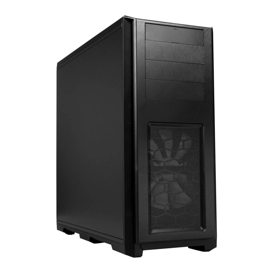
ENTHOO PRO TEMPERED GLASS EDITION
Continuing with the legacy of the Enthoo Series, the Enthoo Pro is a full tower case with many rich features implemented from the award-winning Enthoo Primo. Full tempered glass side panel to showcase all your components.
SPECIFICATIONS
CASE SPECIFICATIONS
| Dimension | 235 mm x 535 mm x 550 mm (W x H x D) |
| Form Factor | Full tower |
| Material(s) | ABS, Tempered Glass, Steel chassis |
| Motherboard support | ATX, EATX, mATX, SSI EEB |
| Front I/O | 2x USB 3.0, 2x USB 2.0, Mic, Headphone LED Switch |
| Side window | Yes, Tempered Glass panel |
EXPANSION & DRIVE BAYS
| Expansion slots | 8 |
| External 5.25" | 3 |
| Internal 3.5" | 6 (2x 3HDD cages) |
| Internal 2.5" | 11 (2x SSD Brackets) |
| COOLING | 120 mm | 140 mm | 200mm |
| Front | 2x (*2x included) | 2x (1x included) | 1x |
| Top | 3x | 3x | 1x |
| Rear | 1x | 1x (1x included) | - |
| Bottom | 2x | 1x | - |
| HDD | 2x | - | - |
*PH-ES614PTG_SWT model only
| LIQUID COOLING | 120 mm radiator | 140 mm radiator |
| Front | Up to 240 | - |
| Top | Up to 360 | Up to 420 |
| Rear | 120 | 140 |
| Bottom | Up to 240 | 140 |
CLEARANCE
| Graphic card Without HDD cages | 347 mm 472 mm |
| CPU cooler | 193 mm |
| Cable management | 27 mm (39mm at PSU area) |
| Radiator Clearance | 65mm to motherboard |
| Model number | PH-ES614PTG |
| Warranty | 5 Years |
EXPLODED VIEW

- Chassis
- Tempered Glass Side Panel
- Right Side Panel
- Front Panel
- ODD Cover
- Bottom Dust Filters
- Top Panel
- Phanteks Logo Plate
- Front Mesh cover
- Hard Drive Cage
- SSD Bracket (2x)
- PH-F140
- Front dust filters
- I/O Ports
- Top Mesh cover with dust filter
- PSU Cover
- Reservoir Bracket
- Bottom Feet
- PH-F120 & PH-FF120RGBP*
![]()

*PH-ES614PTG_SWT model only
ACCESSORIES

BRACKETS
SSD Bracket (2x)

Reservoir Bracket

PSU Cover

I/O PORTS AND FRONT PANEL

- USB 3.0
- USB 2.0
- Microphone
- Headphone
- Power Reset
- LED Switch
- Power Button/HDD LED
*RGB LED Control (6) Instructions:
 | Long Press: On/Off |
 | Short Press (<1sec): Choose LED Color (10 colors) |
 | 2 Sec Press: Choose Mode Mode 1: Static Mode 2: Breathing Mode 3: Color Cycle |
CONNECTIONS
TO MOTHERBOARD

TO PSU

TO PHANTEKS RGB LED STRIPS

Connects Phanteks' multicolor LED strip / Halos fan frames for interior lighting.
PANEL REMOVAL

Unscrew the 2x thumb screws to remove the side panels.

Unscrew the 2x thumb screws to remove the glass panel.
** To prevent damage to the panels, please follow the steps in order.

- Pull outward to remove the front panel.
- Pull up to remove the top panel.
** Use caution when removing front panel, Power LED wires are attached to front panel.
MOTHERBOARD INSTALLATION
- Standoff screws are pre-installed for ATX. Extra standoff required for E-ATX

- Install the motherboard with the provided M3 screws.


POWER SUPPLY INSTALLATION
- Remove PSU cover


- Unscrew the thumb screws.
- Pull out
- lift up on the right side to remove cover
- Install PSU
Use the provided screws to secure the PSU in place.

REAR VIEW


- Install PSU cover
- Align to the three rubber grommets and slide in.

- Use the provided thumb screws to lock in place.


FILTERS REMOVAL
To clean the dust filters, run slow moving water through the filters. Dry filters before reinstalling.
To remove the bottom and front dust filters slide the filters out from the case.

FAN COMPATIBILITY

| FAN COMPATIBILITY TABLE | |||
| 200mm | 140mm | 120mm | |
| Top | 1 | 3 | 3 |
| Bottom | 1 | 2 | |
| Front | 1 | 2 (1x included) | 2 (2x included*) |
| Rear (Top) | 1 (1x included) | 1 | |
| HDD Cages | 2 | ||
*PH-ES614PTG_SWT model only
SSD MOUNTING LOCATION
Four mounting locations for the SSD brackets.

SSD/ODD INSTALLATION
SSD INSTALLATION
Slide in the SSD and screw in from the side to lock in place.

DROP N LOCK
Align corner of bracket to the guide and drop down to lock.

ODD INSTALLATION

Squeeze the two tabs in and push outward from inside the case.

Align and slide in.
HARD DRIVE INSTALLATION
3.5" INSTALLATION

Place hard drive into tray and push in the arms to lock.
2.5" INSTALLATION

Align the SSD onto the mounting holes and screw in.

Align the tray to the HDD cage and slide in.
REMOVING HDD CAGES
Unscrew the thumbscrews to remove the cages.

WATERCOOLING INSTALLATION
WATERCOOLING RADIATOR COMPATIBILITY

120 MM FORM FACTOR RADIATORS
| Radiator Size | Front | Rear | Bottom | Top |
| 120mm |  | | | |
| 240mm | | | | |
| 360mm | |
*
Supported Radiator size and thickness varies depending on your setup.
140 MM FORM FACTOR RADIATORS
| Radiator Size | Front | Rear | Bottom | Top |
| 140mm | | | | |
| 280mm | | |||
| 420mm | |
*
Supported Radiator size and thickness varies depending on your setup.
RESERVOIR BRACKET INSTALLATION

Align the reservoir bracket to the mounting hole and screw into the top of the reservoir bracket. Then use the provide 2x screw to lock the reservoir in place.
MORE RGB
The RGB controller in the Enthoo PRO TG supports up to 5 meters of LED strips. This allows you to expand your LED lighting throughout the entire case.

- INTEGRATED MAGNETS
- QUALITY 3M ADHESIVE
- DURABLE WATERPROOF SILICON HOUSING
- EASY INSTALLATION WITH 1 ORIENTATION CONNECTORS
- EXPANDABLE DAISY CHAIN CONNECTORS
WE PROVIDE THE FOLLOWING RGB LED PRODUCTS:
COMBO SET (NOT INCLUDED)
PH-LEDKT_CMBO
- 2x 40cm magnetic RGB - LED strip
- Extension cable
- Motherboard RGB adapter
- High quality 3M adhesive
400 MM EXTENSION (NOT INCLUDED)
PH-LEDKT_M4
- Easy installation thanks to magnets
- High quality 3M adhesive included
1 M LED STRIP (NOT INCLUDED)
PH-LEDKT_M1
- Easy installation thanks to magnets
- High quality 3M adhesive included
2M LED STRIPS (NOT INCLUDED)
PH-LEDKT_M2
- Easy installation thanks to magnets
- High quality 3M adhesive included
RGB LED ADAPTER
- Also functions as an extension cable
- Allows you to synchronize with other RGB products using the industry standard connector
HALOS FAN FRAMES
PH-FF120RGBP / PH-FF120RGBA / PH-FF140RGBP / FF140RGBA
- Illuminate your fan blades
PWM HUB INSTALLATION (OPTIONAL)
")
Please visit our website for multi-language instructions regarding PWM Hub at www.phanteks.com.
The PWM hub functions optimally when modulated by a PWM signal from the motherboard, which will allow the greatest control range. However, not all 4-pin motherboard connectors implement the PWM signal modulation.
Connecting the 4-pin to CPU_FAN
For full PWM functionality, Phanteks' PWM hub requires users to connect the 4-pin connector to the "CPU_Fan" connector of the motherboard, because all motherboard manufacturers implements a PWM signal modulation on this connector. Connect the SATA 12V power to power the PWM hub. Not all motherboards have their CPU_Fan connector set on PWM signal modulation by default. Please consult your motherboard documentation for this matter.
Connecting the 4-pin to other 4-pin header (besides the CPU_Fan)
Other 4-pin connectors can be found on modern motherboards besides the "CPU_Fan" connector (e.g. "CPU_Fan2", "CHA_Fan", "OPT_Fan"), however not all motherboard manufacturers implement a true PWM signal modulation onto these connectors. These type of 4-pin connectors modulate the RPM by voltage, which has a smaller control range compared to modulation by true PWM signal.
The 12V SATA power cable can not be used to power the PWM hub if connecting to these types of 4-pin connectors, due to the interference with the RPM regulation by voltage (resulting in the fans running on full RPM). The PWM hub will draw its power from the 4-pin connector, which is limited to a total device consuming 30W in total.
Important Note:
1 motherboard connector can only read 1 RPM signal. Therefore, the motherboard will only read the RPM signal from 1 device connected to Fan 1. The RPM form all other devices will be regulated according to FAN 1. Y-splitter should not be connected to FAN 1.
SERVICES AND SUPPORT
If you have any questions or concerns, please visit Phanteks' website for technical support. We consider customer support, satisfaction and feedback an essential element of our overall marketing effort. Please feel free to contact our support team. Thank you!
Contact Us at
USA:
Support@phanteksusa.com
International:
Support@phanteks.com
For Warranty Information, please visit Phanteks' website.
www.phanteks.com
www.phanteksusa.com
www.phanteks.cn
Documents / Resources
References
Download manual
Here you can download full pdf version of manual, it may contain additional safety instructions, warranty information, FCC rules, etc.
Download Phanteks ENTHOO PRO (PH-ES614PTG BK) ENTHOO Series Manual
Advertisement


Need help?
Do you have a question about the ENTHOO Series and is the answer not in the manual?
Questions and answers