Advertisement
INSTRUCTIONS
If you have any questions, please contact us through our customer service or social media.
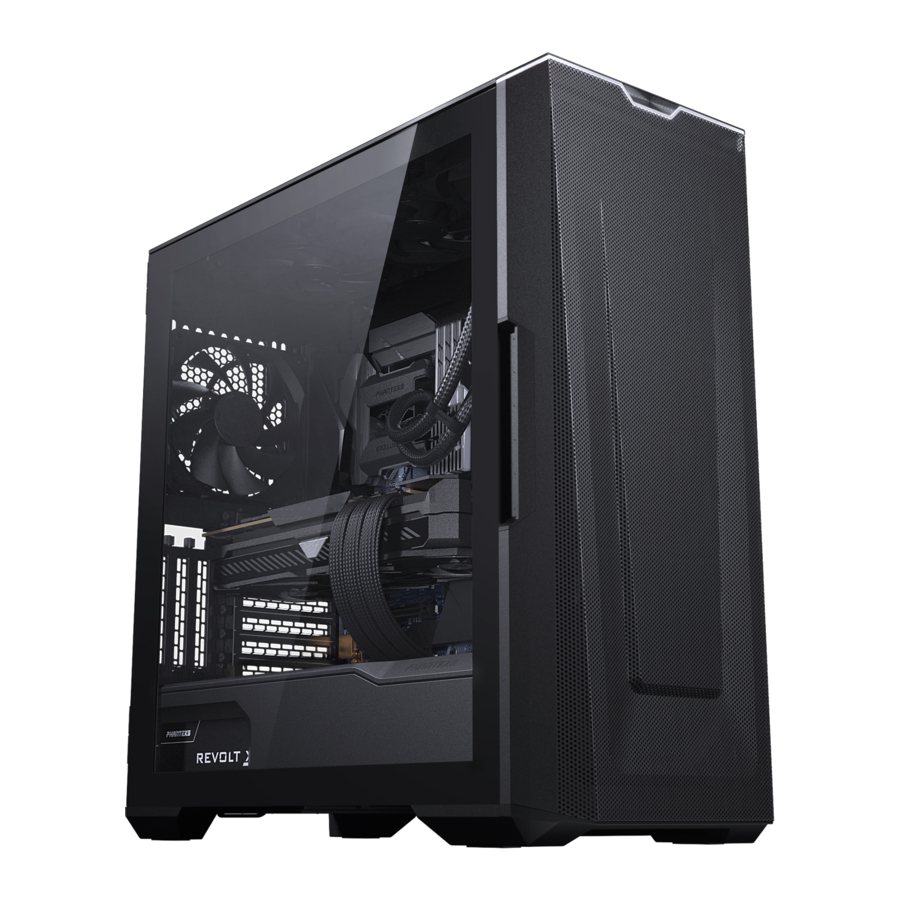
This manual is for the following models:
| PH-EC500GA_DBK01A | D-RGB Satin Black | 3x 140mm D-RGB Fans Black |
| PH-EC500GA_DMW01A | D-RGB Matte White | 3x 140mm D-RGB Fans White |
| PH-EC500GA_BBK01 | Performance | 4x 140mm Fans Black |
| PH-EC500GA_DBK01B | D-RGB Fanless | No Fans |
Phanteks will not take responsibility for any damages incurred due to incorrect installation or usage of this product.
INCLUDED ACCESSORIES

FRONT I/O

D-RGB CONTROLS
Only applicable for the following models:
PH-EC500GA_DBK01A & PH-EC500GA_DMW01A

TURN OFF LEDs
 Press and hold the MODE button for two seconds to turn off LEDs, press again to turn it ON
NOTE | D-RGB control buttons are deactivated when connected to a motherboard.
FAN & RADIATOR SUPPORT
| FANS | FRONT | TOP | REAR |
| 120mm | 3x | 3x | 1x |
| 140mm | 3x | 3x | 1x |
| RADIATOR | |||
| 120mm | up to 360 | up to 360 | up to 120 |
| 140mm | up to 420 | up to 280 | up to 140 |
| CLEARANCE | |||
| CPU Cooler Height | 185 mm | ||
| GPU Length | 435 mm | ||
| Power Supply | 250 mm 195mm If all 4 bottom HDD positions used | ||
| Front Panel Fan Behind front panel | 33 mm | ||
| Front 360 Radiator | 95 mm | ||
| Top 360 Radiator | 70 mm | ||
| Front 420 Radiator | 142 x 475 mm | ||
PANEL REMOVAL
It is recommended to remove all external panels before starting the installation process. The G500A comes with storage cover panels that are behind the right side panel, these support up to 6x 2.5" SSDs next to the 3x 2.5" SSD pre-installed brackets.
LEFT SIDE PANEL
- Open the left side panel and lift upwards to remove it.
![]()

RIGHT SIDE PANEL
- Open the right side panel and lift upwards to remove it.
![]()

COVER PANELS
- To access the storage space, push down the clips on each cover panel to release it.
![]()

FRONT PANEL & DUST FILTERS

Remove the front panel by pulling the panel from below towards you. The top filter can also be remove by pulling it upwards at the rear. The PSU filter can be removed by sliding it outwards.
FRONT FAN BRACKETS
The front fan brackets can be secured in the 120mm fan position by 6x screws.

Out of the box the brackets are set to 140mm position.

HARDWARE INSTALLATION
MOTHERBOARD

Install the ATX motherboard using 9x motherboard screws. For M-ATX Motherboards follow the motherboard instructions to move the stand-offs to the correct position. Use the 'stand-off removal tool' when using a smaller motherboard.
POWER SUPPLY
 PRO TIP
Connect all needed cables to the power supply first for easier installation.

- Remove the PSU bracket first by loosing the 2x thumb screws.
- Install the power supply with 4x PSU screws onto the bracket.
- Place it back into the chassis and tighten the 2x thumb screws.
STORAGE
2.5 SSD
- Slide the SSD Bracket up to remove it from the chassis.
![]()

- Secure the SSD with 4x SSD screws to the SSD Bracket.
![]()


For even more storage, secure the SSD with 4x SSD screws directly onto the panels.
3.5 HDD

Slide the 3.5" HDD into the HDD cage. When installing 2x 3.5" HDD brackets, stack them first before placing it into the chassis.

Slide the HDD bracket into the bottom part of the chassis, make sure they click when installed to be sure it is installed correctly.
PRO TIP
The HDD tray can also hold a 2.5" SSD
- Remove the HDD thumb screw to remove the cable cover(s) on the inside of the chassis.
![]()
- Slide the HDD bracket in, then press it down to secure it.
![]()
- To lock the HDD bracket, use 2x Thumb screws per bracket.
![]()


CABLES

Connect the front I/O cables to the motherboard and power supply.
D-RGB CABLES
Only applicable for the following models:
PH-EC500GA_DBK01A, PH-EC500GA_DMW01A & PH-EC500GA_DBK01B
More D-RGB lighting products can be connected to the integrated D-RGB controller. Optionally, lighting can be connected and controlled via motherboard software.

ANTI-SAG BRACKET
- Make sure to install all GPU & PCI cards beforehand. Place the GPU anti-sag bracket at the back. For easy access, remove the SSD bracket first.
![]()
- Insert the thumbscrews without tightening them.
![]()
- Manually press down the screws (1), then lock the thumbscrews in position (2).
![]()


OPTIONAL UPGRADE
INCLUDED VERTICAL GPU MOUNT
GEN 4 RISER CABLE SOLD SEPARATELY PH-CBRS4.0_FL22
The G500A chassis supports the placement of a vertical GPU with the included vertical GPU mount. The Vertical GPU mount has two mounting positions, A or B as seen at step 03.
- Connect the riser cable to the vertical GPU mount and secure it with 2x long riser cable screws.
![]()
- Secure the Vertical GPU mount on the chassis with 2x PSU screws.
![]()
-
- Position A can hold 3-slot GPU cards.
![]()
- Position B can hold 2-slot GPU cards.
![]()
- Position A can hold 3-slot GPU cards.


GEN 4 VERTICAL GPU BRACKET PH-VGPUKT4.0_03 (GEN 4.0 RISER CABLE INCLUDED)
As an alternative, the G500A supports the Phanteks Vertical GPU Bracket which supports up to a 4 slots GPU. Also this bracket puts the GPU further away from the tempered glass panel for increased airflow.

Documents / Resources
References
Download manual
Here you can download full pdf version of manual, it may contain additional safety instructions, warranty information, FCC rules, etc.
Advertisement


Need help?
Do you have a question about the Eclipse G500A and is the answer not in the manual?
Questions and answers