Advertisement
- 1 INTRODUCTION
- 2 LIGHTING EFFECTS
- 3 EXPLODED VIEW
- 4 ACCESSORIES
- 5 SPECIFICATIONS
- 6 REMOVE EXTERNAL PANELS
- 7 REMOVE COVERS
- 8 MOTHERBOARD INSTALLATION
- 9 POWER SUPPLY INSTALLATION
- 10 RADIATOR & FAN POSITIONS
- 11 RECOMMENDED AIRFLOW CONFIGURATIONS
- 12 FAN & RADIATOR INSTALLATION
- 13 POWER BUTTON AND LED
- 14 FRONT I/O
- 15 MOVE FRONT I/O TO SECONDARY LOCATION
- 16 D-RGB CABLES
- 17 INSTALLING STORAGE
- 18 INTERNAL CABLE MANAGEMENT
- 19 INSTALLING LED COVERS
- 20 INSTALLING GPU SUPPORT BRACKET
- 21 EXTERNAL CABLE MANAGEMENT
- 22 SUPPORT
- 23 Documents / Resources
INTRODUCTION
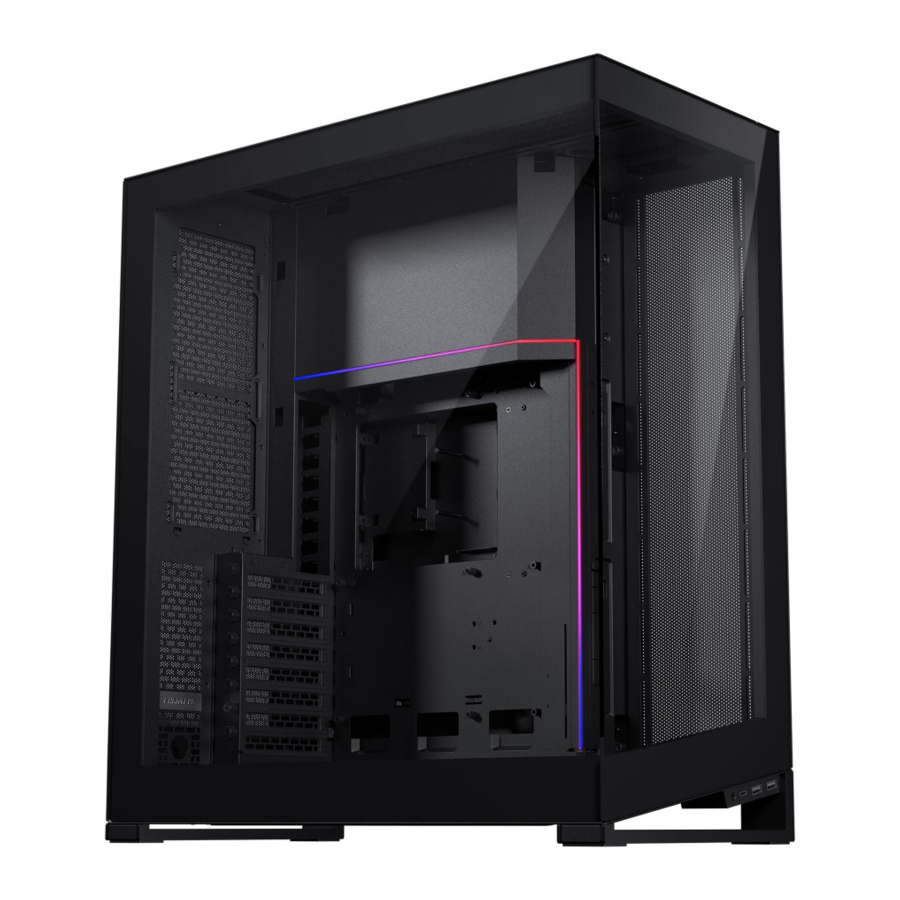
INTRODUCING THE PHANTEKS NV7
The Phanteks NV7 is a showcase full-tower chassis with a clean look from every side. It is the first installment of the new NV series, which is focused on showcasing your hardware in a premium build-quality chassis. Performance is uncompromised with Ultra-Fine Mesh panels while providing a clean and stylish look with the nearly seamless tempered glass front and left side panels.
LIGHTING EFFECTS
The Digital-RGB lighting can be easily controlled with the 4 buttons on top of the chassis:


TURN OFF LEDs
 Press and hold the MODE button for two seconds to turn off LEDs, press again to turn it ON
EXPLODED VIEW

PARTS
- Chassis
- Front glass panel
- Right side mesh panel
- Left glass panel
- Top panel
- Bottom fan bracket
- Side fan bracket
- Rear door
- Bottom dust filter
- Front I/O
- GPU Support Bracket
- Motherboard Cover
- D-RGB Cover
- Top I/O
- Rear Mesh Cover
- Airflow Cover
ACCESSORIES

GPU SUPPORT BRACKET
Included in accessory box

SCREWS

AIRFLOW COVER
2x Included in accessory box
OTHER ACCESSORIES
1x D-RGB Motherboard adapter cable
1x Microfiber Cloth
6x Zipties
1x Manual
SPECIFICATIONS
| CASE SPECIFICATIONS | ||
| Dimension (DxWxH) | 532 x 253 x 586 mm / 20.9 x 10.0 x 23.1 in | |
| Form Factor | Full Tower | |
| Materials | Steel, Tempered Glass front and side panels | |
| Motherboard Support | ATX, micro-ATX, mini-ITX, E-ATX (up to 277 mm wide), SSI-CEB (up to 290 mm w/o cover ) | |
| Front I/O | Power switch, 1x USB 3.2 Gen2 Type-C, 2x USB 3.0, D-RGB Mode, D-RGB Color, D-RGB Speed, D-RGB Channel, Microphone/Headphone | |
| PCI SLOTS & DRIVE BAYS | ||
| PCI Slots | 8x | |
| Internal 2.5" | 6x | |
| Internal 3.5" | 2x | |
| FAN | 120mm | 140mm |
| Side | 4x | - |
| Top | 3x | - |
| Bottom | 3x | 3x |
| Rear | 2x | - |
| RADIATOR | 120mm | 140mm |
| Side | up to 360 | - |
| Top | up to 360 | - |
| Bottom | up to 360 | up to 280 |
| Rear | up to 240 | - |
| INCLUDED ACCESSORIES | ||
| GPU Support Bracket | 1x | |
| Airflow Cover | 2x | |
| Toolbox | 1x | |
| CLEARANCE | ||
| GPU Length | 450 mm / 17.7 in | |
| CPU Cooler Height | 185 mm / 7.3 in | |
| PSU Length | 255 mm / 10.0 in | |
| Side 360 Radiator | Maximum size: 132 x 440 mm | |
| Side 360 Radiator Thickness | 65 mm (to GPU) | |
| Top 360 Radiator | Maximum size: 132 x 440 mm | |
| Rear 240 Radiator | Maximum size: 132 x 320 mm | |
REMOVE EXTERNAL PANELS
- OPEN REAR PANEL
Open the rear door by pulling it from the bottom right corner.
![]()
- REMOVE GLASS SIDE PANEL
Loosen the 2 thumb screws in the rear, slide the glass side panel to the rear and tilt it sideways to remove it.
![]()
- REMOVE GLASS FRONT PANEL
Unscrew the 2 screws from the left side and slide the panel to the left to remove it. Optionally, this panel can be left on during installation.
![]()
- REMOVE TOP PANEL
Loosen the 2 thumb screws of the top panel in the rear. Slide the top panel to the rear to remove it.
![]()
- REMOVE RIGHT SIDE PANEL
Remove the screw on the top and slide the right panel upwards to remove it.
![]()
- REMOVE REAR DOOR
Optionally, remove the back door by sliding it upwards when it is in open position.
![]()


REMOVE COVERS
- REMOVE D-RGB COVER
Slide the D-RGB cover to the front of the chassis to remove it.

- REMOVE MOTHERBOARD COVER
Remove the screw located on the right side of the chassis. Push the motherboard cover down to remove it.


MOTHERBOARD INSTALLATION

- ALIGN MOTHERBOARD
Align the motherboard with the screwholes on the chassis' motherboard tray. - SECURE MOTHERBOARD
Secure the motherboard with 9x motherboard screws.
 PRO TIP
Use the included stand-off tool to easily remove and re-install the motherboard stand-offs for other motherboard form-factors

ATTENTION
For Micro-ATX and SSI-CEB check the motherboard instructions for stand-off locations.
POWER SUPPLY INSTALLATION
- INSERT PSU
Insert the PSU from the right side of the chassis.


PRO TIP
Attach all PSU cables first before installing the PSU into the chassis.
- SECURE PSU
Secure the PSU from the rear with 4x PSU screws.
![]()

RADIATOR & FAN POSITIONS

RADIATOR POSITIONS
Side: up to 360
Bottom: up to 360/280
Top: up to 360
Rear: up to 240

FAN POSITIONS
Side: 4x 120 mm
Bottom: 3x 120/140 mm
Top: 3x 120 mm
Rear: 2x 120 mm
RECOMMENDED AIRFLOW CONFIGURATIONS
AIR-COOLED CONFIGURATION

Side: Intake
Bottom: Intake
Top: Exhaust
Rear: Exhaust
WATER COOLED CONFIGURATION

Side: Exhaust
Bottom: Intake
Top: Exhaust
Rear: Exhaust
FAN & RADIATOR INSTALLATION
SIDE FAN/RADIATOR BRACKET
- REMOVE SCREW
Remove the screw located on the top.
![]()
- PULL & TAKE OUT BRACKET
Remove the bracket by pulling the handle at the top of the bracket and take it out.
![]()
- INSTALL FANS/RADIATOR
Install up to 4x 120 fans/360 radiator on the bracket.
![]()
- INSTALL SIDE BRACKET
Re-install the bracket and secure it with the screw located on the top.
Use the 3 cut-outs to route all fan cables.


PRO TIP
Use the provided airflow cover for optimal airflow. When used, the airflow will be closed off.
BOTTOM FAN/RADIATOR BRACKET
- REMOVE BOTTOM BRACKET
Release the bracket by removing the rear thumb screw. Slide the bracket to the front to remove it.
![]()
- INSTALL FANS/RADIATOR
Install up to 3x 120mm / 3x 140 mm fans and/or 280/360 radiator on to the bracket.

- RE-INSTALL BOTTOM BRACKET
Re-install the bracket by sliding it towards the rear and secure it with the thumb screw.


It is possible to install the bracket the other way around for angled fans.
Fan cables can be routed through the cut-outs on the rear and side.

REAR FAN/RADIATOR POSITION
The rear has space for up to 240 radiator and 2x 120 fans. The fans can be installed in front of the rear panel while the radiator can be installed behind the rear panel.

- REMOVE REAR MESH PANEL
Remove the screw on the rear and remove the mesh panel. - INSTALL FANS/RADIATOR
Install up to 2x 120 fans on the inside of the rear chassis. A 240 radiator can be installed on the outside of the rear chassis. - RE-INSTALL REAR MESH PANEL
If no radiator is installed, re-install the rear mesh panel.
Fan cables can be routed through the cut-outs on the rear.
TOP FAN/RADIATOR POSITION
- INSTALL FANS/RADIATOR
Up to 3x 120 fans/360 radiator can be directly installed into the top of the chassis.
Fan cables can be routed through the cut-outs on the top.


POWER BUTTON AND LED
- CONNECT POWER BUTTON
Connect the power switch module to the motherboard.
![]()


FRONT I/O
I/O INTERFACE

- USB 3.1 GEN 2 TYPE-C (1x)
- USB 3.0 TYPE-A (2x)
- Headphone/microphone (1x)
CONNECT I/O CABLES TO MOTHERBOARD

- CONNECT USB 3.1 GEN 2 TYPE-C
![]()
- CONNECT USB 3.0 TYPE-A
![]()
- CONNECT HD AUDIO
![]()


MOVE FRONT I/O TO SECONDARY LOCATION

STEPS TO MOVE I/O TO THE REAR
- REMOVE BOTTOM FAN BRACKET
Remove the bottom fan bracket. - REMOVE SCREWS
Unscrew 2x screws located inside the chassis. - SLIDE I/O UNIT OUT
Slide the I/O unit forward and remove it. - PUSH OUT COVER
Push the cover, located on the rear bottom, up to remove it. - SLIDE I/O UNIT IN
Pull the cables through the cutout and slide the I/O unit into the rear position. - SECURE I/O UNIT
Secure the I/O unit in its new position with 2x screws.
PRO TIP
The secondary Front IO location in the rear is great for a clean look.
D-RGB CABLES
D-RGB CONTROLLER
The built-in D-RGB controller has 2 channels (A & B). Both channels, each with 2 available D-RGB ports, can be controlled seperately with the control buttons on the front I/O.
max 7A per channel, max 4A per port

LIGHTING EFFECTS & CONTROLS
D-RGB Lighting effects and control instructions are described in the "LIGHTING EFFECTS" section.
- CONNECT THE SATA CABLES
Connect the 2x SATA cables to the power supply.

- EXPAND WITH OTHER D-RGB PRODUCTS
To Phanteks Digital-RGB products (JST connector)
![]()
- SYNC LIGHTING TO MOTHERBOARD (OPTIONAL)
The D-RGB to motherboard cable is included in the accessory box.


INSTALLING STORAGE
TOP DOOR STORAGE
- OPEN TOP DOOR
Loosen the thumb screw to open the top door.
![]()
- INSTALL 2.5'' DRIVES
Install up to 2x 2.5'' drives with 2x SSD screws per SSD.


BOTTOM DOOR STORAGE
- OPEN BOTTOM DOOR
Loosen the thumb screw to open the door. - INSTALL DRIVES
The bottom door can be used for one of the following storage options:
1x 3.5'' + 4x 2.5'' | 4x 2.5'' | 2x 3.5''

OPTION A- 1X 3.5'' + 4X 2.5''

OPTION B - 4X 2.5''
- Reposition the 2.5'' drive bracket to the rear of the motherboard.
- Install 2x 2.5'' drives on the door and 2x 2.5'' drives on the bracket

OPTION C - 2X 3.5''
- Remove the 2.5'' drive bracket completely.
- Install 2x 3.5'' drives with cables routed to the top
INTERNAL CABLE MANAGEMENT
PSU CABLE MANAGEMENT
The PSU cables can be routed like the image below for clean cable management. Open the top cover door to loop the CPU & MB cables to get rid of excessive cable length.


Loop excessive cable length on the inside of the top cover door.
INSTALLING LED COVERS
INSTALL MOTHERBOARD COVER
The motherboard cover can be installed in two ways:

Option 1: Default
The first option covers a bit more of the cables attached to the motherboard, and is a great fit for standard sized ATX motherboards.

Option 2: Reversed
For the second option, the cover is installed in reversed position. This covers less of the motherboard and allows more clearance for E-ATX motherboards (up to 277 mm).
Option 3: Remove Cover
For even larger motherboards and maximum clearance, it is recommended to remove this cover completely.

After choosing the preferred position, align the motherboard cover (1) and slide upwards (2). Secure it with the thumb screw through the right side of the chassis (3).
INSTALL D-RGB COVER

Slide the D-RGB cover to the rear of the chassis to install it.
INSTALLING GPU SUPPORT BRACKET
(OPTIONAL)
- INSTALL BRACKET
Install the GPU support bracket on the motherboard cover with 1x thumb screw.

- ADJUST HEIGHT
Adjust to the correct height for your GPU and use the thumb screw to secure it.
![]()
- ADJUST DEPTH
Adjust the depth of the bracket to hold the GPU tightly and lock with 1x thumb screw underneath the bracket.


PRO TIP
Use the tie point on the bracket to tie down GPU cable for a clean routing
EXTERNAL CABLE MANAGEMENT
CABLE LANES
External cables can be managed with the cable lanes behind the rear door. The left lane is larger and can be used for thick cables. The other three lanes are smaller and made for thin cables.

VELCRO TIE

Use the velcro tie on the bottom to tie all cables down to the chassis.
COMB OR GROMMET
There are two options for the cables to leave the case:

Option 1: Rear comb
The rear comb can be used to seperate each cable to leave the case neatly.

Option 2: Bottom grommet
Alternatively, the grommet on the bottom of the chassis can be used to lead the cables out.
SUPPORT
INTERNATIONAL
RMA & Technical Support
E-mail
support@phanteks.com
AMERICAS
RMA & Technical Support
Hours
Monday - Friday 09:00 - 05:00 PST
Phone Number
+1 (909) 598 2115
E-mail
support@phanteksusa.com
For the latest information on the product, service and warranty please visit www.phanteks.com
Documents / Resources
References
Download manual
Here you can download full pdf version of manual, it may contain additional safety instructions, warranty information, FCC rules, etc.
Advertisement


Need help?
Do you have a question about the NV7 and is the answer not in the manual?
Questions and answers