Advertisement
General information
This manual is a key component for a safe and damage-free assembly, use and maintenance of your bike. It provides you with the most important information for your bike, helps you assemble your bike and gives you tips that are helpful for the entire life of your bicycle. If you have any doubts or uncertainties about working on your bike, please consult a qualified bicycle mechanic.
Please read this manual carefully before taking the first ride on your new bike and make sure you understand everything. Ensure that third-party users are also informed about the contents of this manual and that they understand and follow all instructions.
Keep this manual for future reference. If you sell or give away your bike, please also include this manual.
This manual is also available on rosebikes.com/manuals.
Explanation of symbols used
 ...indicates a hazard with a high level of risk which, if not avoided, will result in death or serious injury. |
 ...indicates a hazard with a low level of risk which, if not avoided, may result in minor or moderate injury. |
 NOTE NOTE ...indicates a hazard for material goods. |
Target group
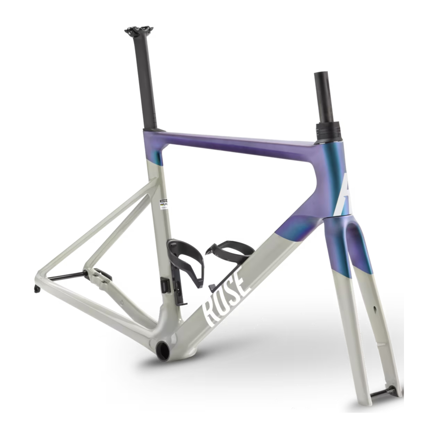
This manual is intended for you, the owner of the XLITE frame.
Assembly and maintenance of the frame require basic knowledge in bicycle technology. If in doubt, please consult a qualified bicycle mechanic. Improper assembly or incorrect maintenance of your bike may result in serious accidents with fatal consequences!
Tools
All work on your bicycle requires the use of appropriate tools. Screw connections must be tightened to a defined torque using an appropriate torque wrench.
A proper installation and removal of components can only be guaranteed when using perfectly functioning and undamaged tools.
The special properties of carbon
Carbon frames must not be clamped (e.g. into a workstand) or subjected to pressure in any other way. Always tighten carbon parts to the prescribed torque.
Damages to carbon components might not show up immediately. If in doubt, please consult a qualified bicycle mechanic.
Carbon parts have a limited lifespan. Carbon components should be replaced regularly (e.g. every three years). We recommend replacing ROSE frames and forks made from carbon every six years.
Heat permanently damages the carbon structure. Carbon parts must not be stored close to heat sources or in a vehicle in direct sunlight.
Selecting components
The components must be selected taking into account the mounting points (see ""Technical details"), the intended use (see "Intended use") and the maximum system weight (see "Weight limit" ).
Do not mount any luggage rack, bike trailer or child bike seat to the bike.
Warranty and guarantees
For all information on warranty and guarantee see rosebikes.com/termsandconditions.
If you want to make a warranty claim for your bike or individual components, you are obliged to return the entire bike and not just the defective components. This is the only way we can check whether the requirements for statutory warranty claims have been met.
Parts subject to wear
The components listed below should be checked regularly and replaced, if necessary:
- Headset
- Stickers and paint
Weight limit
The ROSE XLITE frame is designed for a maximum weight of 110 kg. The system weight is derived from the weight of the cyclist, bicycle, gear (helmet, backpack, shoes, clothes) and luggage.
If components with a lower maximum system weight are installed, the maximum system weight of the whole system is reduced to the value of the component with the lowest value
Exclusion of liability
The activities described in this manual should only be carried out by people with sufficient expertise.
The user is liable for damages resulting from:
- Misuse or any other cause beyond the range of the intended use (see "Intended use")
- Non-compliance with safety regulations
- Improper assembly, repair and maintenance
- Use of unapproved replacement parts and accessories
- Modification to the frame
If in doubt, please consult the ROSE service team or a qualified bicycle mechanic.
Safety
| Risk of accident due to improperly assembled or incompatible components and accessories! Incorrectly fitted or incompatible components or accessories can come loose during the ride, break or cause damage to the frame!
|
| Risk of accident due to sudden failure of pre-damaged components! A fall or unplanned riding manoeuvres can cause unnoticed damages to your frame or components. Pre-damaged components could deform or break while riding.
|
| Risk of accident due to improper handling! If the bike or components are handled improperly, parts of the bike can suddenly fail.
|
The rider's duty of care
Following the instructions specified in this manual does not absolve the riders from their duty of care to ensure that their bike is always in good condition. If there are any questions, consult a qualified bicycle mechanic or the ROSE service team.
Intended use
The intended use for ROSE bikes is divided into six different categories – ranging from use on paved roads through to downhill or freeride use. The bikes must only be used in accordance with their intended purpose/use. Otherwise, the user takes responsibility.
The XLITE frame is approved for use in category 6!
If the bike is to be used in accordance with the provisions of category 6, all attached parts must also be approved for this category!
Category 1
Includes all bikes and e-bikes that should only be used on normal, paved roads, where the tyres are permanently touching the ground at the average speed and there are only occasional light drops.
Average speed 15 to 25 km/h
Recommended rider skills: no particular rider skills necessary
Height of drops: <15 cm
Category 2
Includes all bikes and e-bikes that can be used in conditions described under category 1, as well as on unpaved roads and gravel paths with moderate inclines and descents. These conditions can lead to contact with uneven terrain and the tyre repeatedly losing contact with the ground. Drops are limited to a height of 15 cm or less.
Average speed 15 to 25 km/h
Height of drops: <15 cm
Recommended rider skills: none
Category 3
Includes all bikes and e-bikes that can be used in conditions described under category 1 and 2, as well as on rough trails, uneven and unpaved streets, as well as difficult terrains and undeveloped paths. Also applies to bikes that require technical knowledge to ride. Jumps and drops should not exceed 60 cm.
Average speed: not relevant
Height of drops and jumps: <60 cm
Recommended rider skills: technical skills and practice required
Category 4
Includes all bikes and e-bikes that can be used in conditions described under category 1, 2 and 3, as well as for downhill rides on unpaved roads at speeds under 40 km/h. Jumps should not exceed 120 cm.
Average speed: not relevant
Height of drops and jumps: <120 cm
Recommended rider skills: technical skills, practice and good bike control required
Category 5
Includes all bikes and e-bikes that can be used in conditions described under category 1, 2, 3 and 4, and that are designed for extreme jumps or downhill rides on unpaved roads at speeds of more than 40 km/h or a combination of the above.
Average speed: not relevant
Height of drops and jumps: >120 cm
Recommended rider skills: excellent technical skills, practice and bike control required
Category 6
Includes all bikes and e-bikes that can be used in conditions described under category 1 and that are also used for high speeds of more than 50 km/h, such as for downhill and sprints.
Average speed 30 to 55 km/h
Height of drops: <15 cm
Recommended rider skills: technical skills and practice required
Installation
Mounting the derailleur hanger

The XLITE frame is supplied with two derailleur hangers, with the short derailleur hanger fitted.
- short derailleur hanger: SRAM, Campagnolo, Shimano direct attachment
- long derailleur hanger: Shimano direct mount
Follow the steps below to change the derailleur hanger:
- Unscrew the screw of the mounted derailleur hanger and remove the derailleur hanger.
- Clean the mounting surface of the derailleur hanger and the dropout.
- Fit the derailleur hanger form-fitting, screw in the bolt and tighten it with a torque of 2 Nm.
Headset

The headset of the ROSE XLITE is ready for the brake hoses and shift cables to pass through. Depending on the stem used, the cables can be fully or semi-integrated. Full integration is only possible when using a corresponding ROSE stem or a ROSE One Piece Cockpit.
The spacers supplied come in two parts and can be fitted together without tools.
Laying brake hoses


 Brake hose rear wheel
 Brake hose front wheel
The brake hoses can be routed through the headset and installed in the frame. The front brake hose must be routed through the headset on the non-drive side and the rear brake hose on the drive side (A). To fit the front brake hose, we recommend fixing it to the steerer tube slightly above the opening in the steerer tube using adhesive tape (B).
The rear brake hose can be routed through the supplied foam tube to prevent rattling while riding. The foam tube can be pushed over the head tube into the frame before the hose is laid. Additional fixing is not required. Make sure that the rear brake hose is routed through the bottom bracket shell above the bottom bracket (C).
Follow the brake manufacturer's instructions for shortening, fitting and bleeding the brake.
Laying gear cables

 Cable for rear derailleur
 Cable for front derailleur
 Brake hose rear wheel
 Brake hose front wheel

The cable housing of a mechanical shifting system can be routed through the headset and laid in the frame. The front derailleur cable must be routed through the headset on the non-drive side and the rear derailleur cable on the drive side.
Both cable housings can be guided through the foam tube supplied to prevent rattling while driving. The foam tube can be slid over the head tube into the frame before the cable housings are installed. Additional fixing is not required. Make sure that the cable housing of the rear derailleur is routed through the bottom bracket shell above the bottom bracket.
The brake hoses must be positioned in front of the cable housings in the recesses of the headset caps when viewed in the direction of travel.
When shortening, fitting and adjusting the shifting system, follow the manufacturer's instructions.
Fitting the Di2 battery and routing the cables

If a Shimano Di2 shifting is installed, the battery can be mounted in the seat post using the holder supplied. The cables for the front derailleur and rear derailleur can be laid in the frame and routed out of the frame just before the connection point.
Follow the Shimano instructions for plugging in the connectors and use the tools provided.
Mounting the brake

Brakes with a flat mount can be fitted to the rear brake mount of the ROSE XLITE frame without an adapter for a 140 mm disc or with an adapter for a 160 mm disc. In both cases, make sure the screw length is suitable. Also check whether the brake calliper has sufficient space to the frame strut when mounted without an adapter.
Installing a front wheel with ROSE thru axle
| Risk of accident due to incorrectly assembled wheels! Improperly fitted front or rear wheel axles might suddenly loosen during the ride, which may loosen or block the wheel!
| |
| | A bike work stand can help you assemble the front wheel. When using a work stand make sure to install the seat post first so that you can clamp the bike into the assembly stand at the seat post. |
The lever of the ROSE thru axle can be removed and used for the front or rear wheel. To do this, press the two unlocking buttons on the side.

Installing the front wheel

- Remove the thru axle from the fork.
- Check whether there is an elastic band on the front brake lever. Remove the elastic band if present.
- If present, remove the pad spacer that is fitted between the brake pads. → Keep the pad spacer for future transport of your bike.
- Position the front wheel into the dropouts of the fork.
- Slide the thru axle from the brake side through the fork dropouts and the hub of the wheel.
- Completely thread the thru axle into the fork dropout.
- Turn the lever clockwise and secure it by hand as tightly as possible to a minimum torque of 15 Nm.
- Verify the secure fit of the front wheel.
Installing seat post and saddle
| Raising the seat post below the minimum insertion mark may cause accidents or damage! If the seat post is not inserted to the minimum insertion mark, it may break or damage the frame.
|
| NOTE Exceeding the maximum insertion mark may cause damage to the frame! The insertion depth of the frame is limited. The seat post must not be inserted all the way down during riding. |

- Slide the cover upwards.
- Open the clamp bolt.
![warning]() ATTENTION: Do not unscrew the bolt completely!
ATTENTION: Do not unscrew the bolt completely! - Carefully slide the seat post into the seat tube until you have reached the desired saddle height.
- Tighten the clamp bolt to a torque of 7 Nm and slide the cover downwards.
- Get on your bike and check whether the seat post height is right.
 ATTENTION: Do not unscrew the bolt completely!
 NOTE: If the post is completely removed from the frame, the parts of the seat post clamp should be held so that they cannot fall into the frame.
Adjusting the saddle angle
Adjusting the saddle angle on a saddle with one bolt clamp

- Loosen the clamp bolt by about 2 turns.
![warning]() ATTENTION: Do not unscrew the bolt completely!
ATTENTION: Do not unscrew the bolt completely! - Adjust the position and the angle of the saddle according to your preferences.
- Tighten the clamp bolt to a torque of 12 Nm.
Maintenance
| Risk of accident due to overdue maintenance and service! When neglecting servicing and maintenance, worn or damaged components may cause accidents.
|
Regular maintenance and care is the only way to ensure that all parts of the bike function perfectly. The required maintenance and inspection activities must be carried out by a person with the necessary qualifications.
| COMPONENTS | TASK | INTERVAL |
| Frame | Check the torques of the bolt connections. | for the first time after 100 km then every 200 km |
| Visually inspect the frame for damage such as cracks or deformation. If in doubt, please consult the ROSE service team or a qualified bicycle mechanic! If damage is discovered, the frame may no longer be used. Contact ROSE Service immediately! | after every ride and after a crash | |
| Headset | Disassemble the headset, clean, lubricate and re-assemble it. Replace bearings that don't run smoothly or that show signs of corrosion. | annually or after 200 hours of use |
| Seat post | Disassemble the seat post, clean the seat post and the frame's seat tube. Coat the seat post with assembly paste before mounting it. | after 3 months or 60 hours of use |
| Components | The maintenance activities and intervals for the components must also be carried out in accordance with the respective manufacturer's instructions! | |
Technical details
| Bottom bracket | Pressfit BB86 |
| Front wheel axle | 12 x 100 mm |
| Rear wheel axle | 12 x 142 mm |
| Brake mount front wheel | Flat Mount 140 mm |
| Brake mount rear wheel | Flat Mount 140 mm Note that the chain stays are 20 mm thick when selecting the fixing bolt for the brake calliper (see also "Mounting the brake"). |
| Ø Brake disc | Front and rear wheel: 140 mm, with use of an adapter max. 160 mm. When using a 140 mm disc, check the installation space of the brake calliper. |
| Seat post Ø | D-shape |
| max. | tyre width700 x 32c |
| max. chainring size | 54/40 |
| Bottle Cages | 2 |
Torques

Spare parts and accessories

At https://www.rosebikes.com/manuals, "Frame Details" are available for each bike model. Here you will find all spare parts, torque values and other specific details for your bike.
Documents / Resources
References
Download manual
Here you can download full pdf version of manual, it may contain additional safety instructions, warranty information, FCC rules, etc.
Advertisement


Need help?
Do you have a question about the XLITE and is the answer not in the manual?
Questions and answers