SOLIS S6, S6-GR1P(7-10)K03-NV-ND - Inverter Manual
- User manual ,
- Manual (50 pages) ,
- Installation and operation manual (29 pages)
Advertisement
- 1 Introduction
- 2 Overview
-
3
Installation
- 3.1 Mounting the Inverter
-
3.2
Electrical Connections
- 3.2.1 Connect PV side of inverter
- 3.2.2 AC output connections
- 3.2.3 External ground connection
- 3.2.4 Max. over current protection device (OCPD)
- 3.2.5 Inverter monitoring connection
- 3.2.6 Electrical connection diagram
- 3.2.7 Meter Connection(optional)
- 3.2.8 CT connections(optional)
- 3.2.9 Logic interface connection
- 4 Commissioning
- 5 Operation
- 6 Maintenance
- 7 Troubleshooting
- 8 Specifications
- 9 Safety Instructions
- 10 Documents / Resources
Introduction
Product Description
Solis S6 Single Phase Inverters integrate DRM and backflow power control function, that could suitable for smart grid requirement.
This manual covers the S6 Single Phase Inverter model listed below:
S6-GR1P7K03-NV-ND, S6-GR1P8K03-NV-ND, S6-GR1P9K03-NV-ND, S6-GR1P10K03-NV-ND


Packaging
When you receive the inverter, please ensure that all the parts listed below are included:
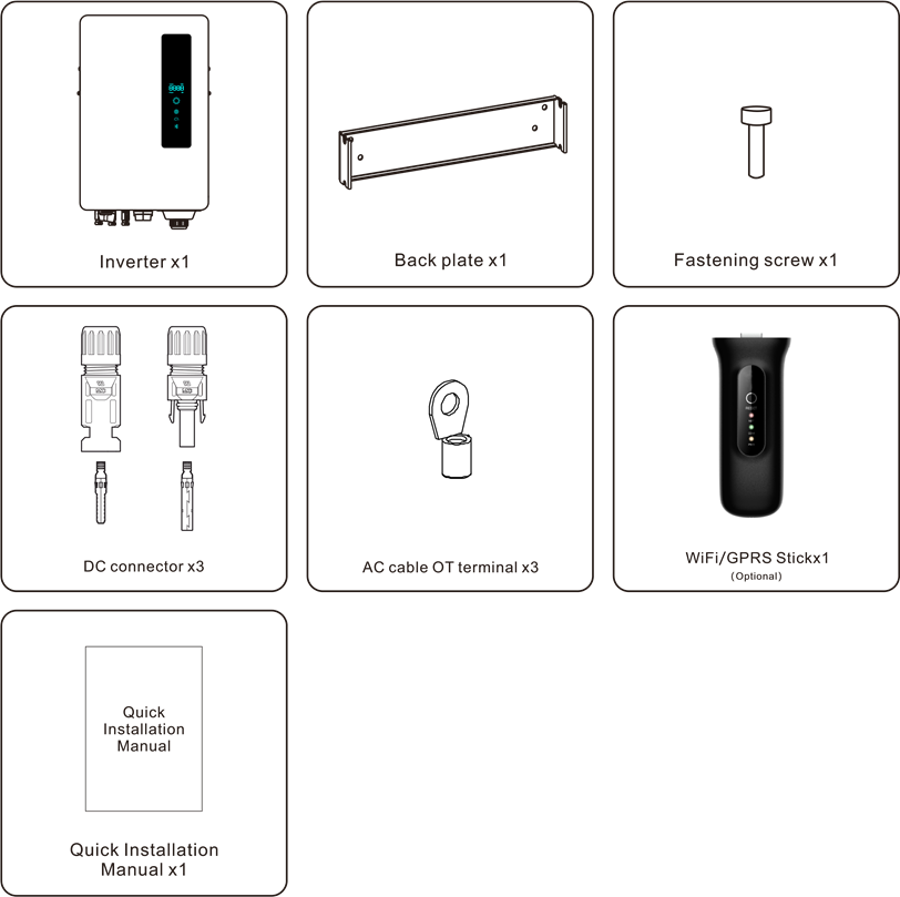
If anything is missing, please contact your local Solis distributor.
Product Storage
If the inverter is not to be installed immediately, storage instructions and environmental conditions are below:
- Use the original box to repackage the inverter, seal with adhesive tape with the desiccant inside the box.
- Store the inverter(s) in a clean and dry place, free of dust and dirt.
- Storage temperature must be between -40℃ and 70℃ and the humidity should be between 0 and 95% non-condensing.
- Stack no more than four (4) inverters high.
- Keep box(es) away from corrosive materials to avoid damage to the inverter enclosure.
- Inspect packaging regularly. If packaging is damaged(wet, pest damage, etc), repackage the inverter immediately.
- Store the inverter(s) on a flat, hard surface - not inclined or upside down.
- After long-term storage, the inverter needs to be fully examined and tested by qualified service or technical personnel before using.
- Restarting after a long period of non-use requires the equipment to be inspected and, in some cases, the removal of oxidation and dust that has settled inside the equipment will be required.
Overview
Front Panel Display
There are four indicators on the Solis S6-GR1P(2.5-6)K-S Series Inverter(Power, COM, CT/Meter and Bluetooth) which indicate the working status of the inverter.

 NOTE:
NOTE:
NOTE:
Long press the Power button for 5 seconds to reset the bluetooth connection passwords. If the reset is successful, the Power button will be flashing in Blue color and in 0.5s interval for 3s. If the reset is failed, the Power button will be flashing in Yellow color and in 0.5s interval for 3s.
Select a Location for the Inverter
To select a location for the inverter, the following criteria should be considered:

Risk of fire
Despite careful construction, electrical devices can cause fires.
- Do not install the inverter in areas containing highly flammable materials or gases.
- Do not install the inverter in potentially explosive atmospheres.
- The mounting structure where the inverter is installed must be fireproof.
- Do not install in small closed spaces where air can not circulate freely. To avoid overheating, always make sure the flow of air around the inverter is not blocked.
- Exposure to direct sunlight will increase the operational temperature of the inverter and may cause output power limiting. Recommends inverter installed to avoid direct sunlight or raining.
- To avoid over heating ambient air temperature must be considered when choosing the inverter installation location. Recommends using a sun shade minimizing direct sunlight when the ambient air temperature around the unit exceeds 104°F/40°C.


Installation
- Install on a wall or strong structure capable of bearing the weight.
- Install vertically with a maximum incline of +/- 5°.If the mounted inverter is tilted to an angle greater than the maximum noted, heat dissipation can be inhibited, and may result in less than expected output power.
- When 1 or more inverters are installed in one location, a minimum 12 inches clearance should be kept between each inverter or other object. The bottom of the inverter should be 20 inches clearance to the ground

- Visibility of the LED status indicator lights and the LCD located at the front panel of the inverter should be considered.
- Adequate ventilation must be provided if the inverter is to be installed in a confined space.

NOTE:
Nothing should be stored on or placed against the inverter.
Mounting the Inverter
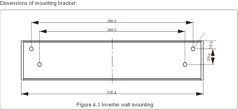
Please see Figure 4.4 and Figure 4.5 for instruction on mounting the inverter..
The inverter shall be mounted vertically. The steps to mount the inverter are listed below.
- According to the figure 4.2, select the mounting height of the bracket and mark the mounting holes. For brick walls, the position of the holes should be suitable for the expansion bolts.

![]()
The inverter must be mounted vertically. - Lift up the inverter (be careful to avoid body strain), and align the back bracket on the inverter with the convex section of the mounting bracket. Hang the inverter on the mounting bracket and make sure the inverter is secure (see Figure 4.5).


Electrical Connections
Connect PV side of inverter
The electrical connection of the inverter must follow the steps listed below:
- Switch the Grid Supply Main Switch (AC) OFF.
- Switch the DC Isolator OFF.
- Assemble PV input connector to the Inverter.
 Before connecting inverter, please make sure the PV array open circuit voltage is within the limit of the inverter.
Maximum 550Vdc for
S6-GR1P7K03-NV-ND, S6-GR1P8K03-NV-ND,
S6-GR1P9K03-NV-ND, S6-GR1P10K03-NV-ND
Before connection, please make sure the polarity of the output voltage of PV array matches the"DC+"and"DC-"symbols.
Please don't connect PV array positive or negative pole to the ground, it could cause serious damages to the inverter.
| Cable type | Cross section(mm²) | |
| Range | Recommended value | |
| Industry generic PV cable (model: PV1-F) | 4.0~6.0 (12~10AWG) | 4.0(12AWG) |
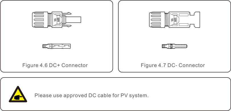
The steps to assemble the DC connectors are listed as follows:
- Strip off the DC wire for about 7mm, Disassemble the connector cap nut. (see Figure 4.8)
- Insert the wire into the connector cap nut and contact pin. (see Figure 4.9)

- Crimp the contact pin to the wire using a proper wirecrimper. (see Figure 4.10)
- Insert the contact pin to the top part of the connector and screw up the cap nut to the top part of the connector.(see figure 4.11).
- Then connect the DC connectors to the inverter. Small click will confirm connection. (see figure 4.12)


If DC inputs are accidently reversely connected or inverter is faulty or not working properly, it is NOT allowed to turn off the DC switch as it will damage the inverter and even leads to a fire disaster.
The correct actions are:
- Use a clip-on ammeter to measure the DC string current.
- If it is above 0.5A, please wait for the solar irradiance reduces until the current decreases to below 0.5A.
- Only after the current is below 0.5A, you are allowed to turn off the DC switches and disconnect the PV strings.
Please note that any damages due to wrong operations are not covered in the device warranty.
AC output connections
It is recommended to use 6-16mm2 outdoor cables with a crimp terminal range of 6-10mm2.
Installation steps are shown as below:
- Strip the end of the AC cable insulation sleeve about 55mm then strip a short bit (S2) on the end of each wire.

![information]() NOTE:
NOTE:
S2 (the length to strip the wire is about 8mm) which is 2-3mm longer than S1. - Insert the stripped cable into the crimping area of the OT terminal then use crimping tool to crimp the cable terminal.

The terminal part must be insulated with heat shrink tubing or insulating tape.
NOTE:
If aluminum cables are used, please use copper and aluminum terminals to avoid direct contact between the copper bar and the aluminum cables. (the copper and aluminum adapters are configured according to the selected cable)
- Dissemble the 4 screws on the AC terminal cover and take out the cover.

- Insert the cable through cap nut, tubing and AC terminal, Insert the 3 cables into AC terminal and use the slotted screwdriver to tighten the screws with torque of 2-3Nm.


When assembling the AC terminal, be careful not to cut the insulation layer of the wire, or it might lead to poor contact.
- Push the AC terminal along the rail to the inside of the inverter then tighten the screws.
Lock the 4 screws of the AC terminal then tighten the cap nut.
External ground connection
An external ground connection is provided at the right side of inverter.
Prepare OT terminals: M4. Use proper tooling to crimp the lug to the terminal.
Connect the OT terminal with ground cable to the right side of inverter.
The torque is 20 in-lbs (2N.m).

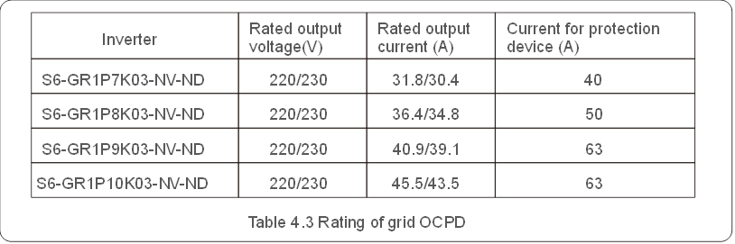
Max. over current protection device (OCPD)
To protect the inverter's AC grid connection conductors, Solis recommends installing breakers that will protect against overcurrent. The following table defines OCPD ratings for the Solis S6 Single Phase Inverters.
Inverter monitoring connection
The inverter can be monitored via Wi-Fi or GPRS. All Solis communication devices are optional (Figure 4.21). For connection instructions, please refer to the Solis Monitoring Device installation manuals.

Electrical connection diagram
Refer to figure 4.22, which is a simple guidance for installing a solar system with PV inverter.
A DC isolator is required to be installed in the system between PV panels with inverter.

- The RCD should be in parallel connection between the consumers mains and the solar supply.
- More than one RCD may be used. Each RCD can protect one or more circuits.
Meter Connection(optional)
The inverter can work with a single phase smart meter to achieve Export Power Management function and/or 24hour consumption monitoring function.
NOTE:
To achieve Export Power Management function, the smart meter can be installed on either grid side or load side. To achieve 24hour consumption monitoring function, the smart meter can only be installed on grid side.
Two types of meters are supported:
Direct Insert Type Meter - Max input current 60A (Model: DDSD1352-C)
External CT Type Meter - 120A/40mA CT is supplied (Model: ACR10RD16TE)
Customer can place the order for a suitable meter from Solis Sales Reps.
Below are the connection diagrams of different meters connecting to different locations.


CT connections(optional)
The inverter can work with a smart sensor to achieve Export Power Management function.
NOTE:
Inverters are classified as "Meter Model" and "CT Model" due to hardware difference.
Meter Model can only connect a smart meter.
CT Model can only connect a smart sensor.
Please consult Solis Sales Rep before placing the order.
NOTE:
To achieve Export Power Management function, the smart sensor must be installed on the grid side.
Below is the connection diagram of the smart sensor.

Logic interface connection
Logic interface is required by some local regulations that can be operated by a simple switch or contactor (Not available in South Africa).
When the switch is closed the inverter can operated normally. When the switch is opened, the inverter will reduce it's output power to zero within 5s.
Pin5 and Pin6 of RJ45 terminal is used for the logic interface connection.
Please follow below steps to assemble RJ45 connector.
- Insert the network cable into the communication connection terminal of RJ45.

- Use the network wire stripper to strip the insulation layer of the communication cable.
According to the standard line sequence of figure 4.26 connect the wire to the plug of RJ45, and then use a network cable crimping tool to make it tight.

- Connect RJ45 to DRM (logic interface).


Commissioning
Preparation
- Ensure all the devices are accessible for operation, maintenance and service.
- Check and confirm that the inverter is firmly installed.
- Space for ventilation is sufficient for one inverter or multiple inverters.
- Nothing is left on the top of the inverter.
- Inverter and accessories are correctly connected.
- Cables are routed in safe place or protected against mechanical damage.
- Warning signs and labels are suitably affixed and durable.
- An Android or IOS mobile phone with Bluetooth function is available.
- Measure DC voltage of PV strings and ensure the polarity is correct.
- Measure AC voltage and frequency and ensure they are within local standard.


APP Download
Users need to download the APP before installing it for the first time.
There are three ways to download and install the latest APP:
- You can visitwww.soliscloud.com to download the latest version APP.
- You can search "Soliscloud" in Google Play or App Store.
![www.apple.com]()
![play.google.com]()
- You can scan this QR code below to download "Soliscloud".


Local Connection via APP
Step 1: Rotate the inverter DC switch from OFF to ON.
Step 2: APP Bluetooth connection with inverter.
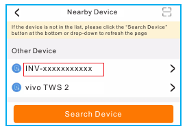
Turn on Bluetooth switch on your mobile phone and then open the Soliscloud APP. Click "More Tools"->"Local Operation"->"Connect with Bluetooth"

Select the Bluetooth signal from the inverter. (Bluetooth Name: INV-Inverter SN)
Step 3: Login account.
If you are the installer, please select the account type as Installer. If you are the plant owner, please select the account type as owner. Then set your own initial password for control verification. (The first log-in must be finished by installer in order to do the initial set up)

Step 4: Grid Code Setting.
Select "Settings->Grid Parameter Setting->Grid Code Setting->Grid Code", choose the applicant standard according to the installation and save.
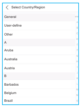
The specific parameters can be set at Grid Code Setting page.
Mention that the grid parameters modification should be permissible by utility grid company or the power distribution supplier.

Step 5: Turn on the AC switch between the inverter and Grid, wait till the inverter start generating.
Stop the Inverter
To stop the inverter, it is mandatory that the steps below are followed in the exact order outlined.
- Select "Power OFF" in the APP.
- Turn off the AC Switch between Solis inverter and Grid.
- Wait approximately 30 seconds (during this time, the AC side capacitors are dissipating energy). If the inverter has DC voltage above the start-up threshold, the red POWER LED will be lit. Switch the DC switch OFF.
- Confirm all LED's switch OFF (~one (1) minute).
Although the inverter DC disconnect switch is in the OFF position and all the LED's are OFF, operators must wait five (5) minutes after the DC power source has been disconnected before opening the inverter cabinet. DC side capacitors can take up to five (5) minutes to dissipate all stored energy.
Bluetooth communication parameters are as follow:
- RF operating frequency range: 2402~2480MHz (BLE, TX/RX)
- Maximum e.i.r.p.: 7.22dBm
Operation
The APP interface contains 4 sections:
- Home
- Info
- Alarm
- Settings
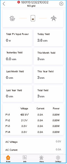
Home Page
The home page contains the power and energy data of the inverter.
The PV data and AC data are also available under this section.
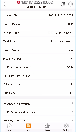
Info Page
Info page displays the general information of the inverter such as inverter serial number, firmware version, grid code, etc.
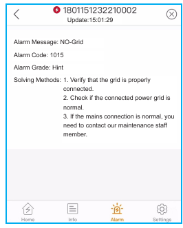
Alarm Page
Alarm page contains the alarm code of the inverter and its corresponding troubleshooting methods.
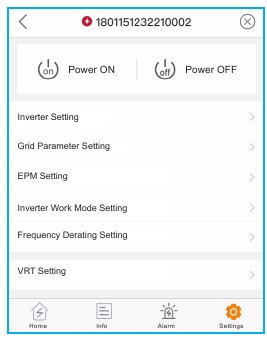
Setting Page
Setting page contains all the setting options of the inverter.
| Functions | Setting Path |
| Switch on/off the inverter | Settings -> "Power ON" & "Power OFF" |
| Change inverter time setting | Settings -> Inverter Setting-> Inverter Parameter Setting -> Inverter Time Setting |
| Change inverter output power percentage or power factor | Settings -> Inverter Setting->Inverter Power Setting |
| Set grid code and protection parameters | Settings -> Grid Parameter Setting ->Grid Code Setting |
| Set Export Power control | Settings -> EPM Setting |
| Set grid code related working modes | Settings -> Inverter Work Mode Setting ->Work Mode |
NOTE:
The inverter is by default setting with grid code which complies with local requirements. If there is need to modify the protection limits, please consult and approve by your local grid operator.
Start up and Stop the inverter
- Select "Settings -> Power ON" to start up the inverter.
- Select "Settings -> Power OFF" to stop the inverter.
Inverter Setting
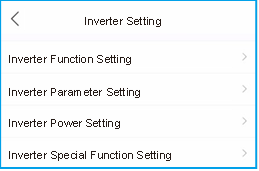
Inverter Function Setting
-
AFCI Setting
| Setting | Description |
| AFCI Protect | Set the inverter AFCI function ON/OFF. |
| Arc-Fault Manual Reset |
|
- 24-Hour Load Monitoring
Turn on this switch to enable 24-Hour Load Monitoring function. Please refer to 6.4.4.1 Built-in EPM Setting for details. - MPPT Multi-peak Scanning Setting
| Setting | Description |
| MPPT Multi-peak Scanning Switch | Set the function ON/OFF. |
| MPPT Multi-peak Scan Interval | The inverter will carry out Multi-peak MPPT scanning 1 time every scan interval. |
- Logical Interface Setup
| Setting | Description |
| Logic Interface(DRM) Switch | Set the function ON/OFF. |
| P_Limit DI 1 ~ P_Limit DI 4 | Set the AC output power under different DI. |
Inverter Parameter Setting
| Setting | Description |
| Time | Set the inverter time and date according to local time zone. |
| Slave Address | Set the inverter address when multiple inverters are installed. |
| Generation Calibration | Calibrate the inverter daily, monthly, annual and total yield. |
Inverter Power Setting
| Setting | Description |
| Output Power Setting | Set the inverter maximum AC output power. |
| PF Curve | Set the inverter power factor. |
| Power Limit | Set the power control slope, power rise control slope, power down control slope, EN 50549 power change gradient after fault trip restart, EN 50549 gradient limit for power-on change. |
Grid Parameter Setting
See Local Connection via APP Chapter for details.
EPM Setting
Built-in EPM is for PV plant with only 1 inverter, while External EPM for multiple inverters.
Built-in EPM Setting
Select "Settings -> EPM Setting -> Built-in EPM Setting" to make the settings.
The Built-in EPM includes 2 functions related to the smart meter or smart sensor.
NOTE:
Function 1: Export Power Management Function
- Inverters can work with a smart meter OR a smart sensor to dynamically limit the export power of the system.
- Zero injection can be achieved.
- Smart meter can be installed either on the grid side OR the load side.
Smart sensor can only be installed on the grid side.
Function 2: 24-Hour Load Monitoring Function
- Only applicable if Solis monitoring system is used.
- Inverters can work with a smart meter OR smart sensor to monitor the load consumption data for the whole day and the data will be displayed on the Solis monitoring system.
- Smart meter or smart sensor can only be installed on the grid side.
NOTE:
Please refer to below instructions for different user scenarios.
Scenario 1. Only Function 1 is required Using a Smart Meter:
Step 1: Refer to Meter Connection Section to connect the smart meter on the grid side or load side.
Step 2: Select the corresponding meter model in the Meter Selection.
Step 3: Choose Meter in Grid Mode or Meter in Load Mode in the Built-in EPM mode selection accordingly.
Step 4: Configure the System Export Power Limit Value to set the allowed backflow power.
Step 5: Configure the Built-in EPM Failsafe Switch to enable the failsafe function (If necessary).
Using a Smart Sensor:
Step 1: Refer to CT connections Section to connect the smart sensor on the grid side.
Step 2: Select the CT Sensor Mode in the Built-in EPM mode selection.
Step 3: Configure the CT Ratio and CT Direction at the "Settings -> EPM Setting -> CT Setting". (If necessary).
Step 4: Configure the System Export Power Limit Value to set the allowed backflow power.
Step 5: Configure the Built-in EPM Failsafe Switch to enable the failsafe function (If necessary).
NOTE:
Please refer to below instructions for different user scenarios.
Scenario 2. Only Function 2 is required Using a Smart Meter:
Step 1: Refer to Meter Connection Section to connect the smart meter on the grid side or load side.
Step 2: Select the corresponding meter model in the Meter Selection.
Step 3: Choose Meter 24-Hour Monitoring Mode in the Built-in EPM mode selection accordingly.
Step 4: Enable the 24-Hour Load Monitoring function at "Settings -> Inverter Setting -> Inverter Function Setting".
Using a Smart Sensor:
Step 1: Refer to CT connections Section to connect the smart sensor on the grid side.
Step 2: Select the CT load Monitoring Mode in the Built-in EPM mode selection.
Step 3: Configure the CT Ratio and CT Direction at the "Settings -> EPM Setting -> CT Setting". (If necessary).
Step 4: Enable the 24-Hour Load Monitoring function at "Settings -> Inverter Setting -> Inverter Function Setting".
NOTE:
Please refer to below instructions for different user scenarios.
Scenario 3. Both Function 1 and 2 are required Using a Smart Meter:
Step 1: Refer to Meter Connection Section to connect the smart meter on the grid side or load side.
Step 2: Select the corresponding meter model in the Meter Selection. Step 3: Choose Meter in Grid Mode or Meter in Load Mode in the Built-in EPM mode selection accordingly.
Step 4: Configure the System Export Power Limit Value to set the allowed backflow power.
Step 5: Configure the Built-in EPM Failsafe Switch to enable the failsafe function (If necessary).
Step 6: Enable the 24-Hour Load Monitoring function at "Settings -> Inverter Setting -> Inverter Function Setting".
Using a Smart Sensor:
Step 1: Refer to CT connections Section to connect the smart sensor on the grid side.
Step 2: Select the CT Sensor Mode in the Built-in EPM mode selection.
Step 3: Configure the CT Ratio and CT Direction at the "Settings -> EPM Setting -> CT Setting". (If necessary).
Step 4: Configure the System Export Power Limit Value to set the allowed backflow power.
Step 5: Configure the Built-in EPM Failsafe Switch to enable the failsafe function (If necessary).
Step 6: Enable the 24-Hour Load Monitoring function at "Settings -> Inverter Setting -> Inverter Function Setting".
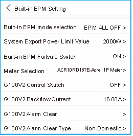
| Setting | Description |
| Built-in EPM mode | 6 built-in EPM mode is optional. Choose the appropriate mode needed. |
| System Export Power Limit Value | Set the permissible PV plant export power to the gird. |
| Built-in EPM Failsafe Switch | When G100 standard is used, this switch is enabled by default. |
| Meter Selection | Select the meter model according to the actual installation. |
| G100V2 Control Switch | When new G100 standard is used, enable this switch. Select the meter or CT mode according to the actual installation. |
| G100V2 Backflow Current | Set the backflow current of the PV plant to the grid. Only meaningful when G100V2 switch is on. |
| G100V2 Alarm Clear | Use this function to clear a fault status according to new G100 standard. Only meaningful when G100V2 switch is on. |
| G100V2 Alarm Clear Type | Select the Domestic or Non-domestic according to the actual installation. Only meaningful when G100V2 switch is on. |
There are 6 modes for Built-in EPM.
- EPM ALL OFF. Built-in EPM function is disabled.
- CT Sensor Mode. Solis Smart Sensor is connected in the grid connection point (The System Export Power Limit Value setting is applicable, default value is 0W).
- Meter in Grid Mode. Solis Smart Meter is connected in the grid connection point (The System Export Power Limit Value setting is applicable, default value is 0W).
- Meter in Load Mode. Solis Smart Meter is connected in the load branch circuit (The System Export Power Limit Value setting is applicable, default value is 0W).
- Meter 24-Hour Monitoring Mode. Solis Smart Meter is connected in the grid connection point(used for 24h load monitoring only, the System Export Power Limit Value setting is not applicable).
- CT load Monitoring Mode. Solis Smart Sensor is connected in the grid connection point (used for 24h load monitoring only, the System Export Power Limit Value setting is not applicable).
External EPM Setting
Select "Settings -> EPM Setting -> External EPM Setting".
External EPM Failsafe Swtich should be turned ON when external EPM device is used.
Inverter Work Mode Setting
Select "Settings -> Inverter Work Mode Setting".
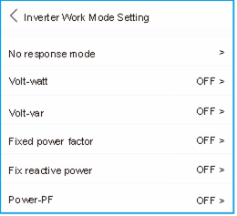
- No response mode
Use this switch to close all response mode. - Volt-watt Mode
The volt-watt mode varies the active power output level of the inverter in response to the voltage at its grid-interactive port. - Volt-var Mode
The volt-var mode varies the reactive power absorbed or supplied by the inverter in response to the voltage at its grid-interactive port. - Fixed power factor Mode
The fixed power factor mode is for control of power factor over the range of inverter output. - Fixed reactive power Mode
The fixed reactive power mode is for control of reactive power over the range of inverter output. - Power-PF Mode
The Power-PF mode varies the active power output level of the inverter in response to its power factor.
Maintenance
Solis S6 Single Phase Inverter does not require any regular maintenance.
However, cleaning the dust on heat-sink will help the inverter to dissipate the heat and increase its life time. The dust can be removed with a soft brush.

Do not touch the inverter's surface when it is operating. Some parts of the inverter may be hot and cause burns. Turn off the inverter and wait for a cool-down period before any maintenance or cleaning operation.
The Screen and the LED status indicator lights can be cleaned with cloth if they are too dirty to be read.
NOTE:
Never use any solvents, abrasives or corrosive materials to clean the inverter.
Troubleshooting
The inverter is designed in accordance with the most important international grid-tied standards and safety and electromagnetic compatibility requirements. Before delivering to the customer, the inverter has been subjected to several tests to ensure its optimal operation and reliability.
In case of failure, the APP will display an alarm message. In this case, the inverter may stop feeding into the grid. The failure descriptions and their corresponding alarm messages are listed in Table 8.1:
| Message Name | Information Description | Troubleshooting Suggestion |
| Grid Over Voltage 01 (1010 DATA:0001) | Over grid voltage |
|
| Grid Over Voltage 02 (1010 DATA:0002) | ||
| Grid Over Voltage 03 (1010 DATA:0003) | ||
| Grid Over Voltage 04 (1010 DATA:0004) | ||
| Grid Over Voltage 05 (1010 DATA:0005) | ||
| Grid Under Voltage 01 (1011 DATA:0001) | Under grid voltage |
|
| Grid Under Voltage 02 (1011 DATA:0002) | ||
| Grid Over Frequency 01 (1012 DATA:0001) | Over grid frequency | |
| Grid Over Frequency 02 (1012 DATA:0001) | ||
| Grid under Frequency 01 (1013 DATA:0001) | Under grid frequency | |
| Grid under Frequency 02 (1013 DATA:0002) | ||
| NO-Grid (1015 DATA:0000) | No grid voltage |
|
| OV-G-I (1018 DATA:0000) | Over grid current | |
| IGFOL-F (1019 DATA:0000) | Grid current tracking fail |
|
| OV-DC (1020 DATA:0001) | Over DC voltage |
|
| OV-DC (1020 DATA:0002) | ||
| OV-BUS (1021 DATA:0000) | Over DC bus voltage |
|
| UNB-BUS (1022 DATA:0000) | Under DC bus voltage | |
| DC Bus Under Voltage 01 (1023 DATA:0001) | DC bus undervoltage |
|
| DC Bus Under Voltage 02 (1023 DATA:0002) | Abnormal detection of DC bus voltage | |
| OV-DCA-I (1025 DATA:0000) | DC 1 average overcurrent |
|
| OV-DCB-I (1026 DATA:0000) | DC 2 average overcurrent |
|
| DC-INTF. (1027 DATA:0000) | DC hardware overcurrent |
|
| Reverse-DC (1028 DATA:0000) | Reverse DC polarity |
|
| GRID-INTF. (1030 DATA:0000) | AC hardware overcurrent |
|
| INI-FAULT (1031 DATA:0000) | Initialization system fault |
|
| OV-TEM (1032 DATA:0000) | Over Temperature |
|
| PV Isolation Protection 01 (1033 DATA:0001) | DC bus undervoltage |
|
| PV Isolation Protection 02 (1033 DATA:0002) | PV negative ground fault | |
| Leakage Current Protection 01 (1034 DATA:0001) | Leakage current protection |
|
| Leakage Current Protection 02(1034 DATA:0002) | ||
| Leakage Current Protection 03 (1034 DATA:0003) | ||
| Leakage Current Protection 04 (1034 DATA:0004) | ||
| ILeak-Check (1039 DATA:0000) | Leakage current sensor failure |
|
| UN-TEM (103A DATA:0000) | Under Temperature |
|
| Message Name | Information Description | Troubleshooting Suggestion | |
| Relay-FAULT (1035 DATA:0000) | Relay check fail |
| |
| DSP-B-Com-Fau (1036 DATA:0000) | Comm. failure between main and slave DSP | ||
| DCInj-FAULT (1037 DATA:0000) | High DC injection current | ||
| 12Power-FAULT (1038 DATA:0000) | 12V power supply fault | ||
| AFCI-Check (1040 DATA:0000) | AFCI module self-detect fault |
| |
| ARC-FAULT (1041 DATA:0000) | Detect arc in DC circuit |
| |
| GRID-INTF02 (1046 DATA:0000) | Power grid disturbance 02 |
| |
| IG-AD (1047 DATA:0000) | Grid current sampling fail |
| |
| IGBT-OV-I (1048 DATA:0000) | Over IGBT current | ||
| State 2 excursion (2043H) | G100 State 2 excursion | The alarm appears when the current flow exceeds "G100V2 Backflow Current" under scenarios stipulated by G100 standard. As required by G100, "State 2 excursion" alarm should be manually reset. Please select the "Settings -> EPM Setting -> Built-in EPM Setting->G100V2 Alarm Clear" to reset. | |
| Fail Safe 2010H | Meter Communication Fail |
| |
| MET_SEL_FAIL 2019H | Meter type select fail | Please select the correct smart meter type in inverter setting based on the smart meter actually connected to the inverter. | |
| CT Fault 201AH | CT Fault | The alarm occurs when the CT connected to the inverter or the CT connected to the smart meter loses connection.
| |
| DRM_LINK_FAIL 2018H | DRM link fail | Please check if your DRM control device/ logic interface or its wiring is normal. If there is actually no DRM control device/ logic interface connected, please disable the DRM function in inverter settings. | |
| DRM_CTL_Off 201BH | DRM control inverter to stop | Please check if the DRM function is enabled. This alarm indicates the DRM function controls the inverter to stop. If this is not expected, please disable the DRM function. | |
| AFCI-Comm-Fail 2041H | AFCI communication fail |
| |
| AFCI-CTModule-Fail 2042H | AFCI CT module fail | ||
Table 8.1 Fault message and description
NOTE:
If the inverter displays any alarm message as listed in Table 8.1; please turn off the inverter and wait for 5 minutes before restarting it.
If the failure persists, please contact your local distributor or the service center.
- Serial number of Solis Single Phase Inverter;
- The distributor/dealer of Solis Single Phase Inverter (if available);
- Installation date.
- The description of problem (i.e. the alarm message displayed on the LCD and the status of the LED status indicator lights. Other readings obtained from the Information submenu will also be helpful.);
- The PV array configuration (e.g. number of panels, capacity of panels, number of strings, etc.);
- Your contact details.
Specifications
| Model | S6-GR1P7K03-NV-ND |
| Max. DC input voltage (Volts) | 550 |
| Rated DC voltage (Volts) | 330 |
| Startup voltage (Volts) | 60 |
| MPPT voltage range (Volts) | 50-500 |
| Max. input current (Amps) | 20/20/20 |
| Max short circuit input current (Amps) | 25/25/25 |
| MPPT number/Max input strings number | 3/3 |
| Classification | AFCI Type: F-l-AFPE-1-3-1 |
| No.of monitored strings per input port | 1 |
| No.of input ports per channel | 3 |
| No.of monitored channels | 1 |
| Rated channel curente (Amps) | 20+20+20 |
| Maximum current per input port (Amps) | 20 |
| Rated interruption current (Amps) | 20 |
| Rated output power (Watts) | 7000 |
| Max. output power (Watts) | 7000 |
| Max. apparent output power (VA) | 7000 |
| Rated grid voltage (Volts) | 1/N/PE, 220/230 |
| Rated output current (Amps) | 31.8/30.4 |
| Max. output current (Amps) | 31.8 |
| Power Factor (at rated output power) | >0.99 (0.8 leading - 0.8 lagging) |
| THDi (at rated output power) | <3% |
| Rated grid frequency (Hertz) | 50/60 |
| Operating frequency range (Hertz) | 45-55 or 55-65 |
| Max.efficiency | 98.0% |
| EU efficiency | 97.1% |
| Dimensions | 338W*512H*220D (mm) |
| Weight | 16.3kg |
| Topology | Transformerless |
| Self consumption (night) | |
| Operating ambient temperature range | -25℃~+60℃ |
| Relative humidity | 0-100% |
| Ingress protection | IP66 |
| Noise emission (typical) | <40 dB(A) |
| Cooling concept | Natural convection |
| Max.operation altitude | 4000m |
| Grid connection standard | G99, IEC 62116, IEC 61727, EN 50530,MEA,PEA |
| Safety/EMC standard | IEC/EN 62109-1/-2, IEC/EN 61000-6-1/-2/-3/-4 |
| DC connection | MC4 connector |
| AC connection | OT Terminal |
| Display | LED, BLUETOOTH+APP |
| Communication connections | RS485, Optional: Wi-Fi, GPRS |
| Warranty Terms | 5 Years (Extend to 20 Years) |
| Model | S6-GR1P8K03-NV-ND |
| Max. DC input voltage (Volts) | 550 |
| Rated DC voltage (Volts) | 330 |
| Startup voltage (Volts) | 60 |
| MPPT voltage range (Volts) | 50-500 |
| Max. input current (Amps) | 20/20/20 |
| Max short circuit input current (Amps) | 25/25/25 |
| MPPT number/Max input strings number | 3/3 |
| Classification | AFCI Type: F-l-AFPE-1-3-1 |
| No.of monitored strings per input port | 1 |
| No.of input ports per channel | 3 |
| No.of monitored channels | 1 |
| Rated channel curente (Amps) | 20+20+20 |
| Maximum current per input port (Amps) | 20 |
| Rated interruption current (Amps) | 20 |
| Rated output power (Watts) | 8000 |
| Max. output power (Watts) | 8000 |
| Max. apparent output power (VA) | 8000 |
| Rated grid voltage (Volts) | 1/N/PE, 220/230 |
| Rated output current (Amps) | 36.4/34.8 |
| Max. output current (Amps) | 36.4 |
| Power Factor (at rated output power) | >0.99 (0.8 leading - 0.8 lagging) |
| THDi (at rated output power) | <3% |
| Rated grid frequency (Hertz) | 50/60 |
| Operating frequency range (Hertz) | 45-55 or 55-65 |
| Max.efficiency | 98.0% |
| EU efficiency | 97.1% |
| Dimensions | 338W*512H*220D (mm) |
| Weight | 16.3kg |
| Topology | Transformerless |
| Self consumption (night) | |
| Operating ambient temperature range | -25℃~+60℃ |
| Relative humidity | 0-100% |
| Ingress protection | IP66 |
| Noise emission (typical) | <40 dB(A) |
| Cooling concept | Natural convection |
| Max.operation altitude | 4000m |
| Grid connection standard | G99, IEC 62116, IEC 61727, EN 50530,MEA,PEA |
| Safety/EMC standard | IEC/EN 62109-1/-2, IEC/EN 61000-6-1/-2/-3/-4 |
| DC connection | MC4 connector |
| AC connection | OT Terminal |
| Display | LED, BLUETOOTH+APP |
| Communication connections | RS485, Optional: Wi-Fi, GPRS |
| Warranty Terms | 5 Years (Extend to 20 Years) |
| Model | S6-GR1P9K03-NV-ND |
| Max. DC input voltage (Volts) | 550 |
| Rated DC voltage (Volts) | 330 |
| Startup voltage (Volts) | 60 |
| MPPT voltage range (Volts) | 50-500 |
| Max. input current (Amps) | 20/20/20 |
| Max short circuit input current (Amps) | 25/25/25 |
| MPPT number/Max input strings number | 3/3 |
| Classification | AFCI Type: F-l-AFPE-1-3-1 |
| No.of monitored strings per input port | 1 |
| No.of input ports per channel | 3 |
| No.of monitored channels | 1 |
| Rated channel curente (Amps) | 20+20+20 |
| Maximum current per input port (Amps) | 20 |
| Rated interruption current (Amps) | 20 |
| Rated output power (Watts) | 9000 |
| Max. output power (Watts) | 9000 |
| Max. apparent output power (VA) | 9000 |
| Rated grid voltage (Volts) | 1/N/PE, 220/230 |
| Rated output current (Amps) | 40.9/39.1 |
| Max. output current (Amps) | 40.9 |
| Power Factor (at rated output power) | >0.99 (0.8 leading - 0.8 lagging) |
| THDi (at rated output power) | <3% |
| Rated grid frequency (Hertz) | 50/60 |
| Operating frequency range (Hertz) | 45-55 or 55-65 |
| Max.efficiency | 98.0% |
| EU efficiency | 97.1% |
| Dimensions | 338W*512H*220D (mm) |
| Weight | 16.3kg |
| Topology | Transformerless |
| Self consumption (night) | |
| Operating ambient temperature range | -25℃~+60℃ |
| Relative humidity | 0-100% |
| Ingress protection | IP66 |
| Noise emission (typical) | <40 dB(A) |
| Cooling concept | Natural convection |
| Max.operation altitude | 4000m |
| Grid connection standard | G99, IEC 62116, IEC 61727, EN 50530,MEA,PEA |
| Safety/EMC standard | IEC/EN 62109-1/-2, IEC/EN 61000-6-1/-2/-3/-4 |
| DC connection | MC4 connector |
| AC connection | OT Terminal |
| Display | LED, BLUETOOTH+APP |
| Communication connections | RS485, Optional: Wi-Fi, GPRS |
| Warranty Terms | 5 Years (Extend to 20 Years) |
| Model | S6-GR1P10K03-NV-ND |
| Max. DC input voltage (Volts) | 550 |
| Rated DC voltage (Volts) | 330 |
| Startup voltage (Volts) | 60 |
| MPPT voltage range (Volts) | 50-500 |
| Max. input current (Amps) | 20/20/20 |
| Max short circuit input current (Amps) | 25/25/25 |
| MPPT number/Max input strings number | 3/3 |
| Classification | AFCI Type: F-l-AFPE-1-3-1 |
| No.of monitored strings per input port | 1 |
| No.of input ports per channel | 3 |
| No.of monitored channels | 1 |
| Rated channel curente (Amps) | 20+20+20 |
| Maximum current per input port (Amps) | 20 |
| Rated interruption current (Amps) | 20 |
| Rated output power (Watts) | 10000 |
| Max. output power (Watts) | 10000 |
| Max. apparent output power (VA) | 10000 |
| Rated grid voltage (Volts) | 1/N/PE, 220/230 |
| Rated output current (Amps) | 45.5/43.5 |
| Max. output current (Amps) | 45.5 |
| Power Factor (at rated output power) | >0.99 (0.8 leading - 0.8 lagging) |
| THDi (at rated output power) | <3% |
| Rated grid frequency (Hertz) | 50/60 |
| Operating frequency range (Hertz) | 45-55 or 55-65 |
| Max.efficiency | 98.0% |
| EU efficiency | 97.1% |
| Dimensions | 338W*512H*220D (mm) |
| Weight | 16.3kg |
| Topology | Transformerless |
| Self consumption (night) | |
| Operating ambient temperature range | -25℃~+60℃ |
| Relative humidity | 0-100% |
| Ingress protection | IP66 |
| Noise emission (typical) | <40 dB(A) |
| Cooling concept | Natural convection |
| Max.operation altitude | 4000m |
| Grid connection standard | G99, IEC 62116, IEC 61727, EN 50530,MEA,PEA |
| Safety/EMC standard | IEC/EN 62109-1/-2, IEC/EN 61000-6-1/-2/-3/-4 |
| DC connection | MC4 connector |
| AC connection | OT Terminal |
| Display | LED, BLUETOOTH+APP |
| Communication connections | RS485, Optional: Wi-Fi, GPRS |
| Warranty Terms | 5 Years (Extend to 20 Years) |
Ginlong Technologies Co., Ltd.
No. 57 Jintong Road, Binhai Industrial Park, Xiangshan, Ningbo,
Zhejiang, 315712, P.R.China.
Tel: +86 (0)574 6578 1806
Fax: +86 (0)574 6578 1606
Email: info@ginlong.com
Web: www.ginlong.com
Please adhere to the actual products in case of any discrepancies in this user manual.
If you encounter any problem on the inverter, please find out the inverter S/N and contact us, we will try to respond to your question ASAP.
Safety Instructions
Safety Symbols
Safety symbols used in this manual, which highlight potential safety risks and important safety information, are listed as follows:
WARNING symbol indicates important safety instructions, which if not correctly followed, could result in serious injury or death.
NOTE:
NOTE symbol indicates important safety instructions, which if not correctly followed, could result in some damage or the destruction of the inverter.

CAUTION, RISK OF ELECTRIC SHOCK symbol indicates important safety instructions, which if not correctly followed, could result in electric shock.
CAUTION, HOT SURFACE symbol indicates safety instructions, which if not correctly followed, could result in burns.
General Safety Instructions
Only devices in compliance with SELV (EN 69050) may be connected to the RS485 and USB interfaces.
Please don't connect PV array positive(+) or negative(-) to ground, it could cause serious damage to the inverter.
NOTE:
PV module used with inverter must have an IEC 61730 Class A rating.
Electrical installations must be done in accordance with the local and national electrical safety standards.
Risk of electric shock from energy stored in capacitors of the Inverter.
Do not remove cover for 5 minutes after disconnecting all power sources (service technician only). Warranty may be voided if the cover is removed without unauthorized.
The surface temperature of the inverter can exceed 75℃ (167F).
To avoid risk of burns, DO NOT touch the surface when inverter is operating.
The inverter must be installed out of reach of children.
The PV array (Solar panels) supplies a DC voltage when they are exposed to sunlight.
To reduce the risk of fire, over-current protective devices (OCPD) are required for circuits connected to the Inverter.
The DC OCPD shall be installed per local requirements. All photovoltaic source and output circuit conductors shall have disconnects that comply with the NEC Article 690, Part II. All Solis S6 Single Phase Inverters feature an integrated
DC switch.
Risk of electric shock. Do not remove cover. There is no user serviceable parts inside. Refer servicing to qualified and accredited service technicians.
Do not touch any inner live parts until 5 minutes after disconnection from the utility grid and the PV input
Notice For Use
The inverter has been constructed according to the applicable safety and technical guidelines. Use the inverter in installations that meet the following specifications only:
- Permanent installation is required.
- The electrical installation must meet all the applicable regulations and standards.
- The inverter must be installed according to the instructions stated in this manual.
- The inverter must be installed according to the correct technical specifications.
- To startup the inverter, the Grid Supply Main Switch (AC) must be switched on, before the solar panel's DC isolator shall be switched on. To stop the inverter, the Grid Supply Main Switch (AC) must be switched off before the solar panel's DC isolator shall be switched off.
Documents / Resources
References
Download manual
Here you can download full pdf version of manual, it may contain additional safety instructions, warranty information, FCC rules, etc.
Advertisement


Need help?
Do you have a question about the S6 and is the answer not in the manual?
Questions and answers