SOLIS S6 Installation And Operation Manual
Single phase inverter
Hide thumbs
Also See for S6:
- User manual ,
- Manual (50 pages) ,
- Installation and operation manual (28 pages)
Table of Contents
Advertisement
Quick Links
Ginlong Technologies Co., Ltd.
No. 57 Jintong Road, Binhai Industrial Park, Xiangshan, Ningbo,
Zhejiang, 315712, P.R.China.
Tel: +86 (0)574 6578 1806
Fax: +86 (0)574 6578 1606
Please adhere to the actual products in case of any discrepancies in this user manual.
If you encounter any problem on the inverter, please find out the inverter S/N
and contact us, we will try to respond to your question ASAP.
Solis S6
Single
Phase Inverter
Installation and Operation Manual
S6-GR1P(7-8)K2
Ginlong Technologies Co., Ltd.
Ver 1.0
Advertisement
Table of Contents

Related Manuals for SOLIS S6


Summary of Contents for SOLIS S6
- Page 1 Solis S6 Single Phase Inverter Installation and Operation Manual S6-GR1P(7-8)K2 Ver 1.0 Ginlong Technologies Co., Ltd. No. 57 Jintong Road, Binhai Industrial Park, Xiangshan, Ningbo, Zhejiang, 315712, P.R.China. Tel: +86 (0)574 6578 1806 Fax: +86 (0)574 6578 1606 Please adhere to the actual products in case of any discrepancies in this user manual.
-
Page 2: Table Of Contents
Contents 1. Introduction …………………………………………………………………………………………………………………………… 1.1 Product Description ………………………………………………………………………………………………………… 1.2 Packaging ………………………………………………………………………………………………………………………… 1.3 Product Storage ………………………………………………………………………………………………………………………… 2. Safety Instructions …………………………………………………………………………………………………………… 2.1 Safety Symbols ………………………………………………………………………………………………………………… 2.2 General Safety Instructions …………………………………………………………………………………………… 2.3 Notice For Use ………………………………………………………………………………………………………………… 2.4 Notice for Disposal ……………………………………………………………………………………………………………… 3. Overview ………………………………………………………………………………………………………………………………... -
Page 3: Introduction
1. Introduction 1.1 Product Description 1.2 Packaging Solis S6 single phase inverters integrate DRM and backflow power control function, that When you receive the inverter, ensure that all the parts listed below are included: could suitable for smart grid requirement. -
Page 4: Product Storage
1. Introduction 2.Safety Instructions 1.3 Product Storage If the inverter is not to be installed immediately, storage instructions and environmental Improper use may result in potential electric shock hazards or burns. This manual conditions are below: contains important instructions that should be followed during installation and maintenance. -
Page 5: Notice For Use
NEC 2.The electrical installation must meet all the applicable regulations and standards. Article 690, Part II. All Solis Single Phase Inverters feature an integrated 3.The inverter must be installed according to the instructions stated in this manual. -
Page 6: Overview
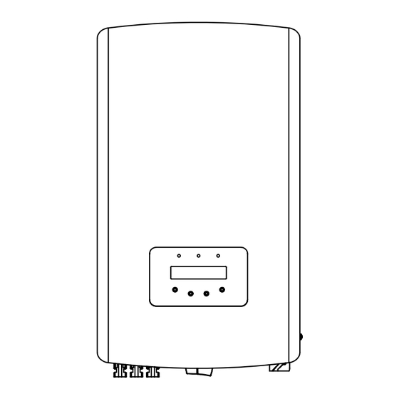
3. Overview 4. Installation 3.1 Front Panel Display 4.1 Select a Location for the Inverter To select a location for the inverter, the following criteria should be considered: WARNING: Risk of fire Despite careful construction, electrical devices can cause fires. Do not install the inverter in areas containing highly flammable materials or gases. -
Page 7: Mounting The Inverter
4. Installation 4. Installation 4.2 Mounting the Inverter Dimensions of wall bracket: Install vertically with a maximum incline of +/- 5°.If the mounted inverter is tilted to an angle greater than the maximum noted, heat dissipation can be inhibited, and may result in less than expected output power. -
Page 8: Electrical Connections
Before connecting inverter, please make sure the PV array open circuit voltage is within the limit of the inverter. Maximum 600Voc for S6-GR1P7K2, S6-GR1P7.7K2, S6-GR1P8K2 Before connection, please make sure the polarity of the output voltage of PV array matches the“DC+”and“DC-”symbols. - Page 9 4. Installation 4. Installation Please complete the assembling of the DC cable according to below procedures: Step 4: Connect the conductor part of the DC cable to the metal DC terminal and press it with the DC terminal crimping tool. Step 1: Choose a proper DC cable and strip about 7+/-0.5mm, refer to the following table for specifications.
- Page 10 4. Installation 4. Installation 4.3.2 Connect grid side of inverter Step 6: Use a multimeter to measure the DC input voltage and verify the polarity of the For all AC connections, the cables with 4-10mm diameter are required to be used. DC input cable.
- Page 11 4. Installation 4. Installation 2. Put the copper wire of the cable splitter into the plug terminal and tighten the screw. 4. Connect the AC grid connector to the inverter, until hearing a slight click sound that indicates the connection succeed. Figure 4.15 Figure 4.19 Connect the AC Connector to the Inverter 3.
- Page 12 Direct Insert Type Meter - Max input current 60A (Model:DDSD1352-C) External CT Type Meter - 120A/40mA CT is supplied (Model: ACR10RD16TE) Customer can place the order for a suitable meter from Solis Sales Reps. Below are the connection diagrams of different meters connecting to different locations.
- Page 13 4. Installation 4. Installation Pre-made Cable in Meter Package 1 2 3 4 13 12 RJ45 Connector 6 7 8 Pre-made Cable in Meter Package 5 6 7 8 9 10 21 22 23 Load L L' N N' White Black 2-Pin Connector Load...
- Page 14 Please follow below steps to assemble RJ45 connector. CT Model can only connect a smart sensor. 1. Insert the network cable into the communication connection terminal of RJ45. Please consult Solis Sales Rep before placing the order. NOTE: To achieve Export Power Management function, the smart sensor must be installed on the grid side.
-
Page 15: Start & Stop
6.2 Information side capacitors can take up to five (5) minutes to dissipate all stored energy. The Solis S6 Single Phase Inverter main menu provides access to operational data and information. The information is displayed by selecting "Information" from the menu and then by scrolling up or down. -
Page 16: Settings
Meter EnergyP: The active power. 10 sec 0000000.00k The address number can be assigned from “01”to “99”. The default address number of Solis S6 Single Phase Inverter is “01”. The status is meaningful only where “G100 Issue 2 amendment 2”is applicable. See 6.5.12.7. -
Page 17: Advanced Info
6. Operation 6. Operation 6.4 Advanced Info - Technicians Only 6.4.3 Version The screen shows the model version and the software version of the Inverter NOTE: To access to this area is for fully qualified and accredited technicians only. Model: 08 Enter menu “Advanced Info.”... -
Page 18: Advanced Settings
6. Operation 6. Operation 6.4.6 Yearly Energy 6.4.10 Inspection The function is for checking the energy generation for selected year. The display shows the Standard NO. and Work Mode of the inverter. Work Mode: YES=<ENT> NO=<ESC> Standard No. NULL Select: 2020 Figure 6.16 Inspection Figure 6.12 Select year for yearly energy... - Page 19 6.5.2 Grid ON/OFF Press the UP/DOWN keys to select the standard (AS4777-02,AS4777-15, VDE4105, This function is used to start up or stop the power generation of Solis Single Phase Inverter. VDE0126, UL-240V-A, UL-208V-A, UL-240V, UL-208V, MEX-CFE, G83/2 (for 1-3.6kW models), G59/3 (for 4-5kW models), C10/11, EN50438 DK, EN50438 IE, EN50438 NL and...
- Page 20 This function is used to set the new password for menu “Advanced info.” and “Advanced 6.5.8.1 AFCI Set information” . Solis inverters have the built-in AFCI function which can detect the arc fault on the DC circuit and shut down the inverter to prevent a fire disaster. ( ) Enable the AFCI function YES=<ENT>...
- Page 21 6. Operation 6. Operation 6.5.8.2 Discon Relay Set 6.5.9.1 DRM Settings The function is used to set the grid side relay state when the inverter AC output power is set DRM is used to control the AC output of the inverter according to different state standards. to 0% .
- Page 22 EPM OFF: function is disabled. Step 3: Select the Section 6.5.11.1 Mode Select as Option 3(Meter in Grid). Meter in Load: Solis Smart Meter is connected in the load branch circuit Step 4: Select the Section 6.5.3 24H Switch as "Enable".
- Page 23 3. CT is connected to the inverter CT port and the CT is placed at the grid side. (If necessary). CT Link State Step 7: Configure the Solis monitoring system (Please refer to the manual Correct of monitoring device) Scenario2: Only 24H Consumption load Monitoring function by Smart NOTE: Sensor.
- Page 24 Figure . 6 32 Set the backflow power For Solis single phase inverters, please select "1PH Meter" and then select the NOTE: corresponding meter model . Positive values indicate the amount of power is allowed to export to the grid.
- Page 25 CLS Ctl Set: OFF Figure 6.37 G100 ON/OFF 6.5.13 External EPM Set This setting should only be turned on when Solis external EPM device is used. 6.5.12.7.2 Backflow Current Two options are available:5G-EPM and Others-EPM. Set the desired backflow current value, and the inverter will control its power to make sure the grid backflow current less than this value.
-
Page 26: Maintenance
6. Operation 7. Maintenance 6.5.14 Restart HMI Solis Single Phase Inverter does not require any regular maintenance. The function is used for restart the HMI. However, cleaning the dust on heat-sink will help the inverter to dissipate the heat and increase its life time. -
Page 27: Troubleshooting
8. Trouble Shooting 8. Trouble Shooting The inverter is designed in accordance with the most important international grid-tied Alarm Message Failure description Solution standards and safety and electromagnetic compatibility requirements. Before delivering to Initialization system fault INI-FAULT the customer, the inverter has been subjected to several tests to ensure its optimal operation Comm. -
Page 28: Specifications
Transformerless <1 W(Night) Self consumption (night) 1. Serial number of Solis S6 Single Phase Inverter; Operating ambient temperature range -25℃...+60℃ 2. The distributor/dealer of Solis S6 Single Phase Inverter (if available); Relative humidity 0~100% 3. Installation date. Ingress protection IP66 4. - Page 29 9. Specifications 9. Specifications Model Model S6-GR1P7.7K2 S6-GR1P8K2 Max. DC input voltage (Volts) Max. DC input voltage (Volts) Rated DC voltage (Volts) Rated DC voltage (Volts) Startup voltage (Volts) Startup voltage (Volts) MPPT voltage range (Volts) MPPT voltage range (Volts) 90...500...
Need help?
Do you have a question about the S6 and is the answer not in the manual?
Questions and answers