SOLIS S6 Series User Manual
Hide thumbs
Also See for S6 Series:
- User manual ,
- Manual (50 pages) ,
- Installation and operation manual (29 pages)

Subscribe to Our Youtube Channel
Related Manuals for SOLIS S6 Series


Summary of Contents for SOLIS S6 Series
- Page 1 User Manual for S6 Series Grid Inverter Applicable models S6-GR1P0.8K-UM Applicable System Single phase system Version 1.1, Release Date: 12,2023...
-
Page 2: Table Of Contents
Contents 1. Introduction ……………………………………………………………………………………………………………………………… 1.1 Product Description ……………………………………………………………………………………………………………… 1.2 Packaging ……………………………………………………………………………………………………………………………… 1.3 Product Storage …………………………………………………………………………………………………………………… 2. Safety Instructions ……………………………………………………………………………………………………………… 2.1 Safety Symbols …………………………………………………………………………………………………………………… 2.2 General Safety Instructions ……………………………………………………………………………………………… 2.3 Notice For Use ……………………………………………………………………………………………………………………… 2.4 Notice for Disposal ……………………………………………………………………………………………………………… 3. Overview ……………………………………………………………………………………………………………………………………... - Page 3 Contents 6. Operation ……………………………………………………………………………………………………………………………… 6.1 Home Page …………………………………………………………………………………………………………………………… 6.2 Info Page ……………………………………………………………………………………………………………………………… 6.3 Alarm Page …………………………………………………………………………………………………………………………… 6.4 Setting Page ………………………………………………………………………………………………………………………… 7. Maintenance ……………………………………………………………………………………………………………………………… 8. Specifications …………………………………………………………………………………………………………………………...
-
Page 4: Introduction
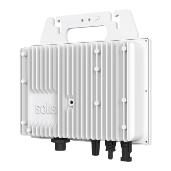
User Manual 1.1 Product Description Solis 800W Utral Mini series is for private applications for balconies, terraces, garages or outdoor installations. It converts the electricity generated by photovoltaics into alternating current that meets the requirements of the grid and feeds directly into your existing grid. -
Page 5: Packaging
1.2 Packaging When you receive the inverter, please ensure that all the parts listed below are included: Fastening screw(M6*16) x2 Inverter x1 DC connector x1 Manual C connector Manual x1 If anything is missing, please contact your local Solis distributor. -
Page 6: Product Storage
1. Introduction User Manual 1.3 Product Storage If the inverter is not to be installed immediately, storage instructions and environmental conditions are below: Use the original box to repackage the inverter, seal with adhesive tape with the desiccant inside the box. Store the inverter(s) in a clean and dry place, free of dust and dirt. -
Page 7: Safety Instructions
2. Safety & Warning User Manual 2.1 Safety Symbols Safety symbols used in this manual, which highlight potential safety risks and important safety information, are listed as follows: WARNING: WARNING symbol indicates important safety instructions, which if not correctly followed, could result in serious injury or death. NOTE: NOTE symbol indicates important safety instructions, which if not correctly followed, could result in some damage or the destruction of the inverter. - Page 8 2. Safety & Warning User Manual WARNING: No live construction is allowed, and before installation, ensure that the equipment is in good condition. WARNING: Do not touch any inner live parts until 5 minutes after disconnection from the utility grid and the PV input. CAUTION: Risk of electric shock.
-
Page 9: Notice For Use
3. The product must only be used in countries for which it is approved or released by Solis and the grid operator. 4. Use Solis products only in accordance with the information provided in the enclosed documentation and with the locally applicable laws, regulations, standards and directives. -
Page 10: Overview
3. Overview User Manual 3.1 Front Panel Display Figure 3.1 Front Panel Display 3.2 LED Status Indicator Lights Description Light Status Fault condition is detected. POWER FLASHING Alarm condition is detected. The inverter is operating properly. OPERATION The inverter is initializing. FLASHING Table 3.1 Status Indicator Lights... -
Page 11: Installation
4. Installation User Manual 4.1 System Diagram Solis balcony type mini ultra inverter integrates WIFI and Bluetooth communication modules, and is equipped with AC cables and plugs, so that the entire micro photovoltaic system can be built without additional equipment. -
Page 12: Mounting The Inverter
4. Installation User Manual 4.2 Mounting the Inverter The Ultra mini is designed to mount on the rack under PV modules. Torque : 1 N.m Figure 4.2 Inverter wall mounting 1. Evaluate the location of the Ultra mini with respect to the PV module junction box or any other obstructions. -
Page 13: External Ground Connection
4. Installation User Manual 4.3 External ground connection An external ground connection is provided at the upper side of inverter. Prepare OT terminals: M6. Use proper tooling to crimp the lug to the terminal. Connect the OT terminal with ground cable to the upper side of inverter. The torque is 2N.m. Figure 4.3 Connect the external grounding conductor 4.4 Electrical Connections Inverter designs quick-connect terminal, so top cover needn't open during electrical... -
Page 14: Connect Grid Side Of Inverter
PE wire is required to be the same as L, N wire material and cross-sectional area. Figure 4.4 AC Grid Terminal Connector Inside Each Solis S6 Single Phase Inverter is supplied with an AC grid terminal connector. Claw Body Seal body Code end terminal Figure 4.5 AC Grid Terminal Connector... - Page 15 4. Installation User Manual The steps to assemble the AC grid terminal connectors are listed as follows: 1. Disassemble the AC connector. Strip the AC wires about 7mm. Figure 4.6 Stripped AC Wires 2. Fix the wires into the correct postion. Torque 0.8N.m Please try to pull out the wire to make sure the it’s well connected.
-
Page 16: Connect Pv Side Of Inverter
4. Installation User Manual 4. Mating plug and socket: Push the locker onto the socket housing completely, then rotate the locker according to the direction instructed by the marks on the locker.(Warning:hold the body) Figure 4.9 Connect the AC Connector to the Inverter NOTE: Connection for Split phase grid. - Page 17 4. Installation User Manual WARNING: Please don’t connect PV array positive or negative pole to the ground, it could cause serious damages to the inverter. Please complete the assembling of the DC cable according to below procedures: Step 1: Choose a proper DC cable and strip about 7+/-0.5mm, refer to the following table for specifications.
- Page 18 4. Installation User Manual Step 4: Connect the conductor part of the DC cable to the metal DC terminal and press it with the DC terminal crimping tool. Positive CAUTION! Crimp Limit snaps DON'T crimp Negative Positive Crimp Negative Figure 4.13 Crimp Step 5: Insert the crimped DC cable firmly into the DC terminal, then insert the waterproof rubber ring into the DC terminal and tighten the nut.
- Page 19 4. Installation User Manual Step 6: Use a multimeter to measure the DC input voltage and verify the polarity of the DC input cable. Figure 4.15 multi-meter measurement Step 7: Connect the assembled DC terminal to the inverter as shown in the figure, and a slight "click"...
-
Page 20: Max. Over Current Protection Device (Ocpd)
4. Installation User Manual 4.5 Max. over current protection device (OCPD) To protect the inverter's AC grid connection conductors, Solis recommends installing breakers that will protect against overcurrent. The following table defines OCPD ratings for the Solis S6 Single Phase Inverters. -
Page 21: Commissioning
5. Commissioning User Manual 5.1 Preparation Ensure all the devices are accessible for operation, maintenance and service. Check and confirm that the inverter is firmly installed. Space for ventilation is sufficient for one inverter or multiple inverters. Nothing is left on the top of the inverter. Inverter and accessories are correctly connected. -
Page 22: Log In The App Via Bluetooth
5. Commissioning User Manual 5.3 Log in the APP via bluetooth Step 1: Register and log in to your account. Make Sure Your Bluetooth, WIFI, and GPRS functions are turned on. Register account, click on the upper right corner Register, select the Organization/Owner , fill in the relevant information to Register. - Page 23 5. Commissioning User Manual Step 2: local Operation. After the completion of registration, log into the brocade cloud background Go to the Overview page, and make a bluetooth connection. Click “Service” - “local Operation” - “connect With Bluetooth” < Local Operation Connect With Bluetooth Connect With WiFi...
- Page 24 5. Commissioning User Manual Step 3: WiFi Configuration (Optional) If remote monitoring function is needed, the built in WiFi can be configured to enable the data uploading on Soliscloud remote platform. Go to the Overview page and go to the following path: Click “Service”...
-
Page 25: Stop The Inverter
3. Wait approximately 30 seconds (during this time, the AC side capacitors are dissipating energy). If the inverter has DC voltage above the start-up threshold, the red POWER LED will be lit. Turn off the connection between Solis inverter and PV module. 4. Confirm all LED's switch OFF. -
Page 26: Operation
6. Operation User Manual The APP interface contains 4 sections: 1. Home 2. Info 3. Alarm 4. Settings 6.1 Home Page The home page contains the power and energy data of the inverter. The PV data and AC data are also available under this section. -
Page 27: Info Page
6. Operation User Manual 6.2 Info Page Info page displays the general information of the inverter such as inverter serial number, firmware version, grid code, etc. -
Page 28: Alarm Page
6. Operation User Manual 6.3 Alarm Page Alarm page contains the alarm code of the inverter and its corresponding troubleshooting methods. -
Page 29: Setting Page
6. Operation User Manual 6.4 Setting Page Setting page contains all the setting options of the inverter. Functions Setting Path Switch on/off the inverter Settings -> “Power ON” & ”Power OFF” Settings -> Inverter Setting-> Inverter Parameter Change inverter time setting Setting ->... -
Page 30: Maintenance
7. Maintenance User Manual Solis S6 Single Phase Inverter does not require any regular maintenance. However, cleaning the dust on heat-sink will help the inverter to dissipate the heat and increase its life time. The dust can be removed with a soft brush. -
Page 31: Specifications
8. Specifications User Manual Model S6-GR1P0.8K-UM Max. DC input voltage (Volts) Rated DC voltage (Volts) Startup voltage (Volts) MPPT voltage range (Volts) 30-500 Max. input current (Amps) Max short circuit input current (Amps) MPPT number/Max input strings number Rated output power (Watts) Max. - Page 32 Ginlong Technologies Co., Ltd. No. 57 Jintong Road, Binhai Industrial Park, Xiangshan, Ningbo, Zhejiang, 315712, P.R.China. Tel: +86 (0)574 6578 1806 Fax: +86 (0)574 6578 1606 Please adhere to the actual products in case of any discrepancies in this user manual. If you encounter any problem on the inverter, please find out the inverter S/N and contact us, we will try to respond to your question ASAP.
Need help?
Do you have a question about the S6 Series and is the answer not in the manual?
Questions and answers