Advertisement
- 1 General Information
- 2 Using the Scan Tool
- 3 Update
- 4 Feedback
- 5 Safety Precautions and Warnings
- 6 Documents / Resources
General Information
On-Board Diagnostics (OBD) II
The first generation of on-board diagnostics (ca led OBD l) was developed by the California Air Resources Board (CARB) and introduced in 1988 to monitor some components of vehicle emission control. With the advancement of technology and the desire to improve the on-board diagnostic system, a new generation of on-board diagnostic system was developed. This second generation on-board diagnostic system is called "OBD II"
The OBD II system is designed to monitor emission control systems and major engine components by performing either continuous or periodic tests of specific components and vehicle conditions. When a problem is detected, the OBD II system turns on a warning light (MIL) on the vehicle's instrument panel to alert the driver, typically with the words "Check Engine" or "Service Engine Soon." The system also stores important information about the detected malfunction so a technician can accurately find and fix the problem.
Below are three such valuable pieces of information:
- Whether the malfunction indicator lamp (MIL) is set to 'On' or 'Off;
- Whether diagnostic trouble codes (DTCs) are stored and if so, which ones;
- Status of the standby monitor.
Diagnostic Trouble Codes (DTCs)
OBD II Diagnostic Trouble Codes are codes stored by the on-board computer diagnostic system in response to a problem detected in the vehicle. These codes identify a specific problem area and are intended to give you an indication of where in the vehicle a fault may be occurring. OBD II Diagnostic Trouble Codes consist of a five-character alphanumeric code. The first character, a letter, indicates which control system sets the code. The other four characters, all numbers, provide additional information about where the DTC originated and what operating conditions triggered it. Below is an example that illustrates the structure of the digits:

Figure 1-2: Explanation of a diagnostic trouble code.
Location of the Data Link Connector (DLC)
The DLC (Data Link Connector or Diagnostic Link Connector) is the standardized 16-pin connector used to connect diagnostic tools to the vehicle's on-board computer. The DLC is typically located 12 inches from the center of the instrument panel (dashboard), under or on the driver's side of most vehicles. If the Data Link Connector is not located under the dashboard, there should be a sticker there indicating its ocation. On some Asian and European vehicles, the DLC is located behind the ashtray and the ashtray must be removed to access the connector. If you can not find the DLC, check the vehicle's service manual to see where it is located.

Figure 1-3: The DLC connector (left) is located in the area of the vehicle interior you see on the right (black arrow).
Using the Scan Tool
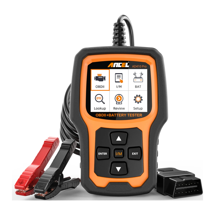
Tool Description - ANCEL AD410 Pro

- LCD DISPLAY - Displays test results. 2.4" TFT 262K true color, 320*240 QVGA LCD display.
- ENTER BUTTON - Confirms a selection (or action) from a menu.
- EXIT BUTTON - Cancels a selection (or action) from a menu or returns to the menu.
- UP SCROLL BUTTON - Scroll up an item by item menu
- DOWN SCROLL BUTTON - Scroll down an item-by-item menu
- "IIM" BUTTON - Quick State Emissions Readiness Check and Drive Cycle Check.

Comments:
MIL Yellow- Dashboard
MIL ON MIL Grey Dashboard MIL OFF
 -no support
 -complete
 -not complete
- OBDII CONNECTOR
Connect the scan tool to the vehicle's Data Link Connector (DLC)
Specifications
- Display: 2.4" TFT 262K true color
- Operating temperature: O to 600C (32 to 140 OF)
- Storage temperature: -20 to 700C (-4 to 158 OF)
- Extemal power supply: 8.0 to 18.0 V power supply from vehicle battery
Supplied accessories
- ANCEL AD410 Pro OBD2 diagnostic tool
- 16PIN connection cable and clamps
- USB Cable - Connect to a computer for online upgrade
- User Manual - Instructions for operating the tool
BAT FUNCTION
Preparations before the test When performing the test in the vehicle, make sure all auxiliary loads are turned off, the key is not in the ignition, and the doors are closed
Connecting the tester
- Connect the red clamp to the positive (+) terminal and the black clamp to the negative (-) terminal
- To make a proper connection, move the clamps back and forth. The tester requires that both sides of each clamp be firmly connected before testing. If the connection is poor, a CHECK CONNECTION WIGGLE CLAMPS message will appear, clean the clamps and reconnect the clamps.
- The preferred test position is at the battery terminals. If the battery is not accessible, you can also perform the test at the jumper terminal; however, the measured available power may be ower than the actual value.
Battery Test
From the main menu, use the navigation keys UP/DOWN to select the menu BAT and press the key ENTER. The screen will display the interface shown below:

Battery Type: ScrolI to and select Regular Flooded, AGM Flat Plate or AGM Spiral, if applicable.
Battery Standard: Scrol to and select the battery's rating system. Not all rating systems are available for every application
| Standard | Description | Range |
| CCA | Cold Cranking Amps, as specified by SAE The most common rating for cranking batteries at O oF (-17.8 oC) | 100-2000 |
| DIN | Deutsche Industrie-Norm | 100-1200 |
| JIS | Japanese Industrial Standard, shown on a battery as a combination of numbers and letters. | 26A17 thru 245H52 |
| EN | Europa-Norm | 100-2000 |
| IEC | International Electrotechnical Commission | 100-1200 |
| GB | China National Standard | 30-220Ah |
| SAE | Society of Automotive Engineers Standard | 100-2000 |
| MCA | Marine Cranking Amps standard, effective starting current value at O oC | 100-2000 |
| BCI | Battery Council International standard | 100-2000 |
| CA | Cranking Amps standard, effective starting current value at OoC | 100-2000 |

Battery Test Results
| Decision | Interpretation |
| GOOD BATTERY | Return tbe battery to service Fully charge the battery and |
| GOOD-RECHARGE | Fully charge the battery and return it to service |
| CHARGE&RETEST | Fully charge the battery and retest. FaiIure to fully charge the battery before retesting may cause inaccurate result. If CHARGE&RETEST appears again after you fully charge the battery, replace the battery. |
| REPLACE BATTERY | Replace the battery and retest. A REPLACE BATTERY result may also mean a poor connection between the battery cables and the battery. After disconnecting the battery cables, retest the battery using the out-of-vehicle test before replacing it. |
| BAD CELL-REPLACE | Replace the battery and retest. |
 Note: In the battery test, select the appropriate data according to the actual situation of the battery to finally determine the health of the battery.
When you select the battery current size, press the UP button once to set the 5A current up, and press the down button once to set the 5A current down. You can adjust the current according to the actual situation of the battery.
Cranking test
With this function you can read the battery voltage in real time

If you press[ENTER]and start detection, the interface will be displayed:

Charging test
Press charging test and it will display:


Review Data
When you press Check data, the data of the last battery test is displayed as follows:

DTC Lookup
The DTC Lookup function allows you to search for definitions of codes stored in the built-in code library
- From the main menu, use the UP /DOWN keys to select Code Lookup and press ENTER


To query the error code, press enter + up, cursor to the left; press enter + down, the cursor to the right.
For manufacturer specific codes, you must select a vehicle make in an additional screen to search for DTC definitions If no definition is found (SAE or manufacturer specific), the scan too will display "DTC definition not found!". Please refer to the vehicle's service manual"
- Press the EXIT key and return to the main menu.
Review
This function allows you to review the recorded DTCs. Select the [Review] menu and press the ENTER key. The screen will be displayed as follows:

Setting up the tool
The scan tool allows you to make the following adjustments settings:
- Select language: Select the language you want to use
- Unit of measurement: Set the unit of measurement to English or Metric
- Set Beep: Switches ON [OFF beep tone.
- Record: ON Turns recording on/off. Turn on the recording function to record the error code information (operation on vehicle)

Reviewing and printing diagnostic reports(operation on a computer)
*Download the upgrade file from the ANCEL website.
*the device is connected to the computer via a USB cable.
*open the "Update" application
![]()
*Click " Review & Print " and automatically generate diagnostic DTC


- Background
- Feedback
- Tool information.
![]()

I/M
Select [11M]and the following is displayed

OBD II Diagnostics
- Turn on the ignition
- Locate the vehicle's 16-pin Data Link Connector (DLC)
- Plug the scan tool cable connector into the vehicle's DLC
- Press ENTER to enter the main menu. UP Use the IDOWN key to select Diagnostics from the menu


- Press ENTER to confirm
If the message "LINKING ERROR!" appears on the display.
- Make sure that the OBD II connector of the scan tool is firmly connected to the DLC of the vehicle;
- Turn off the ignition and wait for about 10 seconds. Turn the ignition back on and repeat the test.
Read Codes
- Select [Read Codes] and press ENTER in the diagnostic menu. If there are some codes, the screen will display the codes as follows.


- According to the above figure, select another item by pressing UP or DOWN and press ENTER to confirm.


- After viewing all codes, you can press EXIT to return to the previous menu.
Erase Codes
- Select [Erase Codes], the screen will display the interface shown below. Press ENTER to delete the DTCs, the screen will display the interface shown below:


- Press ENTER according to the figure above. The screen will display the interface shown on the next page:


Notes: Before performing this function, be sure to retrieve and record the error codes
After clearing, retrieve the error codes again or turn on the ignition and retrieve the codes again. If there are still error codes in the system, please troubleshoot the codes using factory diagnostic guide, clear the codes and check them again
I/M Readiness
Select I/M readiness and press ENTER. The screen displays the interface shown below:

I/M readiness is to test misfire/fuel system/comprehensive component, you can use UP or DOWN to select and press ENTER as follows:

N/A means not available for this vehicle, INC means incomplete or not ready, 0K means completed or monitor is ready.
Data stream
Press the UP or DOWN key to select Data Stream from the main menu, then press ENTER to confirm. The screen will display the interface shown below:

Select [View All Items ] and press the ENTER key. The screen displays the interface shown below:

Scroll the page, press up to the last page or down to the next page Select [ Select item ] and press Enter.
Then press the Enter key again, which will be displayed as follows:

Scroll page, press enter + up, to previous page, press enter + down, the next page.
After you select something and press exit, the screen will be displayed as follows:

Select [View Graphic Items] from the Data Stream menu and press ENTER. The screen displays the interface shown below:

Scroll, press enter + up, to previous page, press enter + down, to next page. Press enter again to select.
Press EXIT to return to the display:

Maximum number of lines is 3.
Press EXIT to return to the previous menu
Display Freeze
Frame When an emission-related error occurs, a snapshot of the current vehicle parameters is recorded by ECU Note: If the DTCs have been deleted, the freeze data may not be stored in the vehicle From the main menu, select Freeze Frame. The screen will display the interface shown below:

You can use the UP / DOWN key to view the data. Press EXIT to return to the Diagnostics menu.
O2 sensor test
OBD II regulations established by SAE require that applicable vehicles monitor and test oxygen (O2) sensors to detect problems related to fuel efficiency and vehicle emissions. These tests are not demand tests and are performed automatically when engine operating conditions are within specified limits. These test results are stored in the on-board computer memory.
The O2 Sensor Test function allows you to retrieve and display the O2 Sensor Monitor test results for the most recently performed tests from the vehicle's on-board computer.
The O2 sensor test function is not supported by vehicles that communicate via a Controller Area Network (CAN). The results of the O2 sensor test of vehicles with CAN can be found in the "On-Board Mon. Test" chapter.
Select O2 Sensor Test from the Diagnostic Menu and press ENTER The screen will be displayed as shown below:

Press ENTER, the screen will be displayed as shown below (data is different each time):

Test or Component (Evap System Test)
The OBD2 system monitors the fuel system for fuel vapor leakage to ensure that no hydrocarbons (HC) leak into the atmosphere. EVAP monitor does two things:
- Ensure that the gasoline vapor is sent to the intake pipe at the right time, and mixed with the air to enter the engine for combustion
- Prevent fuel vapor in the fuel pipe from leaking into the atmosphere and polluting the environment. [Evap System Test] function: The external diagnostic device can't control the fuel evaporation control (EVAP) of the OBD system, and the diagnostic device only displays its status and test resu ts If the car supports this function, it will display as below:
 = Step 1")
 = Step 1")
If the car not supported the function, it will display as below:
 = Step 2")
Vehicle Information
Select [Vehicle Information] and press ENTER. The screen displays information such as (Vehicle Identification number), (Calibration Identifications), and( Calibration Verification), as shown below (different data will be displayed for different vehicles):

Press EXIT to return to the diagnostics menu.
Update
- Download the update software and unzip the file
- Connect the device to the computer using a USB cable
- The update software is only supported by 7/8/10. In Windows 7, you need to install the driver, in Windows 8/10, you can run the update software directly.
Note: Windows XP and Apple computers do not support upgrades. If you do not understand the upgrade steps in the instructions, please contact ANCEL customer service
Feedback
- If the [OBDII] function indicates an error associated with the vehicle, please use the feedback function Select [Feedback] and the following will be displayed:


Select [Start recording] to open the recording function and the following will be displayed:

Next: Press EXIT and return to the main menu. Select the [OBDII] menu to restart the detection and record the data
Transfer the data to your computer and generate the feedback file Download the upgrade file from the ANCEL website to your computer. The device is connected to the computer via a USB cable Select the "Update" file and the following is displayed:

Click on "Feedback" and the following will be displayed:

Please send the feedback.bin file to support@ance tech com

Safety Precautions and Warnings
To avoid injury or damage to the vehicle and/or scan tool, first read this manual and observe the following safety precautions when working on a vehicle:
- Always perform vehicle tests in a safe environment.
- Do not attempt to operate or observe the unit while driving a vehicle Operating or observing the device distracts to the driver and may result in a fatal accident.
- Wear safety glasses that meet the standards of ANSI.
- Keep clothing, hair, hands, tools, test equipment, etc. away from all moving or hot engine parts.
- Operate the vehicle in a well-ventilated area: Exhaust fumes are toxic.
- Place blocks in front of the drive wheels and never leave the vehicle unattended while performing tests
- Use extreme caution when working near the ignition coil, distributor cap, ignition wires and spark plugs. These components generate dangerous voltages when the engine is running.
- Keep a fire extinguisher nearby that is suitable for gasoline, chemical, and electrical fires
- Keep the scan tool dry, clean, and free of oil/water or grease. If necessary, use a mild detergent on a clean cloth to clean the outside of the scan tool
Documents / ResourcesDownload manual
Here you can download full pdf version of manual, it may contain additional safety instructions, warranty information, FCC rules, etc.
Advertisement


Need help?
Do you have a question about the AD410 Pro and is the answer not in the manual?
Questions and answers